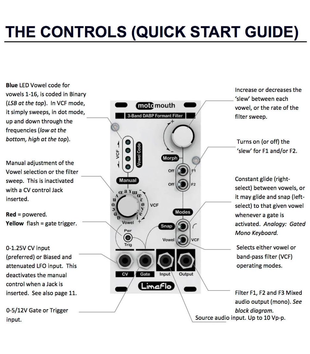
Thank you for choosing the Motomouth DIY kit. This is an intermediate to advanced build. We recommend that you follow these instructions and the most recent BOM while building. The parts in the instructions might have some minor changes, so please reference the the BOM at all times. Let’s begin!
Resistors and D5 Diode
Populate the flat-laying resistors on the logic board. These include R17, R20, R29 (all 4.7k) and R30 (150k). Resistors are non-polarized, so it doesn’t matter which direction you put them on the PCB, but it will help with any troubleshooting that may arise if you line up all the tolerance bands on one side. This will make it easier to read the color codes on the resistors. Bend one leg of the resistor over, then place the it on the board.
Populate the D5 diode. Diodes are polarized, so make sure to populate them with the cathode stripe in the same direction as indicated by the silkscreen.
Once everything is in place, carefully flip your project over and solder the components in place. Clip any excess leads on the bottom of the board.
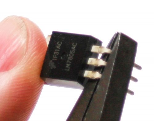
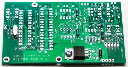
Main Board Voltage Regulator & Crystal
First take the voltage regulator and bend the leads at a 90 degree angle as shown above
Next, place the voltage regulator in the PCB and secure it down the PCB with a 3mm screw and a 3mm square nut.
You can now place the crystal in the main board as shown below. The crystal is not polarized, so you can place it in either way. Carefully turn the board over to solder and then clip excess leads.
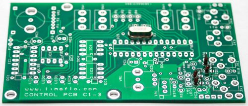
Standup Diodes and Control Board Crystal
Now place the standup diodes in both PCBs as shown below. D3, D4, D5, D6 and D7 are on the logic board; the rest are on the control board. The black band on the diode should be oriented toward the circle on the silkscreen. Carefully turn over to solder and clip excess leads.
You can now place the crystal in the control board as shown below. The crystal is not polarized, so you can place it in either way. Carefully turn the board over to solder and then clip excess leads
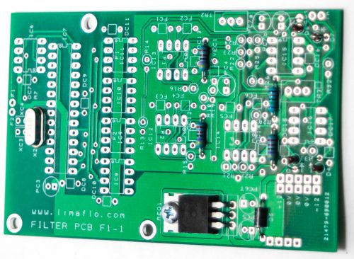
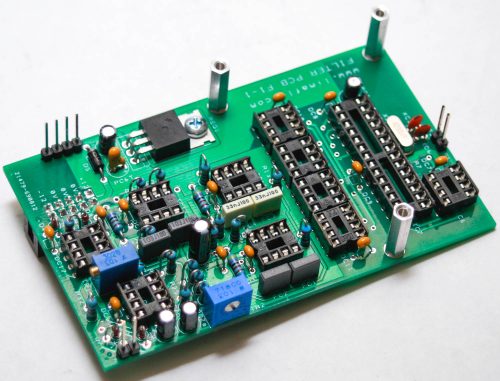
IC Sockets
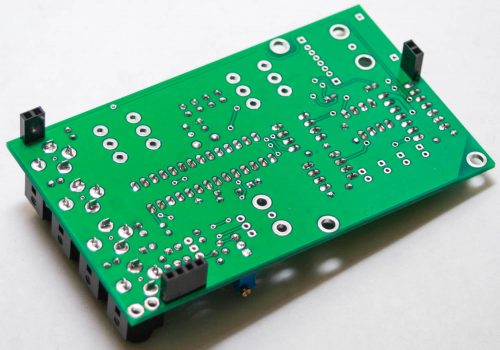
Next up are the IC sockets. Take care when populating these to not bend any of the legs. Line up the notch at the end of the socket with the notch on the silkscreen. This notch indicates where pin 1 of the IC is. When you have them populated, carefully flip your project over and solder everything in place.
A trick to getting these nice and flat is to only solder one or two pins of each socket, and then reflow the solder joint while gently pushing on the top of the socket to seat it flat against the PCB. Then continue on and solder the rest of the pins.
Ceramic Capacitors
Now we can populate the ceramic capacitors. These are non-polarized and can be inserted either direction. If the capacitor coating runs down the legs a little, make sure the coating doesn’t poke into the pads. Once they are in, carefully flip over your project and solder them in place, clipping the excess leads.
Film, Tantalum & Electrolytic Capacitors
First, populate the film capacitors into the main board. These are non-polarized and can be inserted either direction.
Next insert the tantalum capacitor. It is polarized, so match up the small ‘+’ sign on the cap with the ‘+’ on the board.
The electrolytic capacitors are polarized, so take care! Ensure that the longer leg (the leg that is further from the stripe indicator on the body) goes through the solder pad with the little ‘+’ symbol next to it. If the silkscreen doesn’t have a ‘+’ on it, line up the stripe on the cap with the line on the silkscreen.
Once they are aligned properly, carefully flip your project over and solder it in place, clipping the excess leads on the bottom.
Standup Resistors
Now populate the standup resistors as shown below. Carefully turn the project over, solder and clip excess leads.
Trimmer Potentiometers
Populate the three trimmer pots as shown below. Align the trimmer shaft/screw with the shaft/screw outline on PCB silk screen. Align the trimmer screw of TR2 to the edge of the PCB. Carefully turn the PCB over to solder then trim excess leads.
10 Pin Power Header
Populate the keyed 10 pin power header as shown below. There is no marking indicating the polarity on this side of the board. We highly recommend that you use the KEYED HEADER!
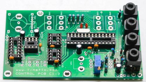
Jacks
Populate the four jacks into the control PCB as shown below. Very carefully turn the board over and solder in place.
Spacers
Take the three metal spacers (female/female) and connect them via three metallic 2.5mm screws and connect them to the main board as shown below
Headers and Sockets
Start by populating the main board long-pin headers as shown below. Again be careful to solder these in straight. One trick to do this easier is to put a small amount of solder on just one pin then hand-bend the header in perfect place. You can now solder the rest of the pins.
Do the same for the control board sockets as shown on the 2nd photo below.
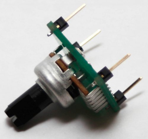
VR2 Sub Board Assembly
Take the dual Pot and place it into the PCB as shown below. Make sure you position the pot on the side of the board with the silk screen facing up (this is important!).
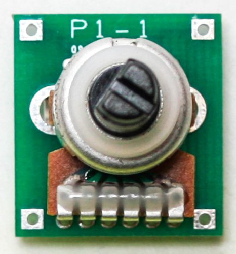
Bend over the two placement tabs and solder those and the six pins as shown below
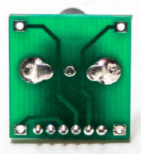
Take the four header pins and solder them in place as shown below.
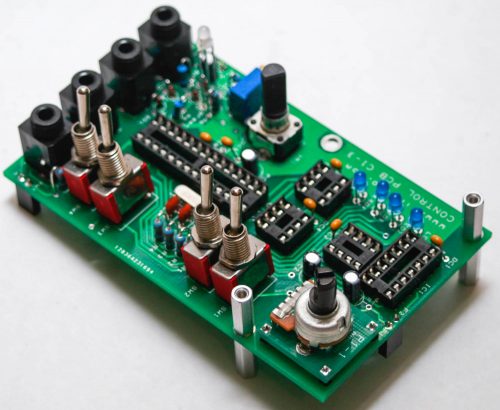
LEDs, Pots, 2nd Row Headers & Switches
First screw the 2nd row of spacers (male/female) to the 1st row as shown below. You will need to unscrew the 1st row of spacers (female/female) from the main board and connect them to the the bottom side of the control board. This helps in proper panel assembly.
Then populate all the LEDs. The blue LEDs are polarized and need to have the long lead (anode) of the LED inserted into the pad with the “+” silk screen. The Red/Green LED needs to be oriented differently. The Red/Green LEDs that we supply in the kits are have a longer red lead. Insert the longer lead into the hole marked ‘red’ on the silk screen. DO NOT SOLDER ANYTHING YET!
Now place the switches in the PCB as shown below. Make sure one of the nuts is on the shaft prior to placing the panel on the project (these are used to help support the panel). OPTIONAL: You can omit the switch nuts altogether, as they are not essential to keeping the product secure. DO NOT SOLDER ANYTHING YET!
Now place VR1 into the PCB and VR2 with the assembled sub-board. DO NOT SOLDER ANYTHING YET!
Panel Placement
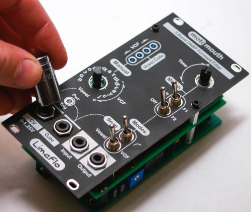
Take the panel and carefully place it on the project as shown below
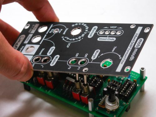
Add the two black 2.5mm hex screws on to the spacers and add a couple nuts onto a couple jacks. This will hold the components in place.
At this point you can push the LEDs through the panel as far as you like. You can add a piece of tape over the LED panel holes if you want to have partially recessed LEDs.
You can now carefully turn the project over to solder the LEDs, pots, and switches.
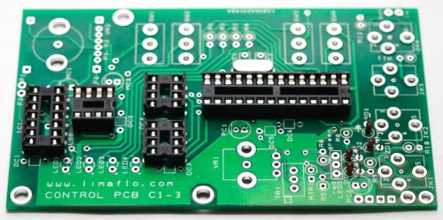
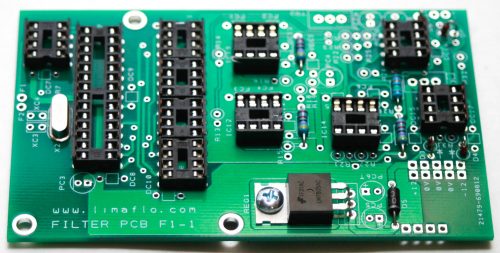
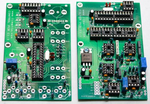
Integrated Circuits
Remove the panel and place the standoffs on the main board with the 2.5mm screws as shown below. Now insert the ICs into their sockets. You will need to bend the legs inward a little to make them fit. Make sure that all the legs are firmly seated in the socket and that the notches on the ICs match the notches on the sockets! If there is no notch on the IC then match the side that has the dot over pin one of the IC in the side of the socket that has the notch.
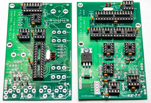
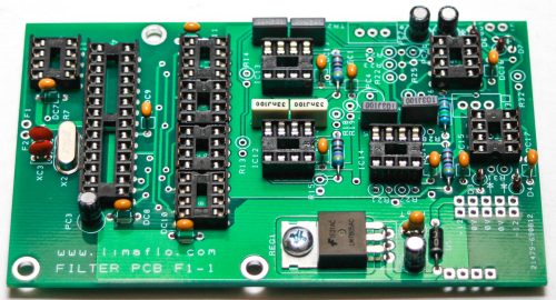
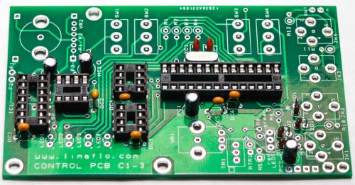
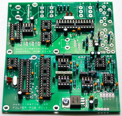
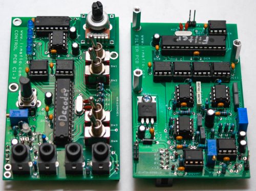
Note: The ATMEGA ICs are marked “D” and “F.” The Decoder IC goes on the control board and the Filter IC goes on the logic board. See the pictures below.
Final Board Assembly
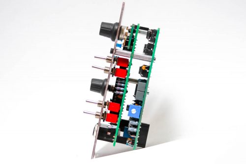
CAREFULLY! (as to not bend any pins) connect the Control Board to the Main Board together.
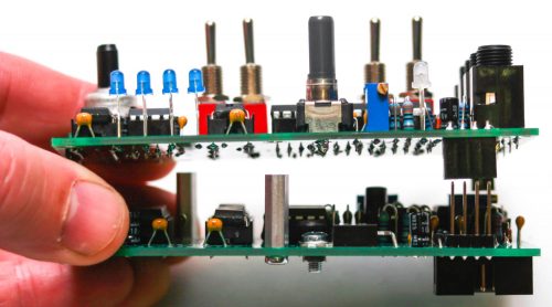
Screw in the remaining 2.5mm metallic screw and add the 2nd row of standoffs again as shown below.
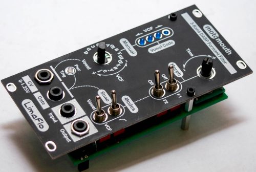
Now place the panel back on to the project and screw down the screws and nuts (not too hard!). The nuts for the jacks are optional. Push the knobs onto the potentiometers.
You are a superstar if you made it this far! Time for final checks and onward to calibration and testing!
Calibration
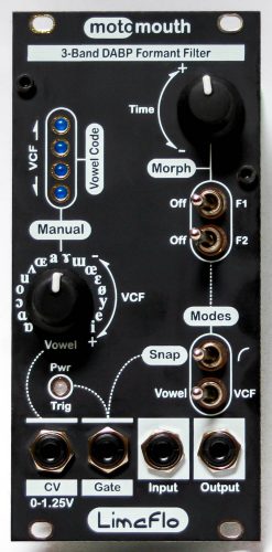
INPUT GAIN – TR2
The audio input is calibrated to receive a 10V peak to peak audio signal. This is the ‘factory set’ value, and doesn’t usually need to be adjusted. If your input to Motomouth is higher and/or there is notable distortion (clipping), and you can’t attenuate the incoming signal in any way, the trimmer can be turned counter-clockwise gradually until the distortion disappears.
Should you need to use audio ‘Line’ levels (~4.5 V p-p or less, typically +/- 1.7V), and you require higher output levels, then the trimmer can be turned fully clockwise (but remember the initial trimmer position so that you can return to it later if you need).
OUTPUT BIAS SIGNAL – TR3
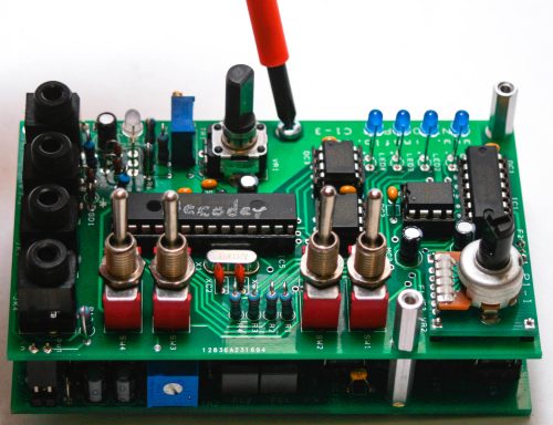
Unplug cables connected to the CV, Gate and Input. Using a multimeter or an oscilloscope, trim the output 0VDC.
CV INPUT – TR1
First turn the VCF pot FULLY Clockwise with nothing connected. On the control board next to the CV jack are two unpopulated holes, labeled JK1. Using a multimeter or oscilloscope, connect the ground to the hole closest to the corner of the board and the tip to the hole beside it. Measure across those two holes, adjusting TR1 until it reaches 1.25V. When this is done, each vowel should operate on a 1V/Oct basis (it’s quantized). You will know you’ve done it correctly if, when the module is in Vowel mode, the VCF pot shows no LEDs when fully counterclockwise, but all four LEDs when fully clockwise.