


Thank you for purchasing the Synthrotek Five Amp Eurorack power supply kit! The original non paneled version of this product was our first power supply ever! We have come a long way since then, but this certainly one of the most beefy supplies for the money! This is an intermediate build. It is very important to get all the components properly soldered into the PCB in the correct placement. If you feel like you can handle it, please proceed! If not, get some help from a friend with experience or purchase a fully completed unit.
Please build according to the BOM, and not these instructions or the pictures alone. Some components may have changed since these were written, or we may not be able to get the exact looking components in the pictures.
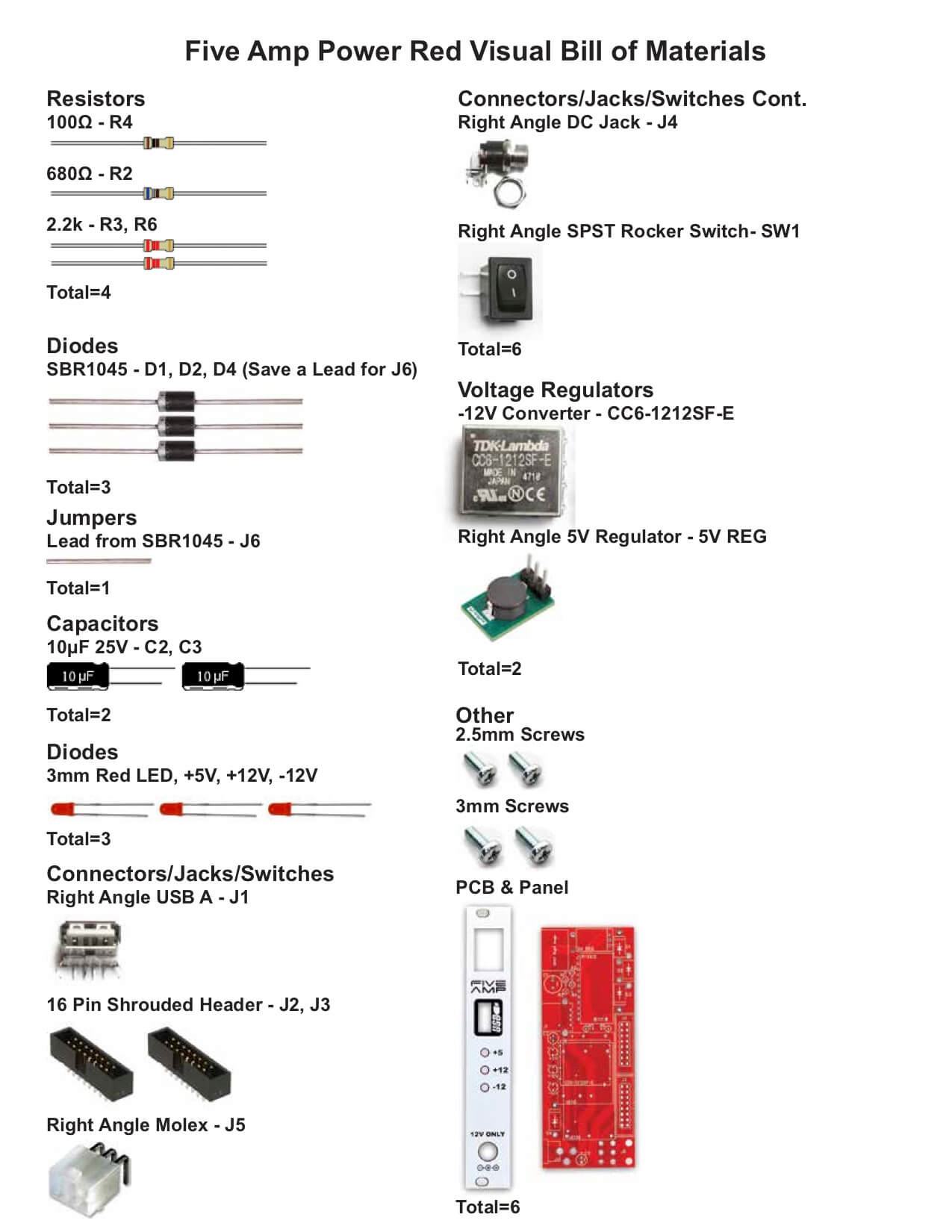 For the Five Amp Red BOM with Mouser part numbers, click here.
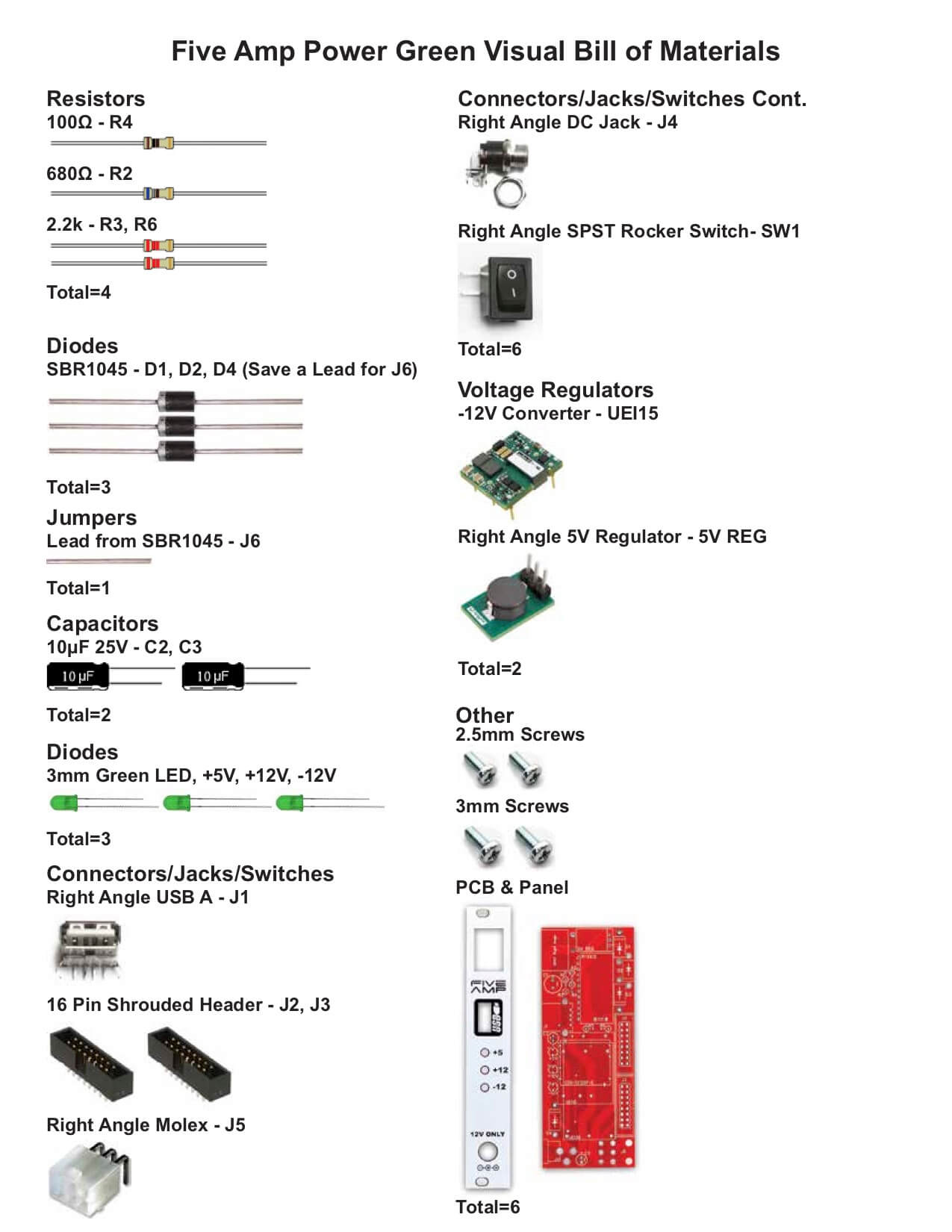
For the Five Amp Green BOM with Mouser part numbers, click here.
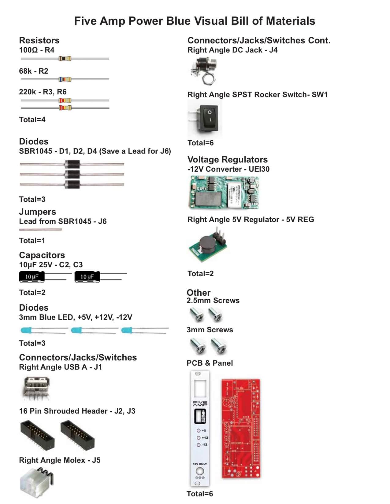
For the Five Amp Blue BOM with Mouser part numbers, click here.
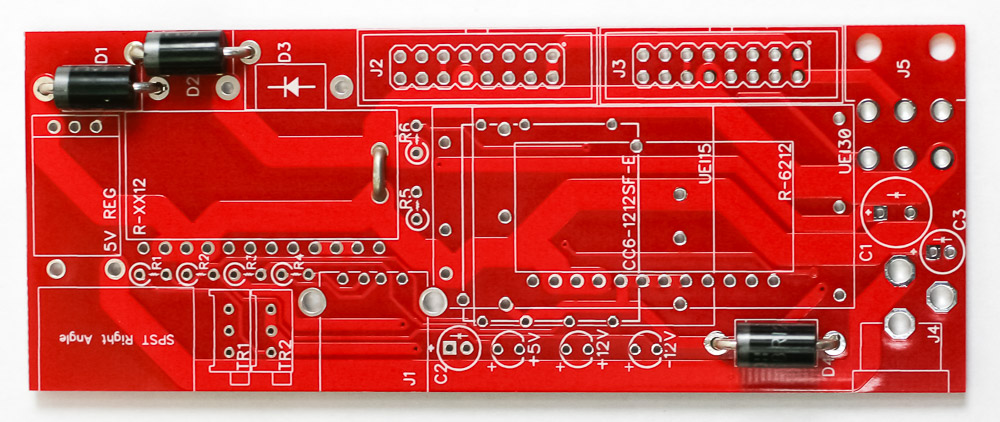
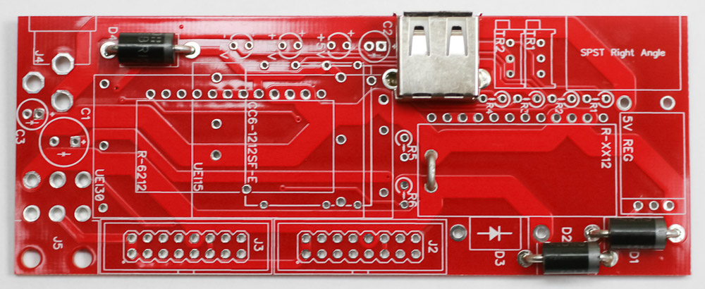
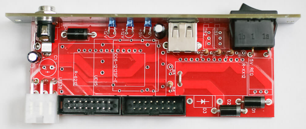
Main Board Diodes & Jumper
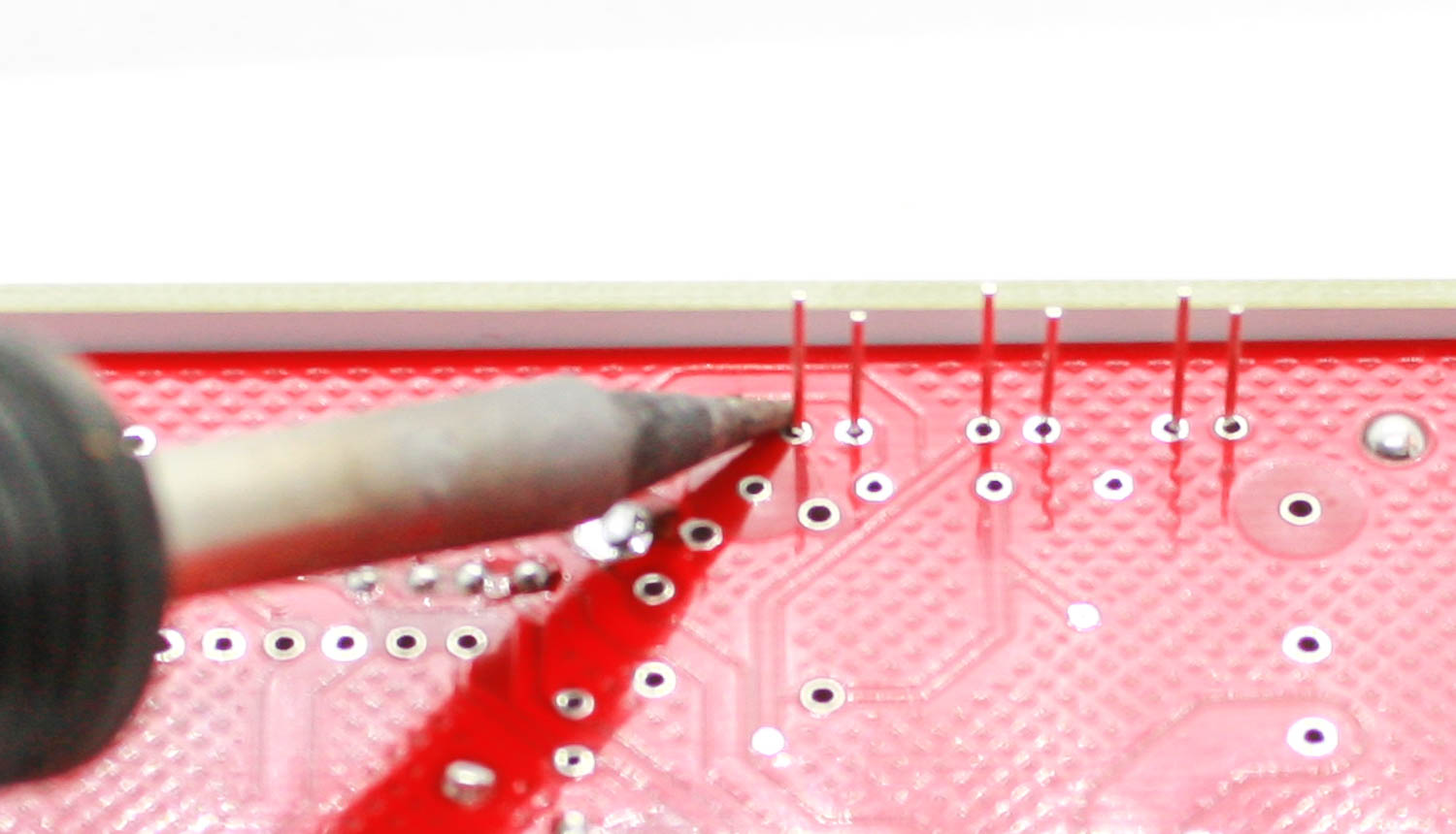
The Five Amp power supply uses the same PCB as Super Power II but does not use all of the footprints on the PCB. Place your diodes in the PCB as shown below and keep a longish diode lead clipping to use as a jumper. The diodes are polarized, so make sure to populate them with the cathode stripe in the same direction as indicated by the silkscreen. Take that lead clipping and place in the PCB as shown for part R-XX12.
Once everything is in place, carefully flip your project over and solder the components in place. Clip any excess leads on the bottom of the board.
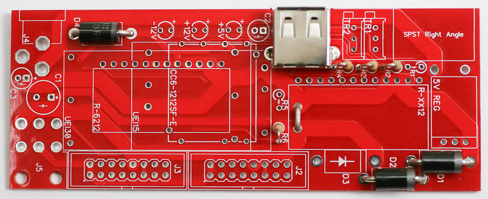
Main Board USB Jack
Place the USB jack into the PCB as shown below.
Once everything is in place, carefully flip your project over and solder the components in place. Clip any excess leads on the bottom of the board.
Main Board Stand Up Resistors
Populate the resistors. Resistors are non-polarized, so it doesn’t matter which direction you put them in the PCB. It is easier to pre-bend the resistors before placing them into the board.
Once everything is in place, carefully flip your project over and solder the components in place. Clip any excess leads on the bottom of the board.
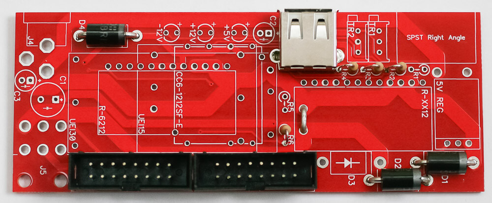
16 Pin Power Connectors
Next up are the keyed shrouded power headers. Make sure when populating this that the notch in the header is lined up with the notch designed on the silkscreen. Carefully turn over to solder.
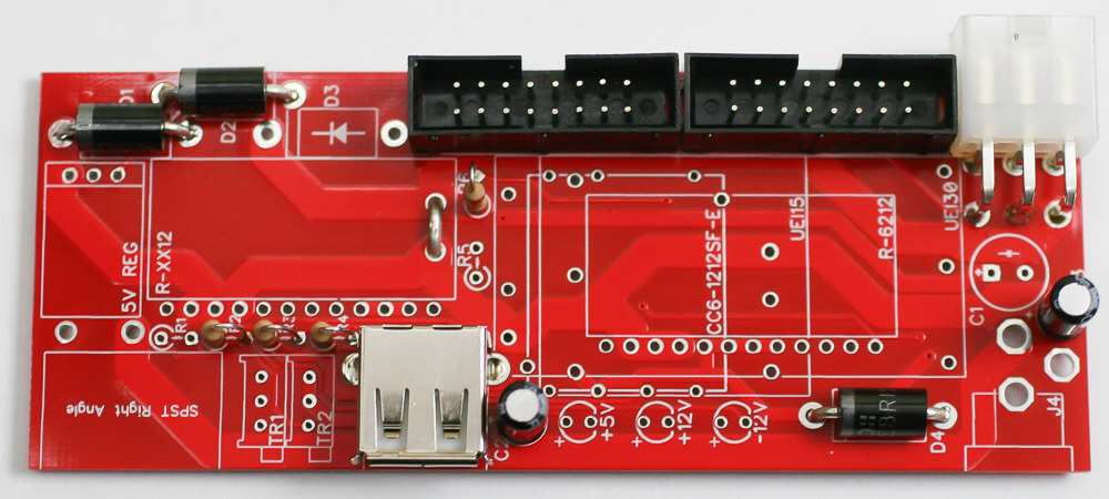
Molex Power Connector & Caps
Synthrotek has a fast, safe and easy way to connect your power to multiple power distribution boards through our Molex power connector. Place this connector in the PCB as shown below, turn over and solder in place.
The electrolytic capacitors are polarized, so take care! Ensure that the longer leg (the leg that is further from the stripe indicator on the body) goes through the solder pad with the little ‘+’ symbol next to it.
Once it is aligned properly, carefully flip your project over and solder it in place, clipping the excess leads on the bottom.
Power Switch
The power switch will take a little extra pressure to snap in place, so please be careful while doing this. Please place it in as shown below ONLY!
Five Amp Power Panel Switch 1
LED Bending
Pre-bending the LEDs will make the job much easier. Bend them just as shown below prior to placing them into the PCB.
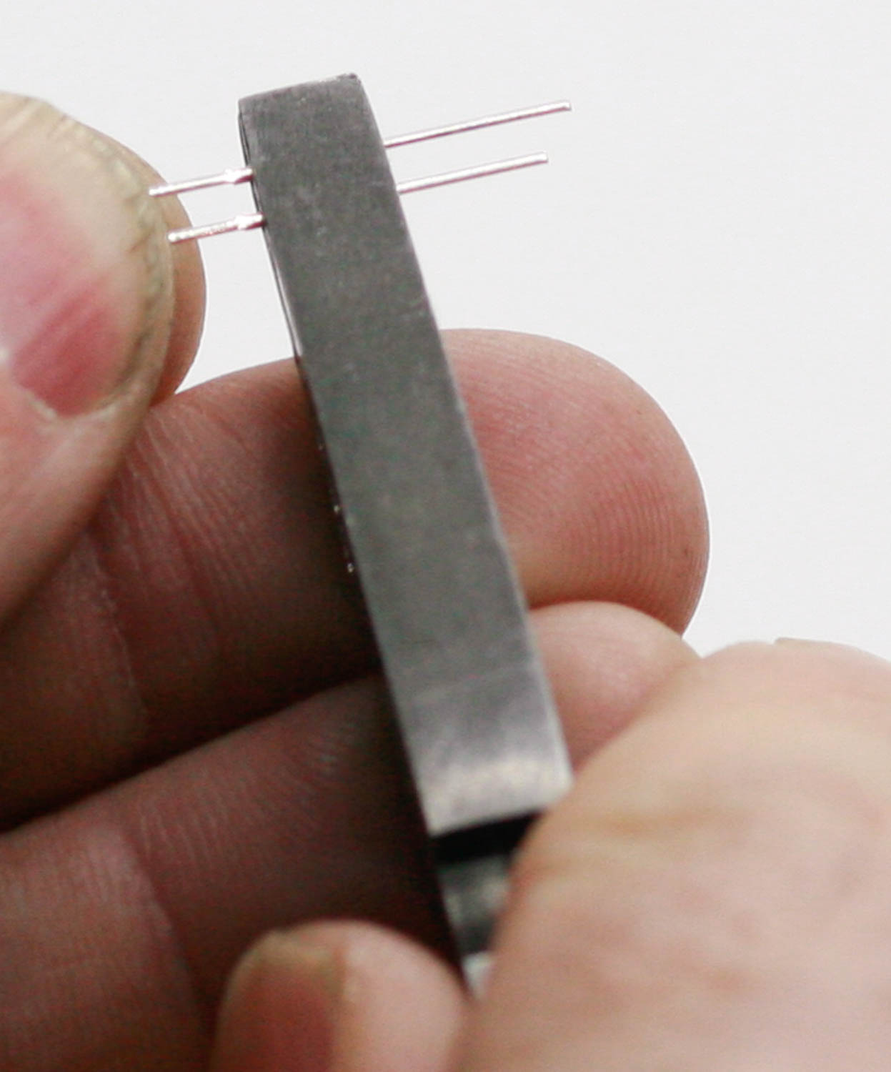
power supply LED bending 1
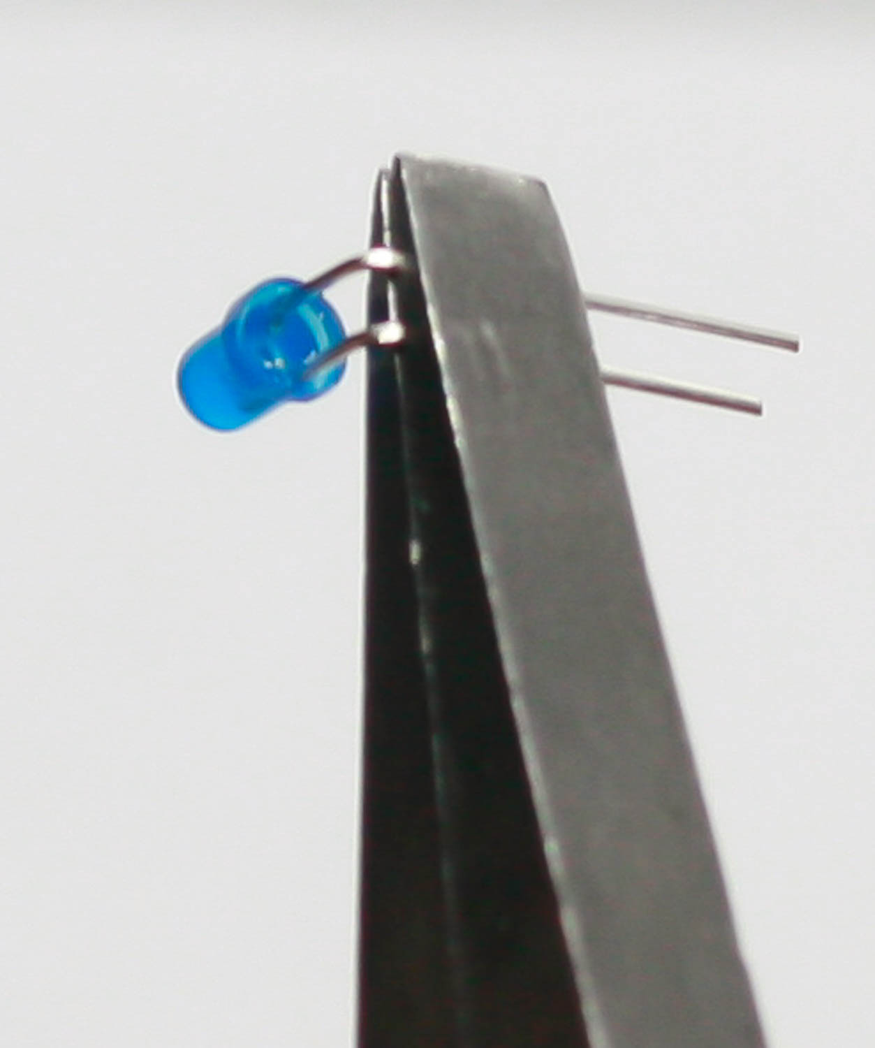
power supply LED bending 2
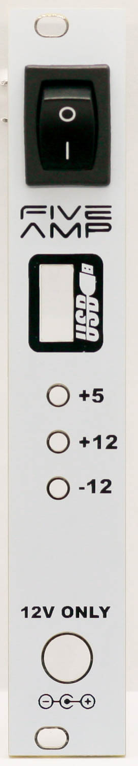
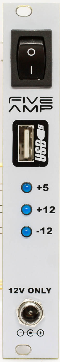
Panel, LEDs and Power Jack
Marry the DC power jack, on/off switch and LEDs with the panel and PCB. DO NOT SOLDER ANYTHING JUST YET. This can be a tad tricky, so please take your time. You can now hand-tighten the DC jack nut to secure the panel to the jack.
Once you have everything square and lined up, carefully turn the project over and solder the items in place. Clip excess leads.
Soldering LEDs
Alignment of PCB and Panel
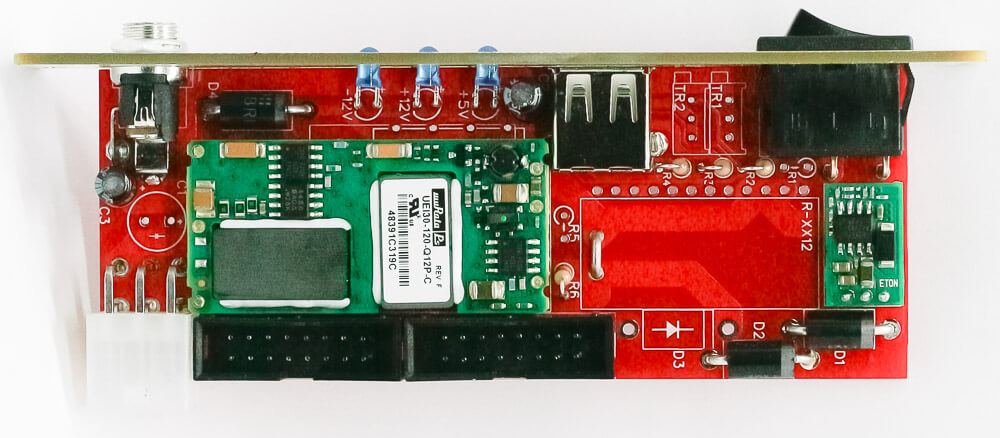
-12V & +5V DC to DC Converters
Synthrotek only uses the best DC to DC converters available on the market. Take the -12V converter (converter will vary based upon which amount of power you purchased) and place it in the board as shown below and do the same for the +5V converter. The -12V converter’s lead will only fit into the PCB (regardless of style) ONE WAY. Do not force or bend anything. Once in place, carefully turn over to solder. It can help to let the panel and switch hang off the table to keep the converters flat. Trim excess leads.
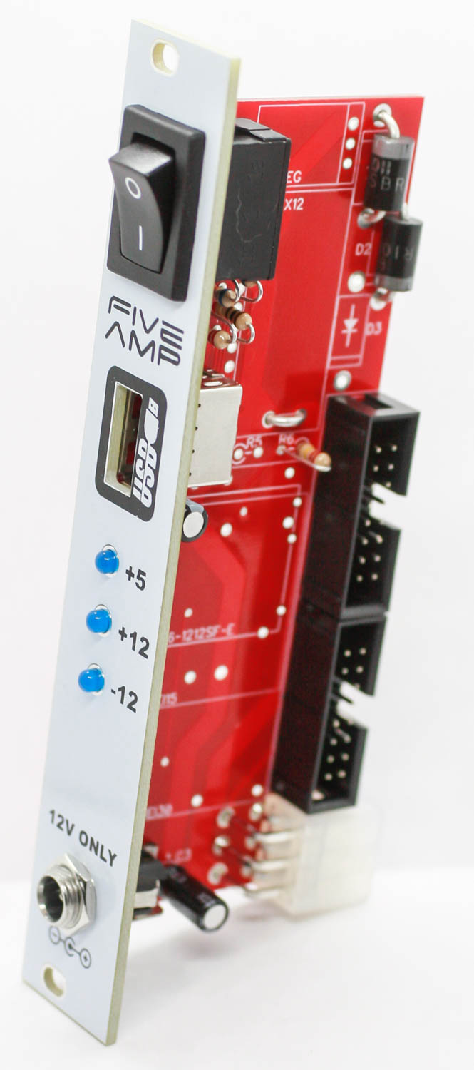
Completed Unit
Congratulations on your build! It is now time to power the unit on with the a 12V center positive adapter ONLY. If you are unsure for any reason about your power brick adapter, DO NOT PLUG IT IN and buy what you need from Synthrotek directly. This module passes +12V directly from your brick to the modules. Carelessness can damage your modules and will void any warranties.
Five Amp Power Completed