


Important Links
Product Page
Store Page
Assembly Instructions
Bill of Materials
Capacitor and Resistor Lookup Guide
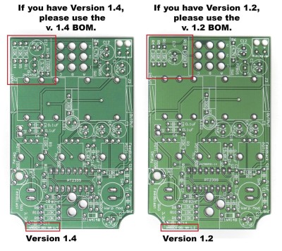
Version 1.4 has the buffer mod built into the board; for version 1.2, the buffer mod is optional. There is no other difference between the boards.
Please note!!
We have made a couple of helpful changes to the build order of this pedal. We are working to update the instructions, but in the meantime, please watch the video below to see how it all fits together BEFORE you start the project. The machine pin headers are no longer soldered directly into the PCB at the beginning, they are soldered to the pots first.
Cosmic Echo (v. 1.4) Assembly Instructions
Thank you for purchasing our Cosmic Echo effect pedal kit. Please follow these instructions in order, as it can be tricky to build and insert into the enclosure.
PLEASE ALSO FOLLOW THE BOM AND NOT JUST THE PCB OR THESE INSTRUCTION PICTURES, THE BOM HAS THE BEST UPDATED COMPONENT VALUES.
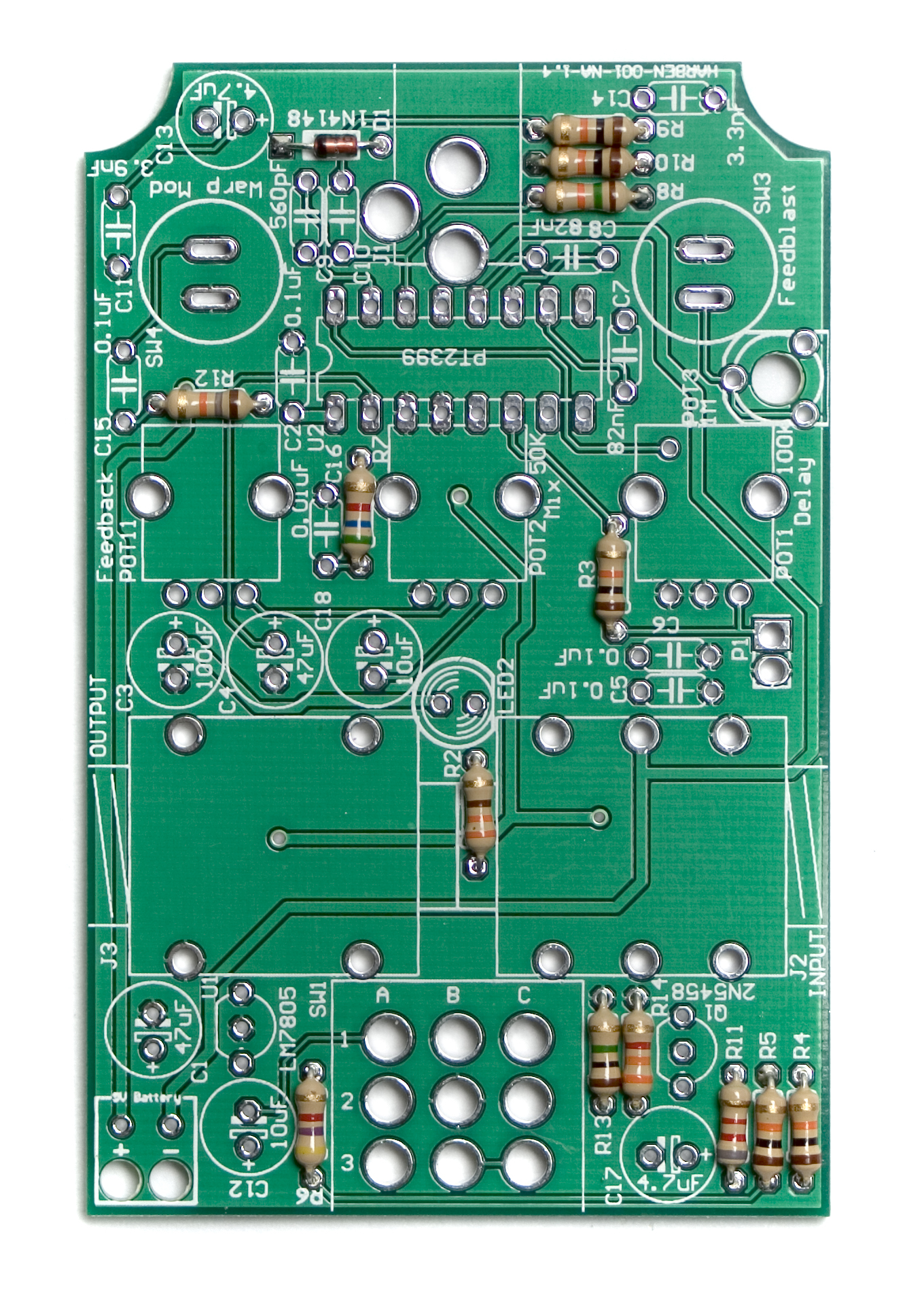
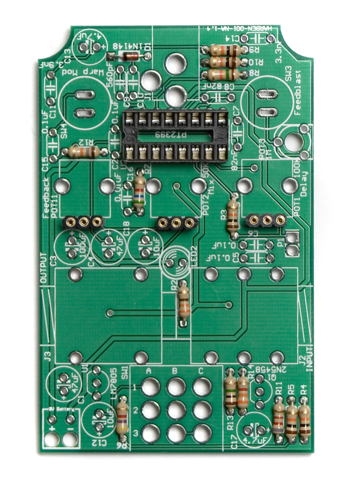
Buffered Cosmic Echo Resistors and Diode
It is really helpful to build your kit from the shortest components to the tallest. That means that every time you need to flip the PCB over to solder and clip leads, you can rest the PCB on a flat surface and your board will be flat as well (much easier for soldering). So lets start with populating the resistors and diodes. Remember that diodes are polarized components. You must orient the diodes by matching the stripe on the diode to the white stripe on the PCB.
3 PIN SOCKETS
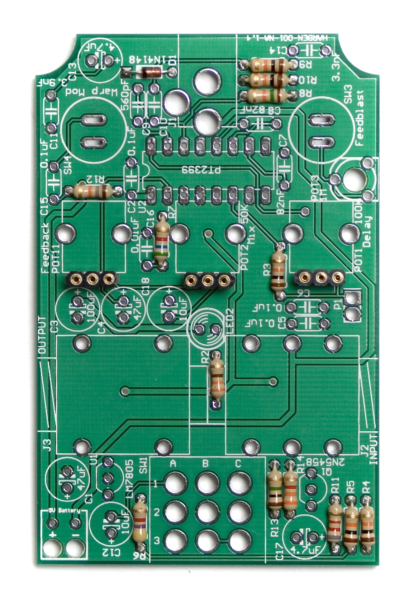
Cosmic Echo 3 Pin Sockets
Some kits include a taller pot and do not need these sockets. Now place the 3-pin metal headers in as shown above and carefully flip the PCB over and solder them into place. Notice that there is a plastic black sleeve that holds the header pins together. DO NOT overheat these while soldering as they will melt and be harder to use. If you are having trouble keeping them in the board when you flip it over, you can use a little piece of tape to hole them in place while soldering.
IC SOCKET
Cosmic Echo IC Socket
Next place the IC Socket into place and solder on the back side of the PCB. Make sure you align the notch on the socket with the same notch in the silkscreen of the PCB.
CERAMIC CAPACITORS
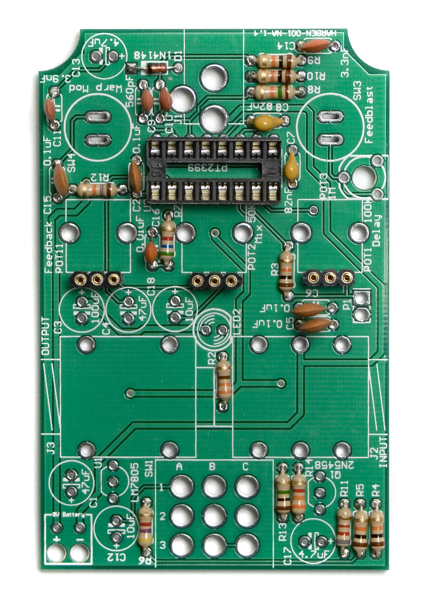
Cosmic Echo Ceramic Caps
Now populate the ceramic capacitors, then turn over and solder then clip the leads. Your capacitors may look a little different, so make sure you read the codes and follow the visual bom prior to soldering components. Populate, solder and trim.
ELECTROLYTIC CAPACITORS
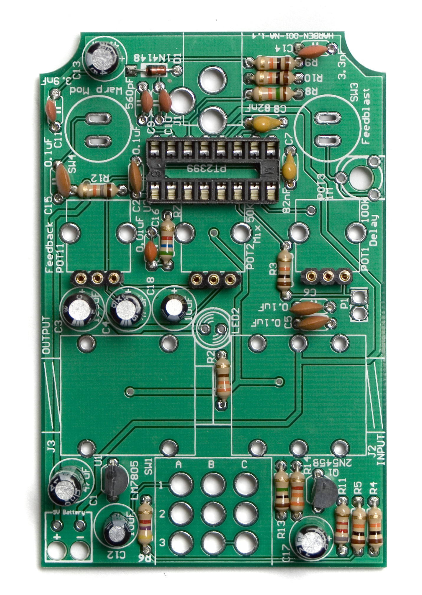
Cosmic Echo Electrolytic Capacitors
Next, populate the electrolytic capacitors by lining up the longer lead (anode) with the ‘+’ marking on the PCB. Solder, then trim. Carefully align the notch on the IC with the notch on the socket and PCB silk screen.
DC JACK AND TRIMMER POTENTIOMETER
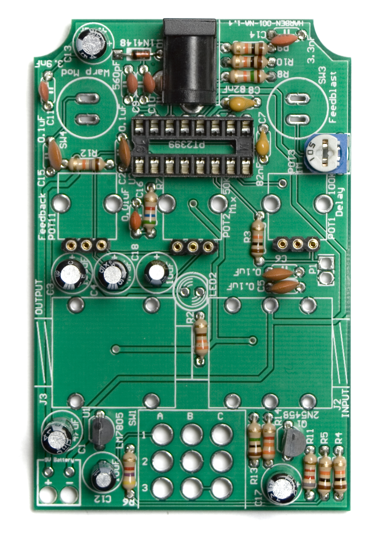
Cosmic Echo DC Jack and Trimmer Potentiometer
First, populate the DC jack, turn over and solder. Then add the trimmer potentiometer (used to dial in the desired amount of ‘feedblast’ when the momentary switch is engaged), solder and clip.
AUDIO JACKS
Cosmic Echo Audio Jacks
Next up are the Input (stereo) and Output (mono) jacks. Insert them into the PCB as shown above, then flip over and solder them into place.
3PDT STOMP SWITCH
Cosmic Echo Stomp Switch
Now insert the 3PDT stomp switch into place, with the flat side facing the front and back of the boards, as shown above. Then flip over your project and solder into place.
9v BATTERY CLIP
Cosmic Echo 9v Battery Clip
Next up, insert the ends of the battery clip through the strain relief holes in the PCB, and then solder each wire into its proper spot. The red goes to the one marked with a ‘+’ and the black wire goes to the ‘-‘.
TRIMMING POTENTIOMETERS
Please note: Some kits include a taller pot and do not need to be trimmed.
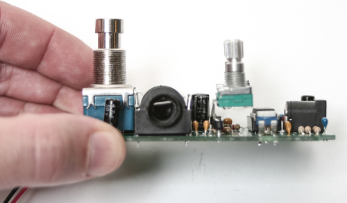
The 9MM potentiometers need to be trimmed in a few places to properly fit into this project. All 4 PCB mount clips should be cut to the base of the body of the potentiometer. Please see photos below:
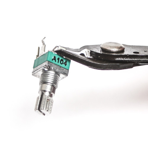
Clipping Potentiometers
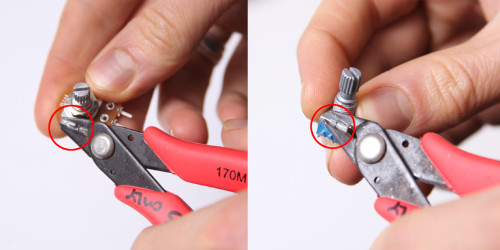
Don’t forget to cut the nubs on the potentiometers as necessary.
PLACING & SOLDER POTS
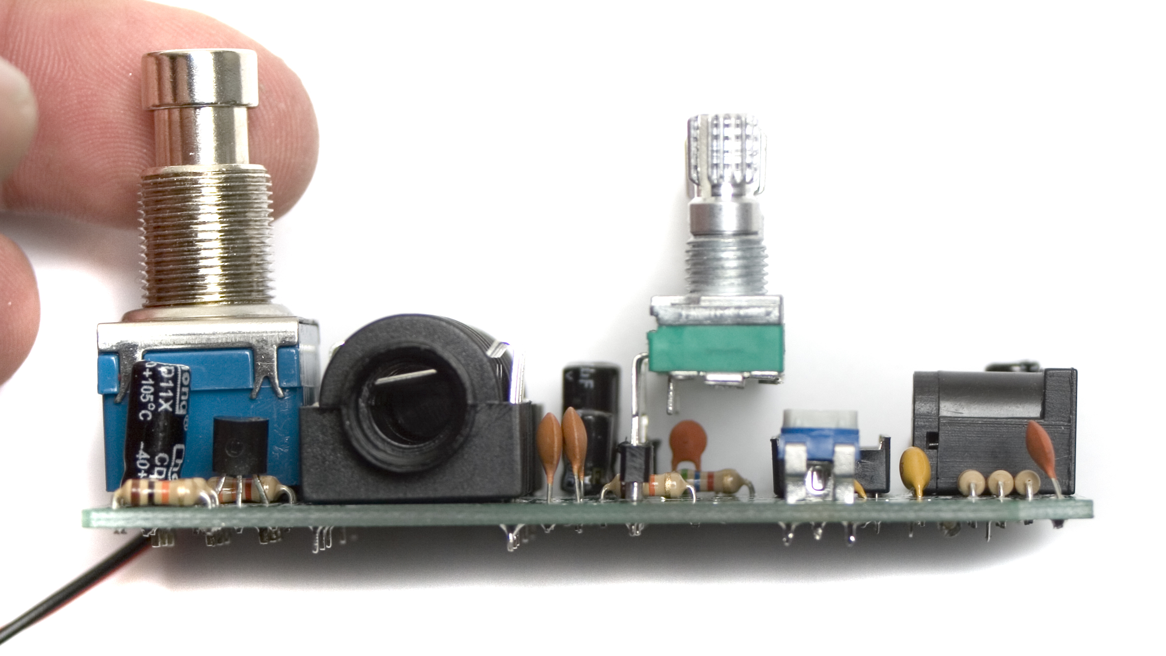
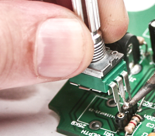
Cosmic Echo Pot Alignment
Now we want to place the trimmed pots (as shown above) onto the 3-pin headers. Before you try to solder the pots to the 3-pin heads it is advisable to add a small amount of solder to one of the pins of each header first. This will allow you to align the pots on place and hold down one pin before soldering the rest. This is the best method to avoid melting the 3-pin header. After this, solder the remaining pins as shown below.
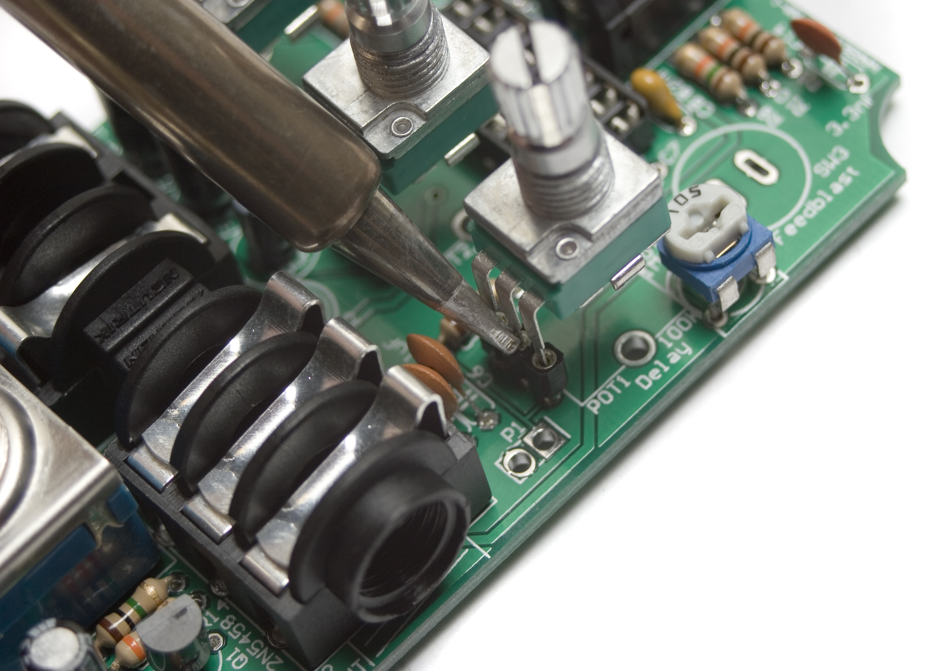
Cosmic Echo Pot Soldering
Now would be a good time to go ahead and insert the PT2399 Chip into its socket. Make sure you align the notch in the chip with both the notch in the socket and the one on the PCB as well.
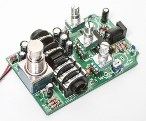
Once you have successfully soldered the pots on, the project should look as it does below.
EXTENDING PUSH BUTTON SWITCH LEADS
The momentary push button switches on the Cosmic Echo are JUST long enough to be soldered into the PCB with the enclosure in place. If you are having any difficulty with this, please follow these optional instructions to extend the solder leads for an easier fit into the enclosure.
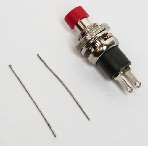
Momentary Switch Lead Extension
You will need a couple of spare trimmed resistor leads (4 total).
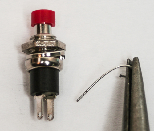
Momentary Hooks
Next, use some needle-nosed pliers and make a small hook on each lead.
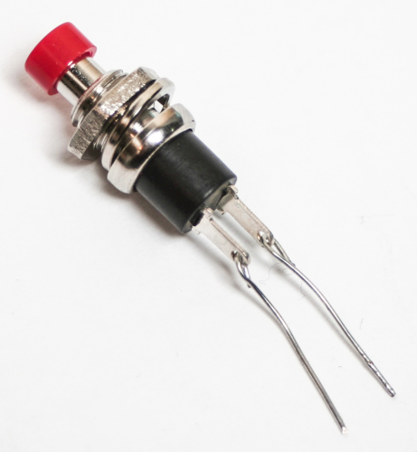
Solder Leads to Switches
Now hook each lead to the solder lugs on the momentary switches, then solder in place. Make sure your hook eyelets are not too big as to now fit into the PCB.
ENCLOSURE INSTALLATION
LED for case assembly
Populate the LED into the PCB by lining up the FLAT side of the LED with the Flat indicator on the silk Screen (DO NOT SOLDER YET!). LEDs are polarized components and will only work if inserted the correct way. Allow the LED to remain unsoldered until you put the project into the enclosure.
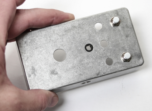
Cosmic Echo Enclosure Switches
Now push the black plastic LED Bezel into the enclosure as shown above and take your two momentary switches and remove all of the nuts and washers. Then insert the switches into the switch holes and barely screw one of the nuts (per switch) onto the switch threads so that the switches are held down. Again, just barely. We will need as much of the switch as we can get if you did not follow the switch extension instructions. If you followed those instructions, you can use more of the switch threads.
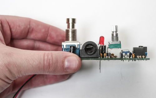
Cosmic Echo Enclosure Placement
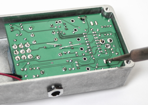
First make sure you have removed ALL of the washers and nuts from your 3PDT Stomp Switch. Now carefully (do not rush this or force anything) slide the project into the enclosure and push the LED through the bezel and bend the leads to mark your placement. Also make sure that your switch leads (if you followed those instructions) poke through the vias as shown below.
Switch Leads
Before you solder anything, tighten the Audio Jack Nuts on each side. This will help align the project into the case.
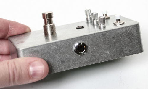
Add Audio Jack Nuts
Now solder the switch leads and LED leads and trim excess.
Cosmic Echo Switch Lead Soldering
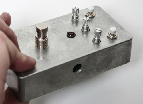
Now add and tighten down the Pot and 3PDT Stomp Switch nuts (not too hard). Then you can gently tighten the momentary switches as well.
Tighten Nuts
CONGRATS!
You have assembled your Cosmic ECHO and are ready to shred. If you have any issues after putting the project in a case, carefully remove it and look for a connection that could have broken and repair. If everything is working fine, you can screw the enclosure backplate on and start to rawk! If you have any issues, please consult our TROUBLESHOOTING GUIDE.
BE SURE TO USE ONLY A 9V CENTER NEGATIVE POWER BRICK OR A 9V Battery.
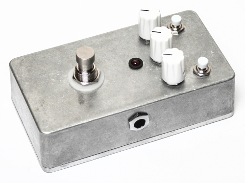
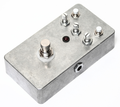
Finished Cosmic Echo
Cosmic Echo (v. 1.2) Assembly Instructions
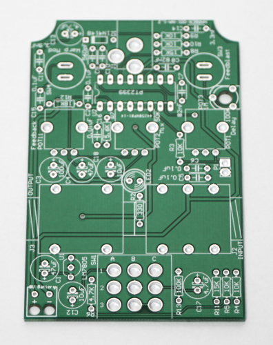
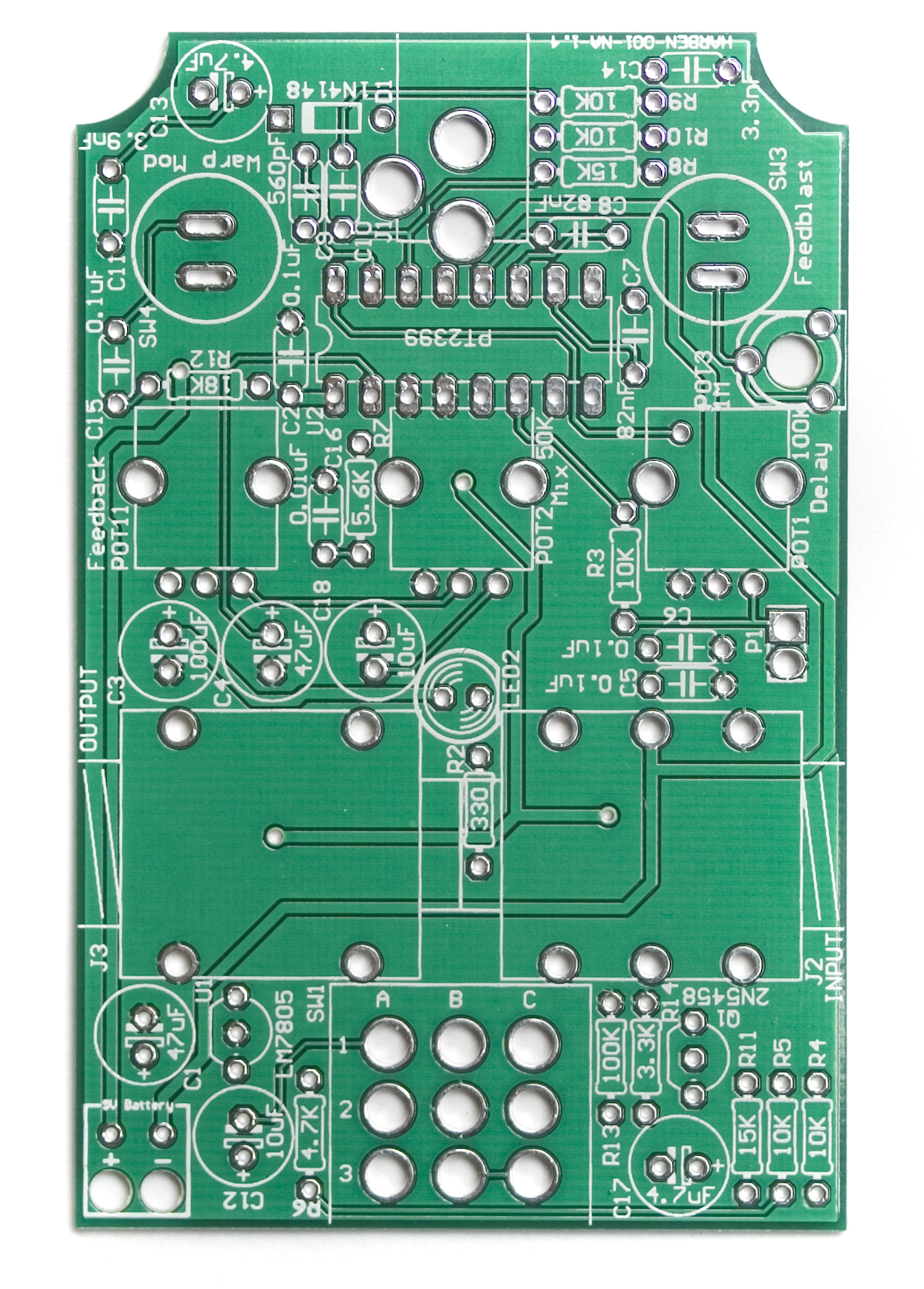
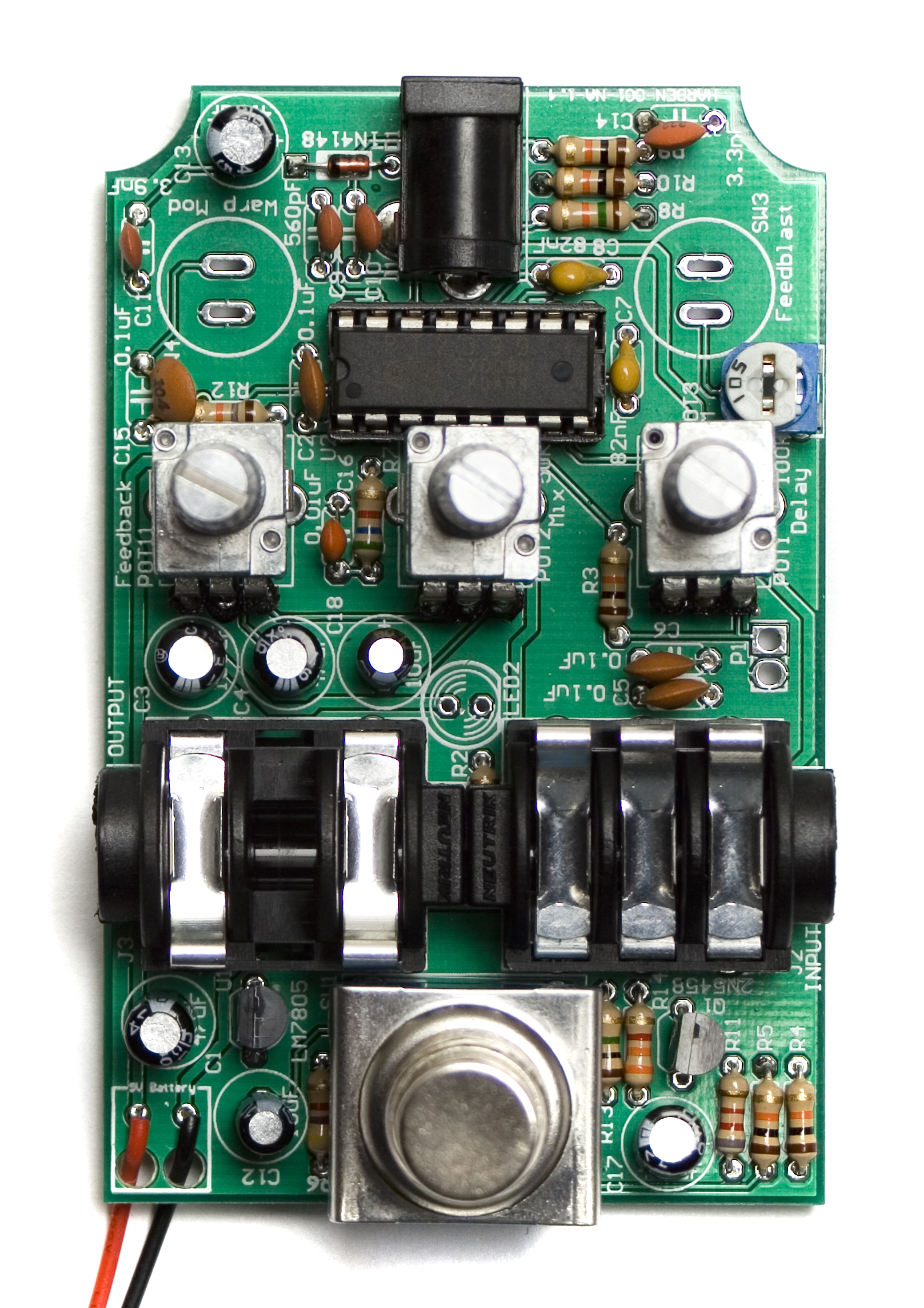
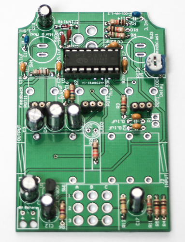
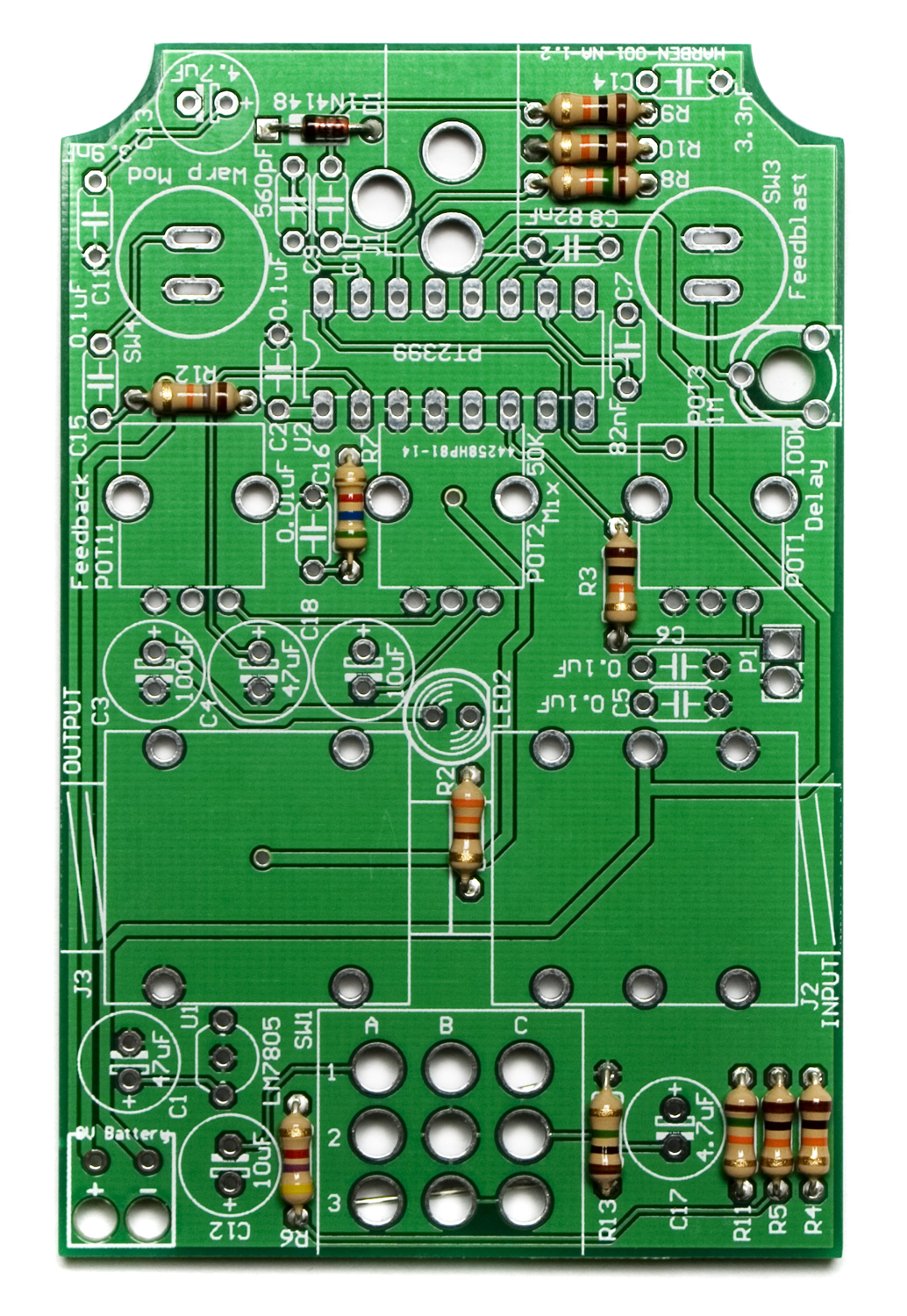
Cosmic Echo PCB
Thank you for purchasing our Cosmic Echo effect pedal kit. Please follow these instructions in order, as it can be tricky to build and insert into the enclosure.
PLEASE ALSO FOLLOW THE BOM AND NOT JUST THE PCB OR THESE INSTRUCTION PICTURES, THE BOM HAS THE BEST UPDATED COMPONENT VALUES.
Optional Output Buffer Mod
We have designed an optional mod for the Cosmic Echo, which is highly recommended. It is a JFET buffer for the output that reduces the volume drop of the circuit significantly. If you would like to do this mod, please scroll to the bottom of the page, and follow those instructions first.
RESISTORS & DIODES
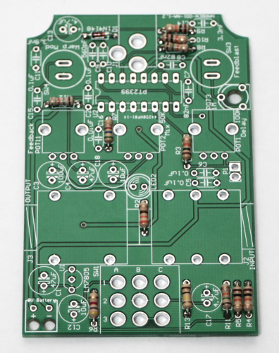
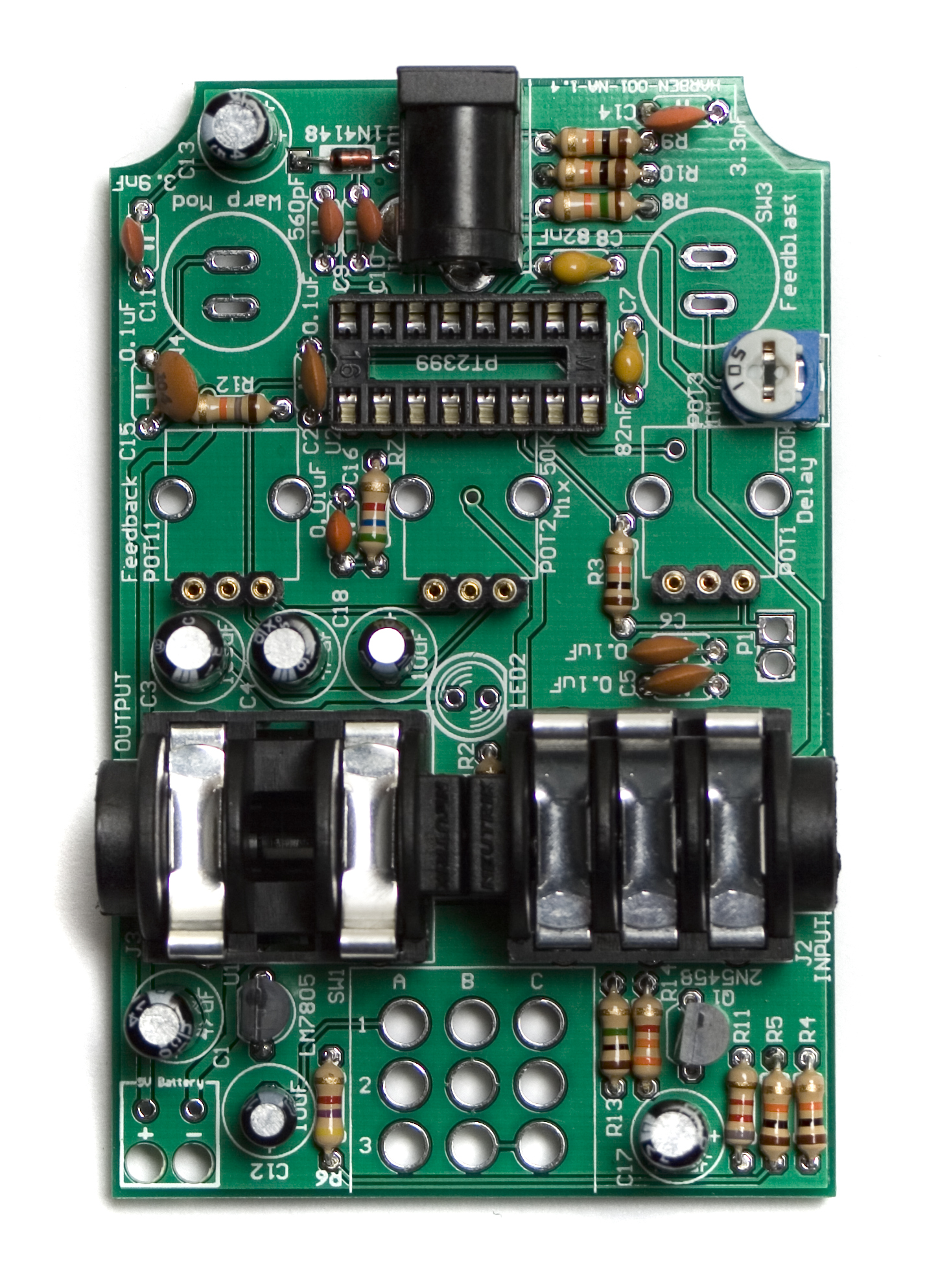
Cosmic Echo Resistors & Diodes
It is really helpful to build your kit from the shortest components to the tallest. That means that every time you need to flip the PCB over to solder and clip leads, you can rest the PCB on a flat surface and your board will be flat as well (much easier for soldering). So lets start with populating the resistors and diodes. Remember that diodes are polarized components. You must orient the diodes by matching the stripe on the diode to the white stripe on the PCB.
CERAMIC CAPACITORS
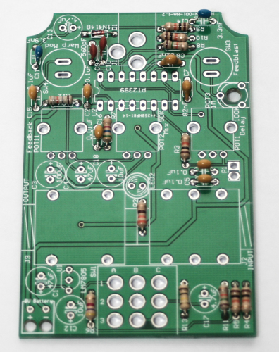
Cosmic Echo Ceramic Capacitors
Now populate the ceramic capacitors, then turn over and solder then clip the leads. Your capacitors may look a little different, so make sure you read the codes and follow the visual bom prior to soldering components.
HEADERS, IC SOCKETS, VOLTAGE REGULATOR & TRIMMER
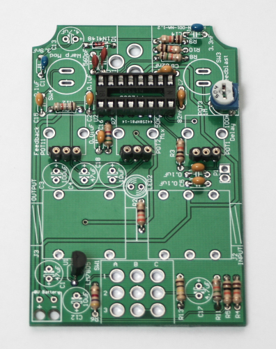
Cosmic Echo Headers and IC Socket
Now place the 3-pin metal headers in as shown above and carefully flip the PCB over and solder them into place. Notice that there is a plastic black sleeve that holds the header pins together. DO NOT overheat these while soldering as they will melt and be harder to use. Next place the IC Socket into place and solder on the back side of the PCB. Then orient the voltage regulator by matching the flat side of the transistor with the flat side on the white PCB silk screen graphic. Populate, solder and trim. Finally add the trimmer potentiometer (used to dial in the desired amount of ‘feedblast’ when the momentary switch is engaged), solder and clip.
ELECTROLYTIC CAPACITORS
Cosmic Echo Electrolytic Capacitors
Next, populate the electrolytic capacitors by lining up the longer lead (anode) with the ‘+’ marking on the PCB. Solder, then trim. Carefully align the notch on the IC with the notch on the socket and PCB silk screen.
AUDIO & DC JACKS
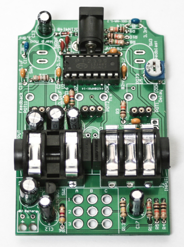
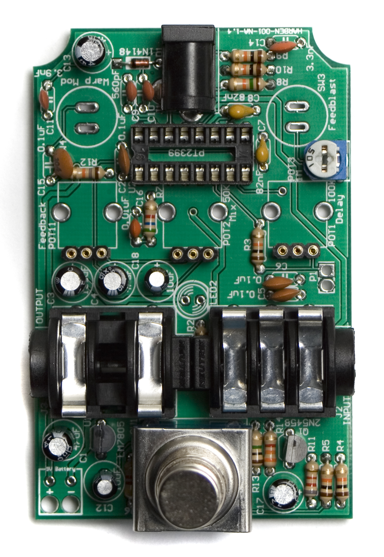
Cosmic Echo Jacks
First, populate the DC jack, turn over and solder. Then place the mono and stereo 1/4″ audio jacks on the their respective sides and solder them in.
9V BATTERY CLIP & IC PLACEMENT
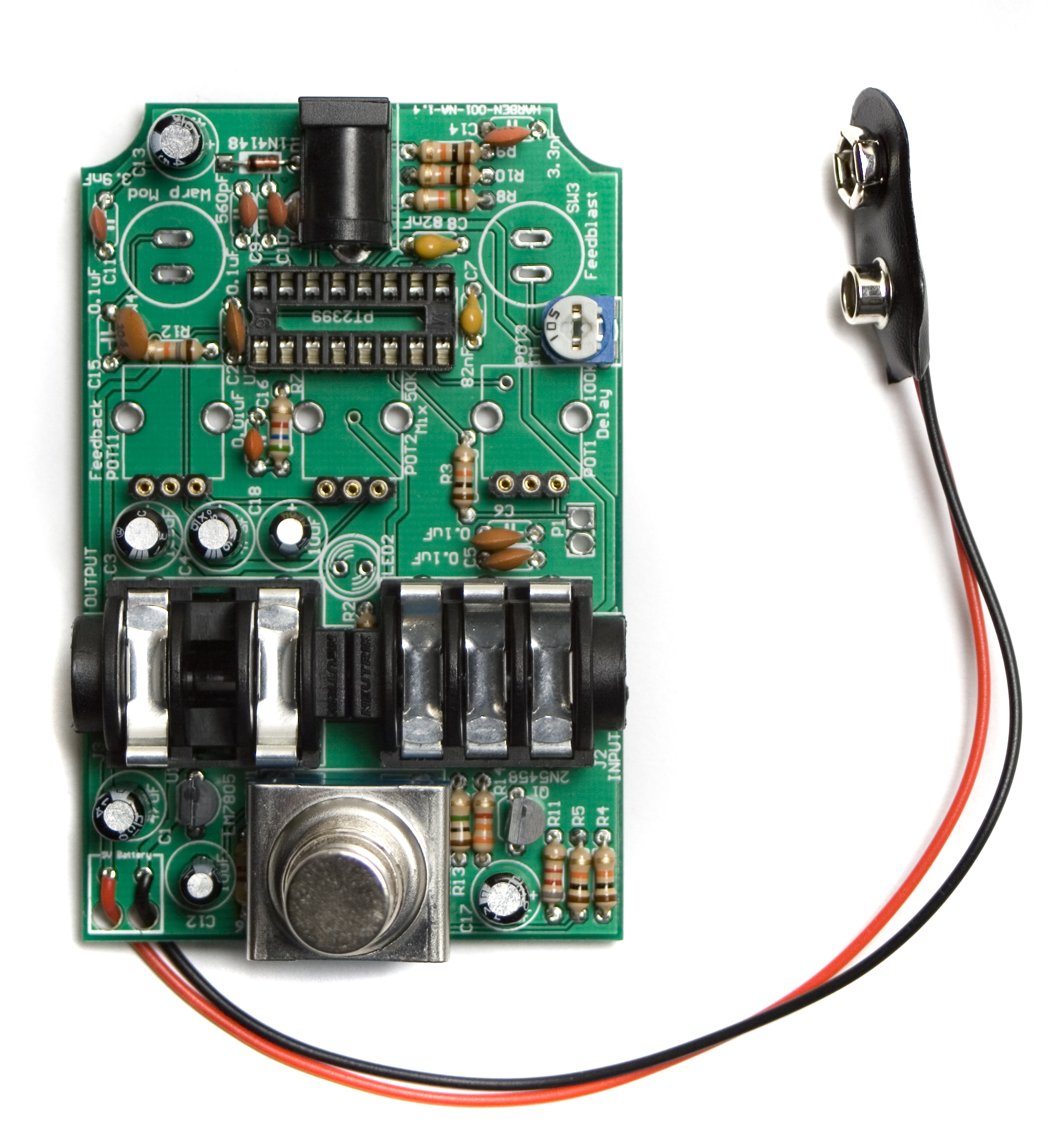
Cosmic Echo 9V Battery Clip & IC
Wire in the 9V battery clip as shown above and solder.
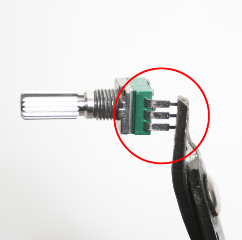
TRIMMING POTENTIOMETERS
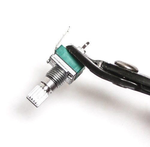
The 9MM potentiometers need to be trimmed in a few places to properly fit into this project. All 4 PCB mount clips should be cut to the base of the body of the potentiometer. Please see photos below:
Clipping Potentiometers
Also make sure that you clip the small alignment nub on top of the potentiometers so that the pots are not not canted when fitting into the enclosure.
Don’t forget to cut the nubs on the potentiometers as neccesary.
Next, cut apx. half of the thinner part of the potentiometer leads as shown below. This helps keep the height of the pots just right in order to fit into the enclosure.
Potentiometer Lead Clipping
PLACING & SOLDER POTS
Cosmic Echo Pot Placement
Now we want to place the trimmed pots (as shown above) onto the 3-pin headers. Before you try to solder the pots to the 3-pin heads it is advisable to add a small amount of solder to one of the pins of each header first. This will allow you to align the pots on place and hold down one pin before soldering the rest. This is the best method to avoid melting the 3-pin header. After this, solder the remaining pins as shown below.
Soldering 9mm Pots
Once you have successfully soldered the pots on, the project should look as it does below.
Cosmic Echo Pots Soldered
EXTENDING PUSH BUTTON SWITCH LEADS
The momentary push button switches on the Cosmic Echo are JUST long enough to be soldered into the PCB with the enclosure in place. If you are having any difficulty with this, please follow these optional instructions to extend the solder leads for an easier fit into the enclosure.
Momentary Switch Lead Extension
You will need a couple of spare trimmed resistor leads (4 total).
Momentary Hooks
Next, use some needle-nosed pliers and make a small hook on each lead.
Solder Leads to Switches
Now hook each lead to the solder lugs on the momentary switches, then solder in place. Make sure your hook eyelets are not too big as to now fit into the PCB.
ENCLOSURE INSTALLATION
LED for case assembly
Populate the LED into the PCB by lining up the FLAT side of the LED with the Flat indicator on the silk Screen (DO NOT SOLDER YET!). LEDs are polarized components and will only work if inserted the correct way. Allow the LED to remain unsoldered until you put the project into the enclosure.
Cosmic Echo Enclosure Switches
Now push the black plastic LED Bezel into the enclosure as shown above and take your two momentary switches and remove all of the nuts and washers. Then insert the switches into the switch holes and barely screw one of the nuts (per switch) onto the switch threads so that the switches are held down. Again, just barely. We will need as much of the switch as we can get if you did not follow the switch extension instructions. If you followed those instructions, you can use more of the switch threads.
Cosmic Echo Enclosure Placement
First make sure you have removed ALL of the washers and nuts from your 3PDT Stomp Switch. Now carefully (do not rush this or force anything) slide the project into the enclosure and push the LED through the bezel and bend the leads to mark your placement. Also make sure that your switch leads (if you followed those instructions) poke through the vias as shown below.
Switch Leads
Before you solder anything, tighten the Audio Jack Nuts on each side. This will help align the project into the case.
Add Audio Jack Nuts
Now solder the switch leads and LED leads and trim excess.
Cosmic Echo Switch Lead Soldering
Now add and tighten down the Pot and 3PDT Stomp Switch nuts (not too hard). Then you can gently tighten the momentary switches as well.
Tighten Nuts
CONGRATS!
You have assembled your Cosmic ECHO and are ready to shred. If you have any issues after putting the project in a case, carefully remove it and look for a connection that could have broken and repair. If everything is working fine, you can screw the enclosure backplate on and start to rawk! If you have any issues, please consult our TROUBLESHOOTING GUIDE.
BE SURE TO USE ONLY A 9V CENTER NEGATIVE POWER BRICK OR A 9V Battery.
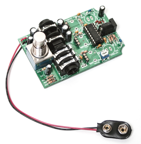
Finished Cosmic Echo
Optional Output Buffer Mod
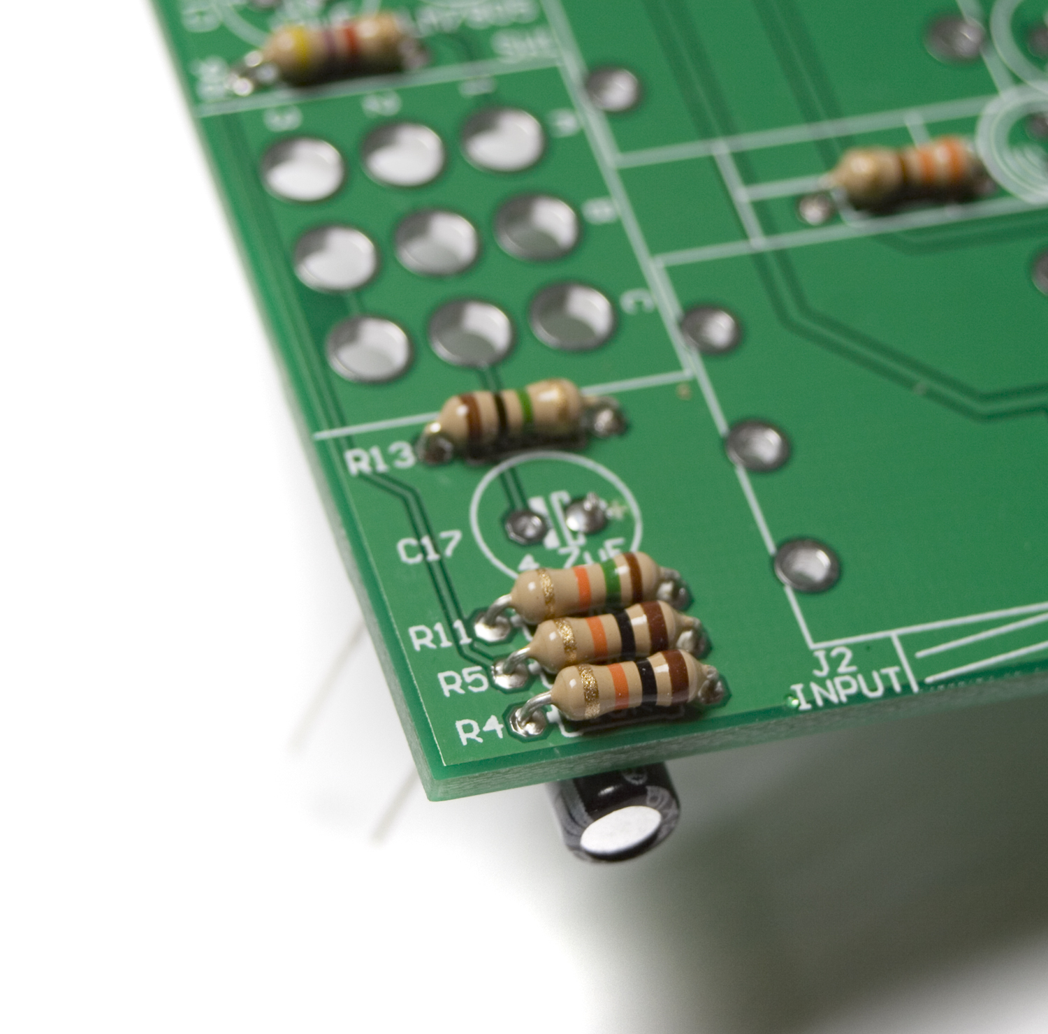
The first step before starting the buffer mod is populating all the resistors.
Cosmic Echo Resistors
Now flip the board over onto a hard surface and solder the legs in place. Clip all the leads EXCEPT R13.
R13 is NOT CLIPPED
Place the positive lead of C17 through From the bottom of the board like pictured below, but do NOT insert the negative lead through its hole. Just bend it straight up to get it out of the way for now. Solder the leads, but don’t clip them yet.
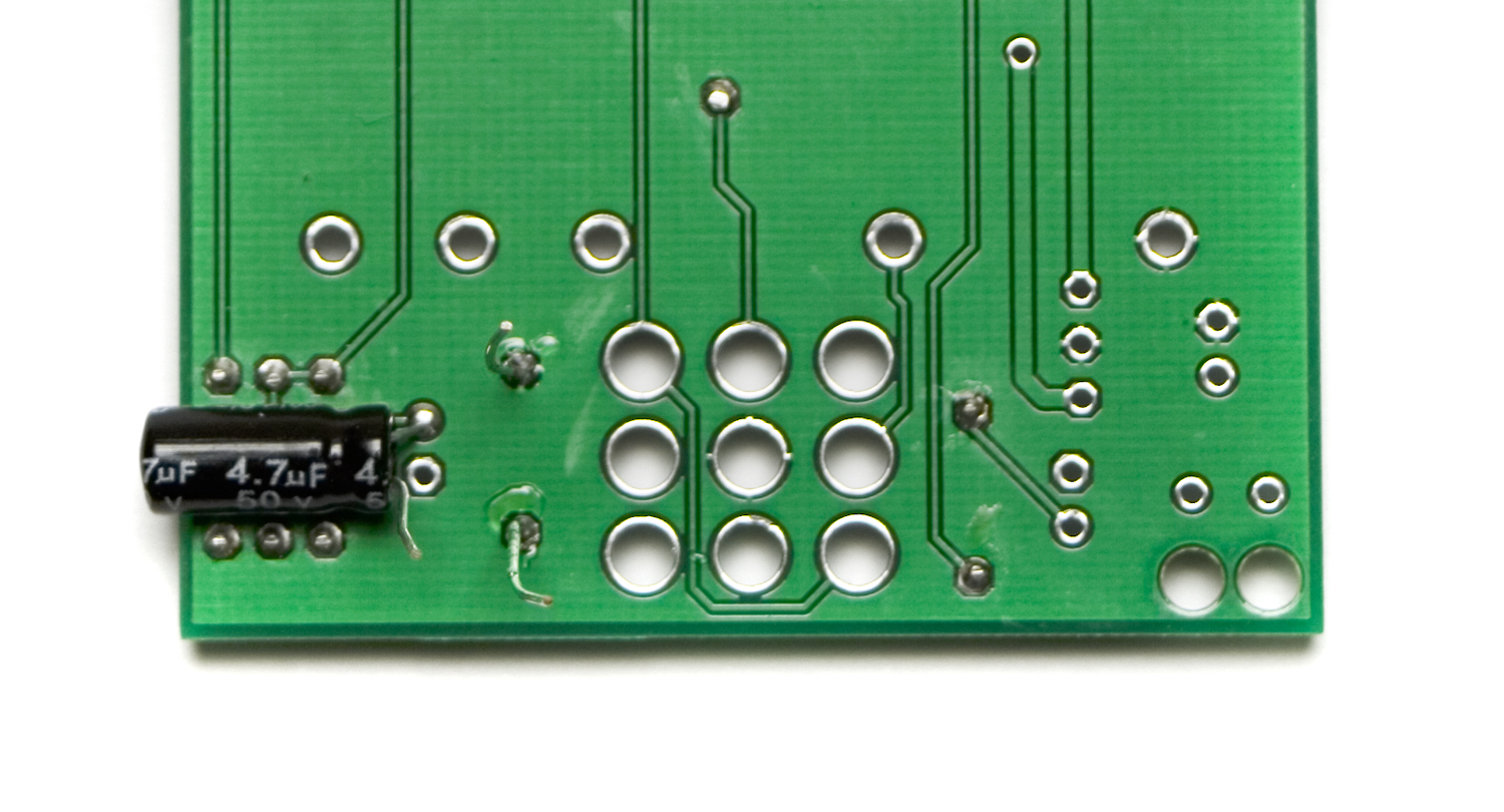
Capacitor Placement
C17 from the top side of the board.
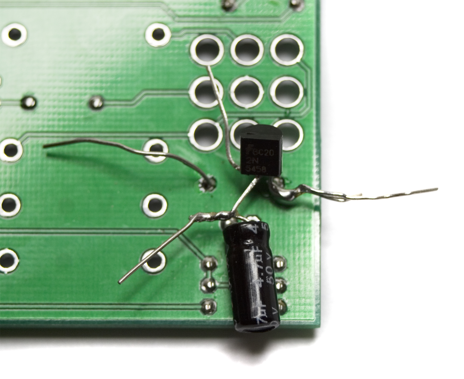
The next part is a little tricky, so make sure you have it right before soldering.

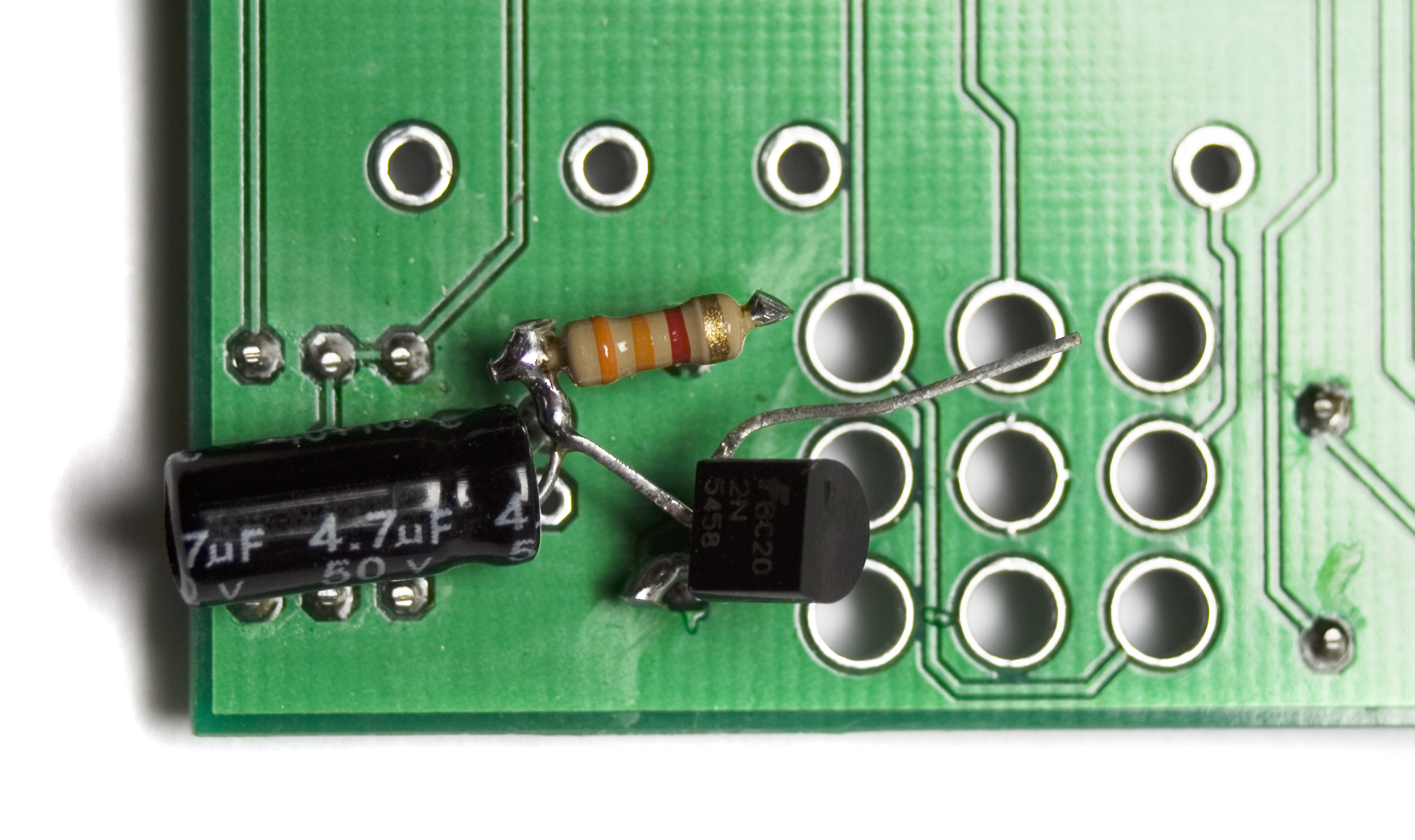
JFET Lead Orientation
Take the JFET, and twist the ‘Gate’ lead (G in the picture above) with the side of R13 that is closest to the edge of the board. Then twist the ‘Source’ lead (S in the picture above) of the JFET with the negative side of the capacitor. Bend the ‘Drain’ lead (D in the picture above) straight up (or off to the side) to move it out of the way for now.
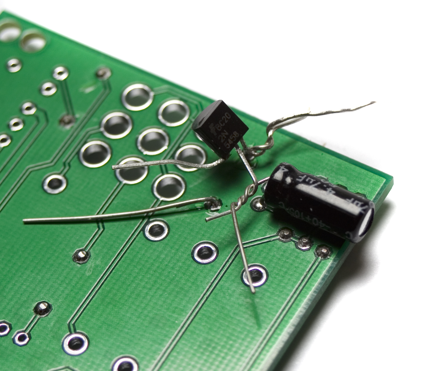
Now solder the leads. Don’t clip them just yet, though.
The Next step is to lay your 3.3k ohm resistor across the negative lead of the capacitor and the leg of R13 that you haven’t used yet as shown in the picture below.
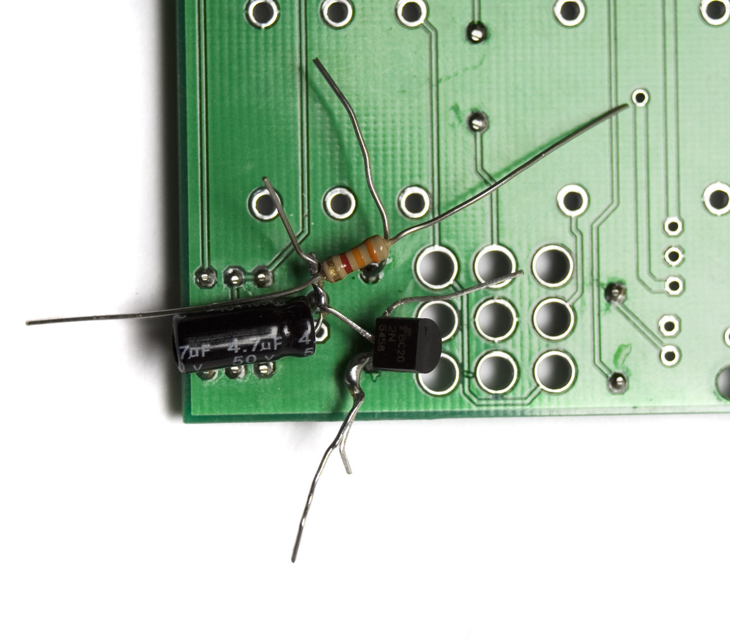
Now solder the resistor in place. You may need to enlist the help of someone to help hold the resistor in place while soldering.
Clip all excess leads at this point. DO NOT touch the ‘Drain’ lead of the JFET yet. This is where we will be soldering out +9v source.
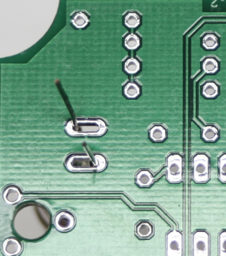
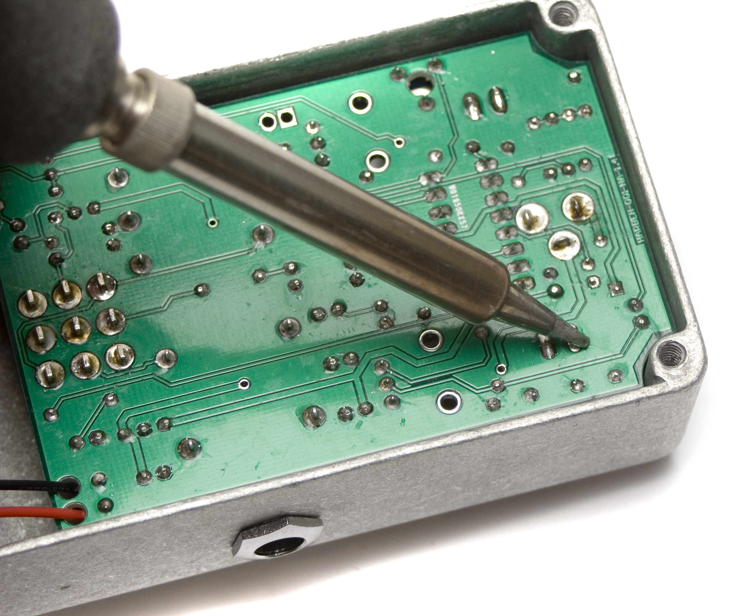
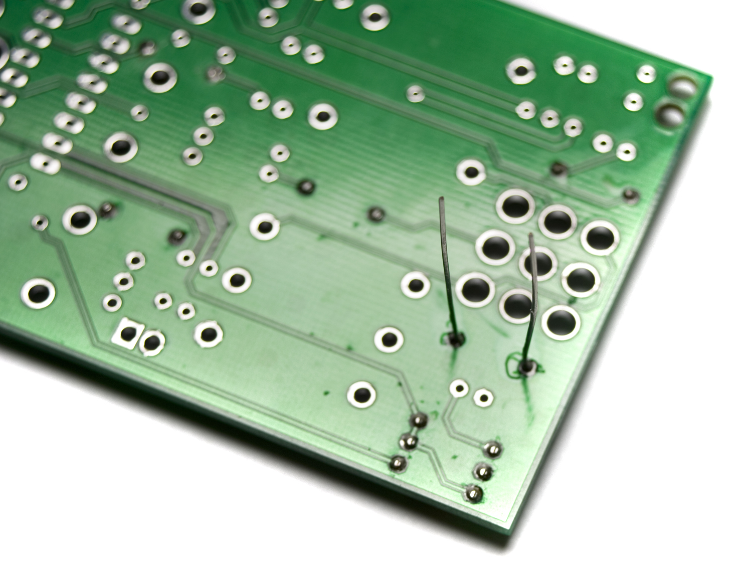
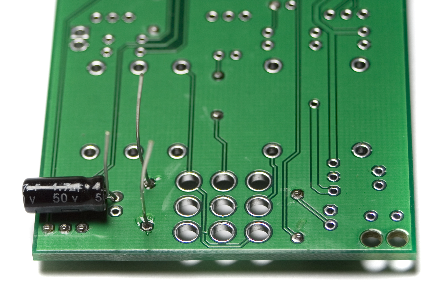
Next we will be soldering one side of the wire to the via that is in the middle of where the mono jack goes. Do this by stripping a little bit of casing off the end of the wire, and insert the bare wire through the via. (twist the wires first so they go in easier). Then solder it in place and clip any excess.
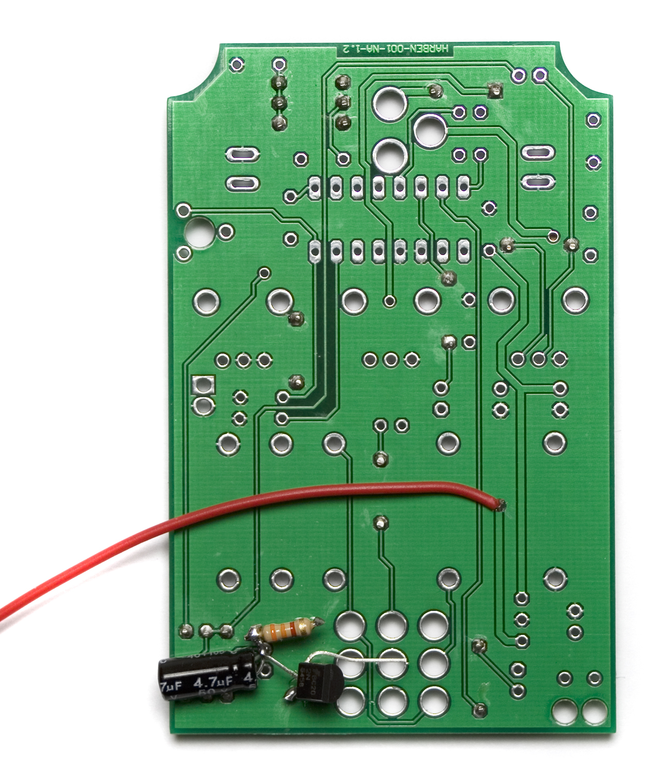
+9v Wire Location
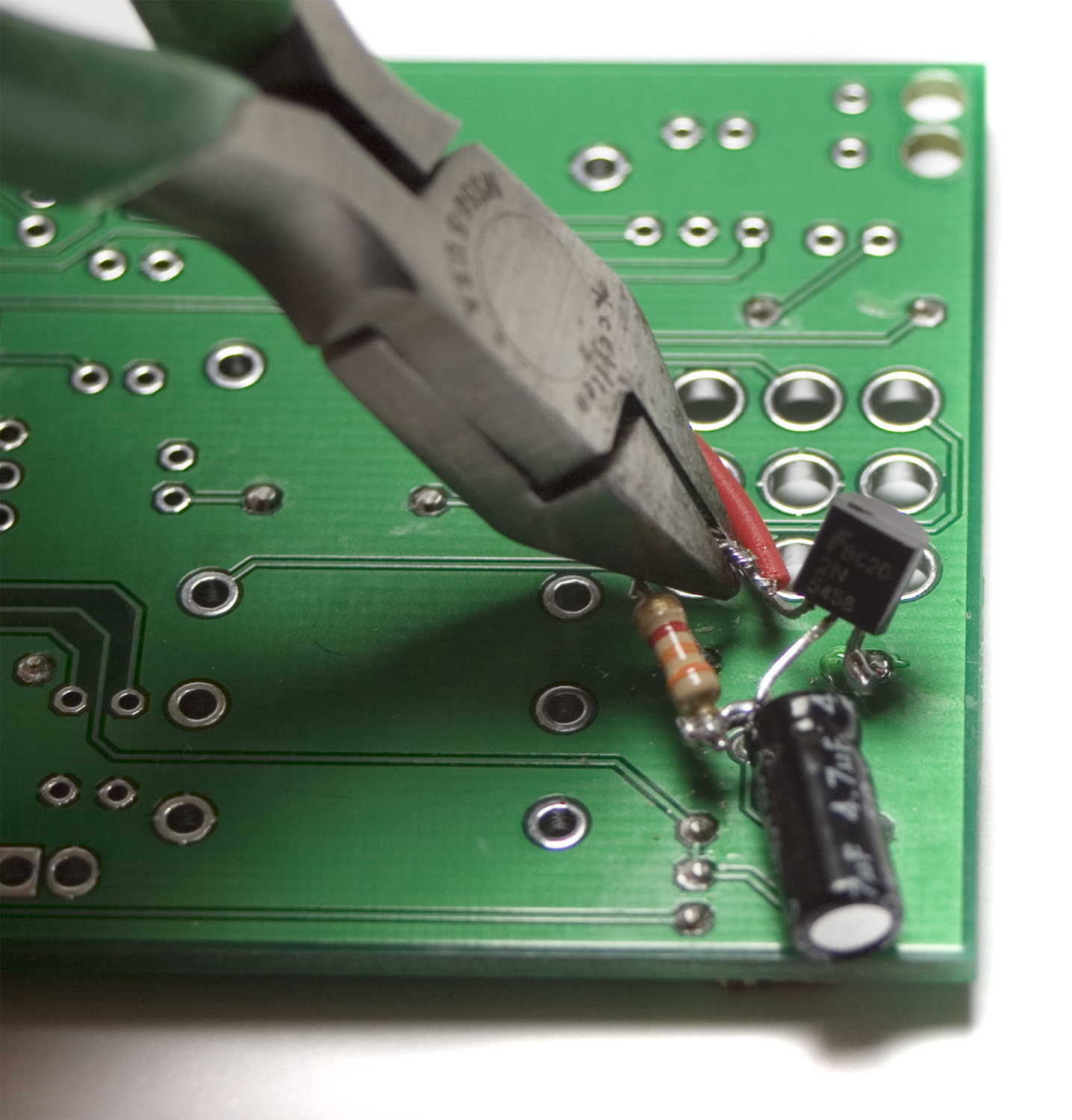
Next up, trim the wire down so it is short enough to not interfere with the rest of the build. Strip a little bit of casing off the end, and twist the bare wire around the ‘Drain’ lead of the JFET as shown below.
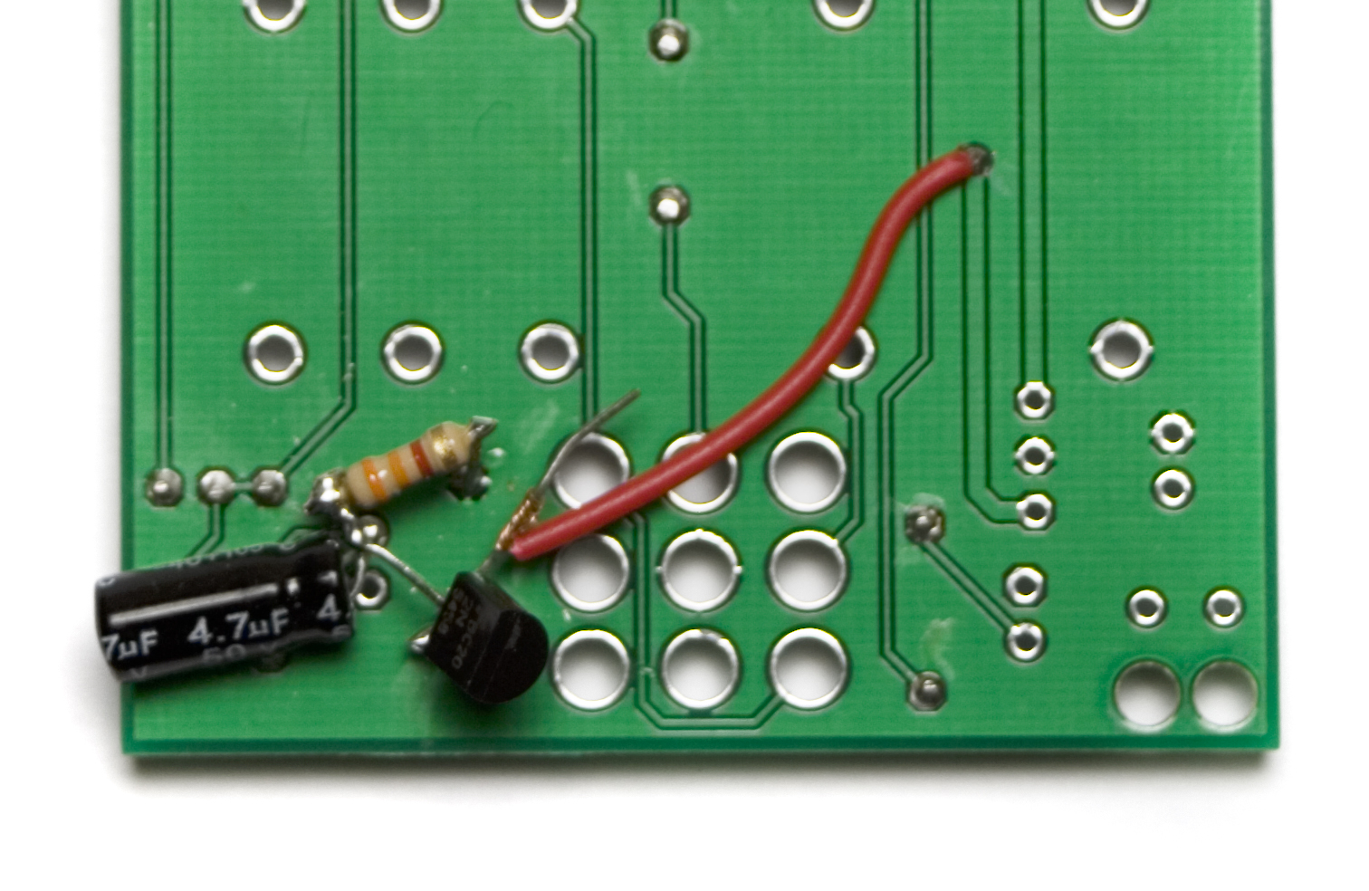
Twist the wire around the ‘Drain’ leg of the JFET
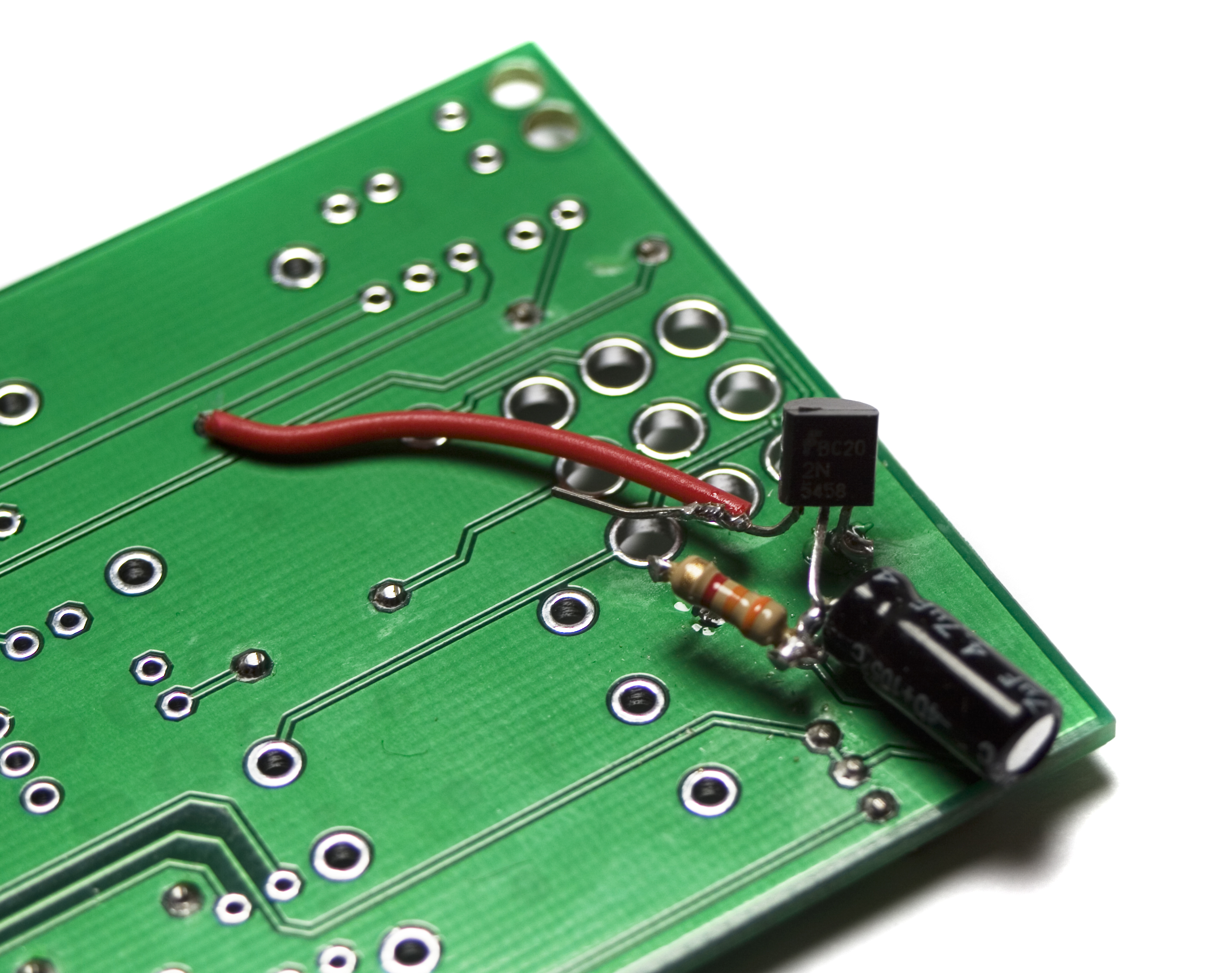
Another look at the JFET Wiring
Now you can solder the wire to the JFET and then clip the excess, as shown below.
You are now done with the output buffer mod for the Cosmic Echo. You may return to the top of the page, and continue following the instructions. Don’t forget to solder in your diodes from the first step before moving on.
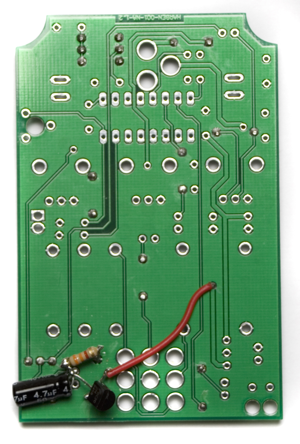
Completed Output Buffer Mod
hi there, is the schematic available for this kit, I am interested in buying one to modify for fitment into an existing effects panel but obviously don’t want the hassle of figuring out the circuit from the board as it will need to be built with a different power supply to run from 3.3v li-ion supply and the switch gear will be different, many thanks, carl
Hey Carl,
Due to different licensing agreements, we are not able to make all of our schematics available to the public.
Are you looking to mod the circuit so it will run off a 3.3v li-ion supply?
Thanks
-Zach
Hi,
I purchased just the PC board and Im having a bit of an issue. I have a situation where when power off i’m getting sound through but when I turn on the switch i have no sound coming out of the unit other than residual effect. I’m getting effect because I can adjust in and out with the feedback and i hold down the switches and that effect comes in with no issues either just none of the audio from the input. I have checked all solder joints under a magnifying glass and all is well there.
Any idea what i can look into? And i know you had mentioned before you don’t share you schematics but it would sure help in troubleshooting….
Thank you for your time.
Dave
Hey Dave,
If you could send us over some pictures of your board to store@synthrotek.com I can help you to troubleshoot your Cosmic Echo.
Because the pedal is true bypass when inactive, it will let signal pass. However, when you turn it on it will rout your signal through the circuit. Once I get a look at your boards I will follow up with some test advice and repair suggestions
-Zach
Having a hell of a time trying to troubleshoot the popping I get when engaging the pedal. And I can’t find anything on the web about where I can add some pull down resisters. You guys have any suggestions? Please help everythinnng about this pedal is awesome just gotta get rid of the pop.
Hey Ben,
I looked around for some more information on the subject and found this quick explanation of what contributes to the pop. If you’ve already seen this before send us a message at store@synthrotek.com and we can try and get you set-up with a comprehensive mod guide for getting rid of pop:
http://www.mercyseateffects.com/pop-goes-the-effects-pedal-how-to-fix-that-annoying-sound/
As mentioned in the article, the pop is typically from big voltage changes – this could be caused from the LED, however I would try the more simple RC filters suggested in the article.
Let me know how it turns out!
-Zach
Got the pop sorted it was a bad solder joint to ground on the suggested mod. You guys should probably put the additional buffer mod instructions at the top of this page. It was a bummer to get through following the instructions casing the whole thing and then find out about the “mod” at the bottom of the instructions and have to back pedal and desolder. just a suggestion. my board looks like frankensteins monster after burning up pads and having to run wire.
on the BOM for verson 1.4, r13 says 100k on the board, the mouser part number is for a 100k resistor but the value on the BOM is 1M. Which value supersedes the others?
Hello, sorry for the confusion. Go with the BOM and insert a 1M resistor. I’ve updated the Mouser number.