Thank you for purchasing the Synthrotek MIXIV four-channel mixer kit! This is an intermediate to advanced build as it is requires surface mount (SMD) assembly. These parts are VERY small and easy to lose, or install incorrectly without experience. It is very important to get all the components properly soldered into the PCB in the correct placement. If you feel like you can handle it, please proceed! If not, get some help from a friend with experience or purchase a fully completed unit.
Please build according to the BOM, and not these instructions or the pictures alone. Some components may have changed since these were written, or we may not be able to get the exact looking components in the pictures.
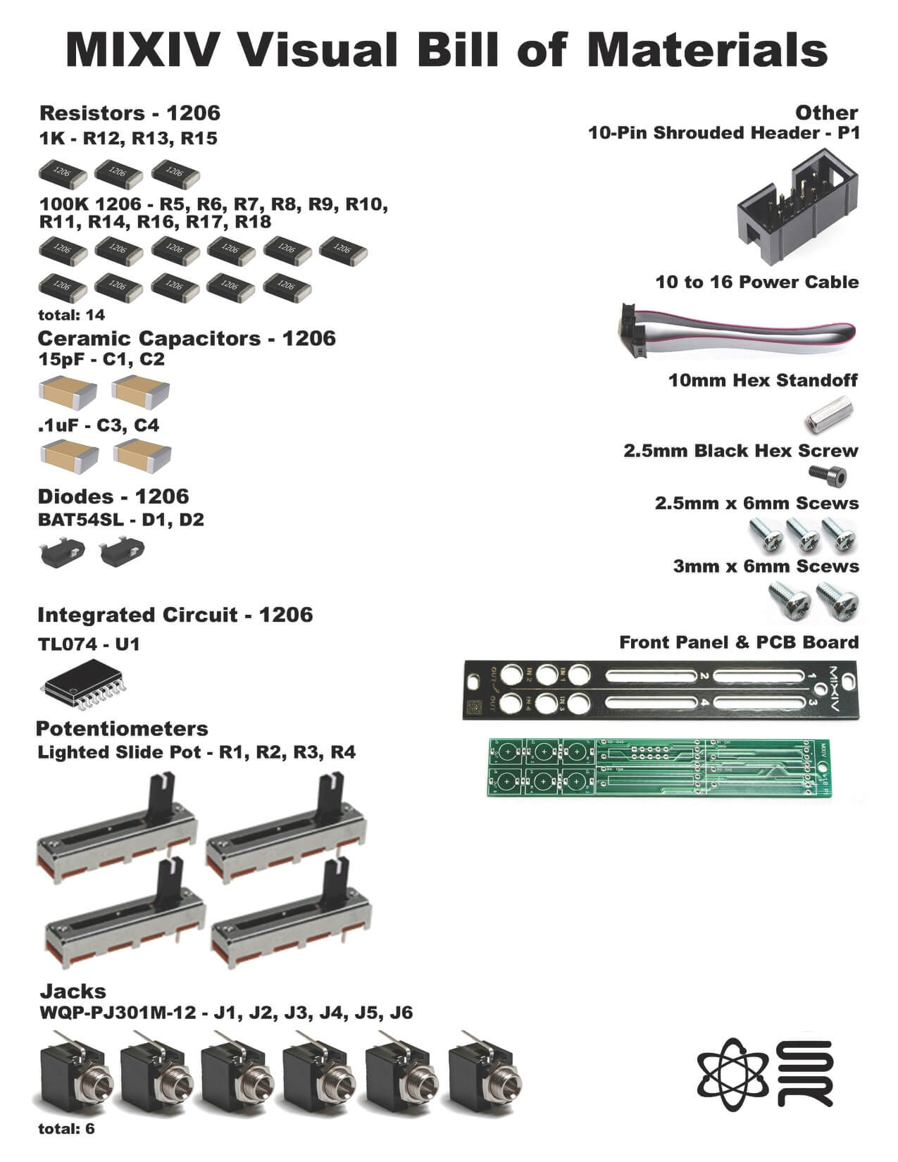
For a Bill of Materials with the part numbers included, click here.
General Advice on SMD Soldering
SMD soldering is a different beast compared to through hole soldering. We encourage you to take extra time keeping the components in their own place and be diligent, slow and precise as you open up the packaging containing these very small components.
We suggest adding a small amount of solder to one of the pads that you will be working with PRIOR to placing the component. Using a good pair of tweezers, place the component on the pads and carefully reheat the solder on the pad that was tinned. If the placement looks good, then go ahead and solder the component to the other pads.
recommended tools:
- small tweezers
- magnifying lens
- fine soldering tip
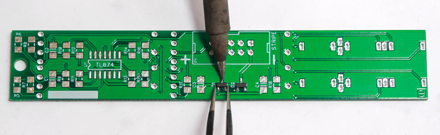
Diodes
We will start off my placing the two diodes on the PCB as shown below. Add some solder to one of the pads prior to placing the component. Just a very small amount is all you need. You can then use tweezers to hold the component in place while tacking down the pad that had the solder added.
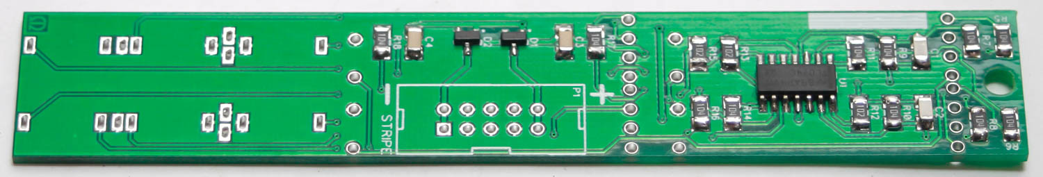
Resistors, Ceramic Capacitors and IC
Resistors and ceramic capacitors are not polarized and can be placed either direction. Add a very small amount of solder to one pad then carefully place the component and tack down one side with your soldering iron. Add some solder the other side of the component and pad.
Align the stripe on the IC toward the callout, U1. Add a very small amount of solder to one pad then carefully place the component and tack down one side with your soldering iron. Now do one of the legs on the other side, then solder the rest of the legs.
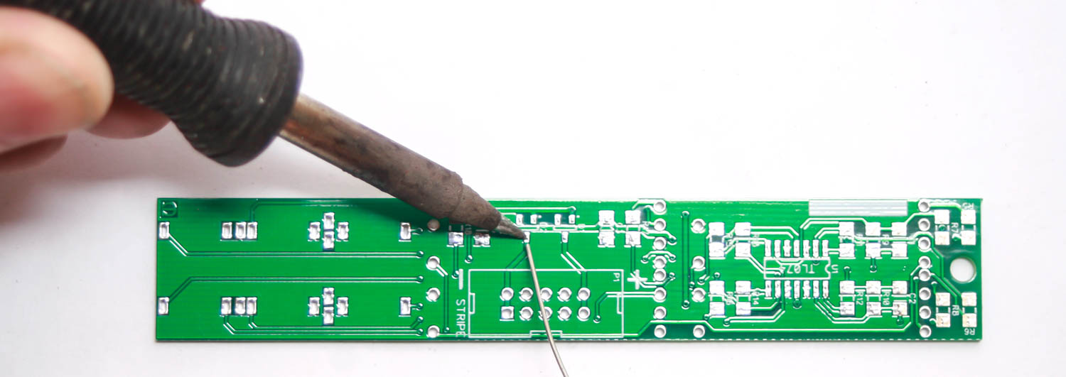
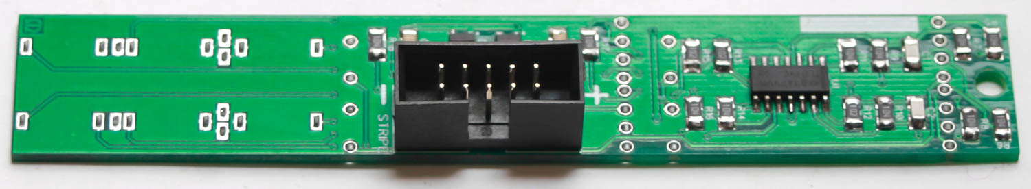
Power Header
Place the 10-pin power connector into the PCB by aligning the notch on the connector with the notch on the PCB silk screen. Carefully turn the project over and solder the pins in place.
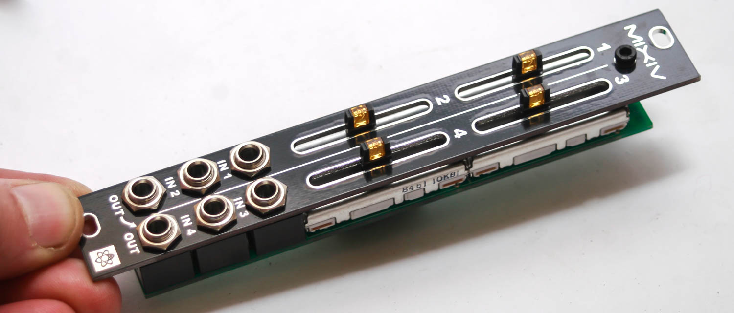
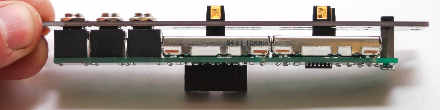
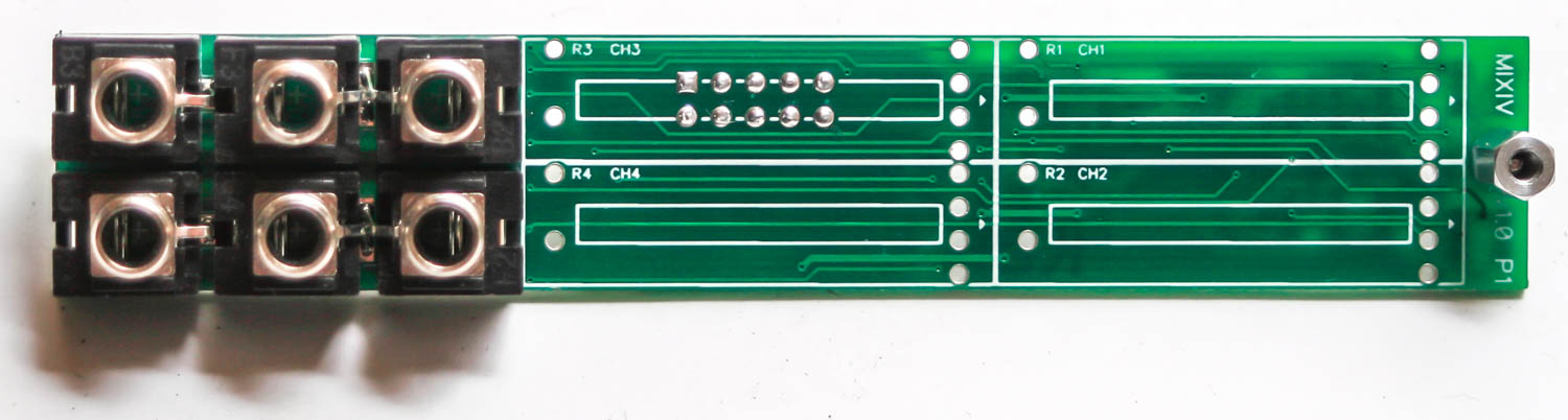
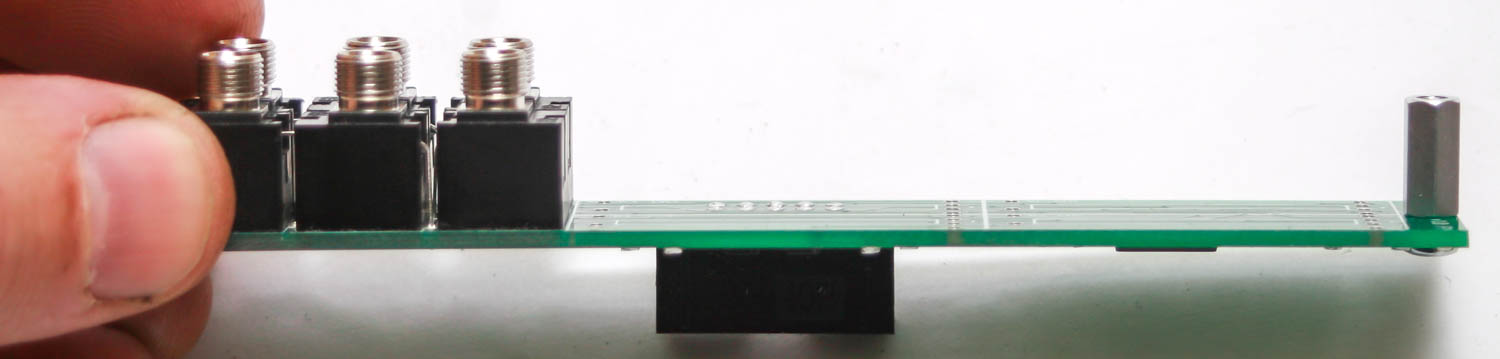
Jacks & Standoff
Take the standoff and the standoff screw and secure it to the front side of the PCB as shown below. Next carefully place all the 3.5mm jacks into the PCB as shown below.
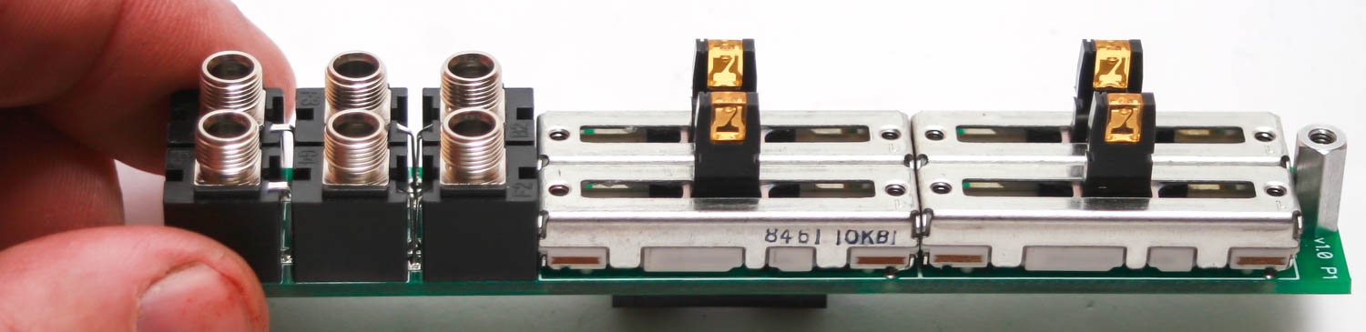
Slide Potentiometers
Add the slide pots as shown below. Make sure that the pins on the shrouded header are not bumping into the slide pot; if they do, trim them down a little. Wait to solder until front panel placement.
Front Panel & Final Soldering
Now take the panel and carefully place it over the project. Hand-tighten the jack nuts and the black 2.5mm standoff screw. Once tight, carefully turn over the project and solder the jack and potentiometer leads. Tighten the jacks and standoff screw a bit more with tools if needed. Now you are ready to test it out!