


Important Links
Product Page
Store Page
Assembly Instructions
Bill of Materials
Capacitor and Resistor Lookup Guide
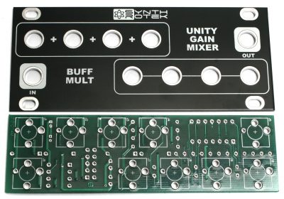
Thank you for purchasing the Synthrotek purchasing the 1U UniBuffer Kit! This is an intermediate build as it has many stand-up resistors and tight soldering. If you feel like you can do it, please proceed! If not, get some help from a friend with experience or purchase a fully completed unit.
These assembly instructions show the PulpLogic format version of the module, but the build order will be the same if you purchased the 1U Multiformat version.
ATTN: Please follow the BOM and these instructions and don’t populate from the PCB alone. Also sometimes we cannot get the exact pictured components, so please look over your parts and check the codes first. Lets begin!
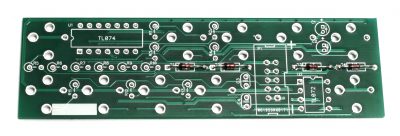
DIODES
Start with the diodes as shown below, then set over a firm surface to solder, then clip your leads. Diodes are polarized components so you must match the black stripe on your diodes with the white stripe on the PCB silkscreen.
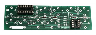
IC SOCKETS
Place the IC sockets by aligning the notch with the notch graphic on the PCB silkscreen. Turn over on a flat surface and solder into place.
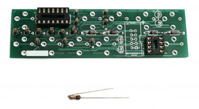
RESISTORS
The resistors on this build need to be installed standing up. It is helpful to bend over one of the resistor leads first before populating each resistor. Solder and clip leads.
CAPACITORS
Add the non-polarized capacitors as shown below. Next, make sure you orient the electrolytic capacitors in correctly. The longer lead needs to be inserted into the hole that has the “+” marking near it. Turn over to solder and clip leads.
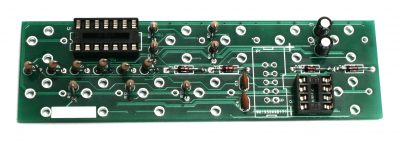
10-PIN POWER HEADER & IC
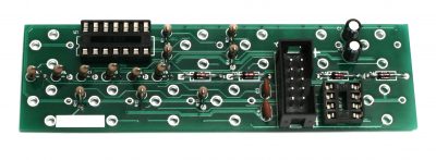
Next add the 10-Pin Eurorack Power Connector in place by matching the key notch with the key indicator on the PCB silk screen. Turn over and solder on a flat surface. Then add the IC by aligning the notch of the IC with the notch on the header and pcb silkscreen.
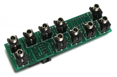
JACKS & PANEL
Now place the jacks on the other side of the PCB as shown below (do not solder just yet!)
Now marry the PCB and the panel. The panel can accidentally be oriented upside down, so make sure that the serial number on the PCB faces downward. The serial number on the PCB should be behind the buff mult part of the panel.
Fully tighten (not too tight) the jack nuts as shown below:
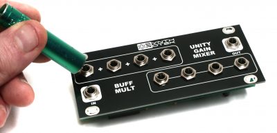
1U Unibuffer Jack Nuts
You can now solder the jacks in place. After you have soldered all of the jacks you are ready to test your module!
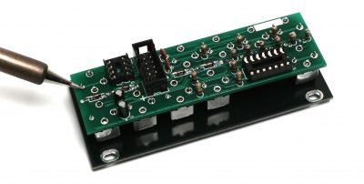
1U Unibuffer Jack Soldering
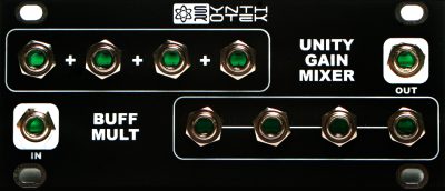
TESTING PROCEDURE FOR UNITY GAIN MIXER
There are 4 inputs that are capable of mixing / summing AC signals (audio) and/or DC signals (gates, triggers, CV).
TESTING WITH AC
Start by plugging in an AC signal from the OUTPUT of an oscillator, sampler, percussion module, or any other module that outputs audio into the UNITY GAIN MIXER’s INPUT section (top left of module). Take a second AC signal plug it into the next INPUT on the UNITY GAIN MIXER. Both signals should now be summed together, and you can monitor this by taking the OUTPUT and running it into the INPUT on a mixer. Now test the other 2 available INPUTS on the UNITY GAIN MIXER by either moving the two AC signals over or by plugging in two other AC signals from other sources.
TESTING WITH DC
Start by plugging in a CV signal from an envelope, LFO, sequencer, or a MIDI to CV module into the UNITY GAIN MIXER’s INPUT section. It is best to start with the jack on the far left side. Take a second DC signal and plug it into the next INPUT on the UNITY GAIN MIXER. Both signals should now be summed together, and we can test this by running the OUTPUT into the 1V/O INPUT on an oscillator and monitoring the frequency changes that the summed DC signals are causing. Now test the other 2 available INPUTS on the UNITY GAIN MIXER by either moving the two DC signals over or by plugging in two other DC signals from other sources.
By now you should be able to confirm that all INPUTS and OUTPUTS are working correctly on the 1U UNIBUFFER and that the UNITY GAIN MIXER section is working correctly with both AC and DC signals.
TESTING PROCEDURE FOR BUFF MULT
TESTING WITH 1 OSCILLATOR
Plug a cable into a 1V/O INPUT on an Oscillator and plug the other end of the cable into one of the BUFF MULT’s OUTPUTS (bottom right section). It is best to start with the jack on the far left side. Make sure that each of the 4 OUTPUTS are all making precise copies of the INPUT signal by monitoring your Oscillator’s OUTPUT.
TESTING WITH MORE THAN 1 OSCILLATOR
Plug a cable into a 1V/O INPUT on Oscillator #1 and plug the other end of the cable into one of the Buff Mult’s OUTPUTS. Plug a cable into a 1V/O INPUT on Oscillator #2 and plug the other end of the cable into one of the other available OUTPUTS.
From here it’s best to get both Oscillators in tune with each other so you can hear them both reacting the same way to the INPUT signal. Make sure that each of the 4 OUTPUTS are all making precise copies of the INPUT A signal by monitoring the OUTPUTS from both Oscillators #1 and #2.
By now you should be able to confirm that all INPUTS and OUTPUTS are working correctly on the 1U UNIBUFFER and that the BUFF MULT section is working correctly.
If you have any questions or need help debugging, please first refer to our troubleshooting guide BY CLICKING HERE. If this gets you nowhere, please contact us by email for support. Thank you again for purchasing your kit from Synthrotek!
Final 1U Unibuffer