


Important Links
Quick Start Guide
Product Page
Store Page
Assembly Instructions
Bill of Materials
Capacitor and Resistor Lookup Guide
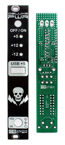
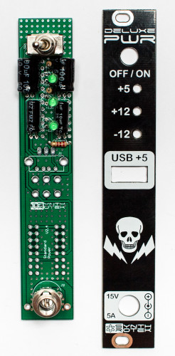
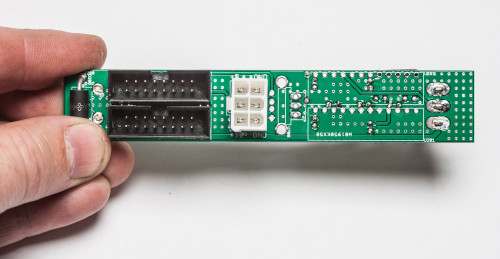
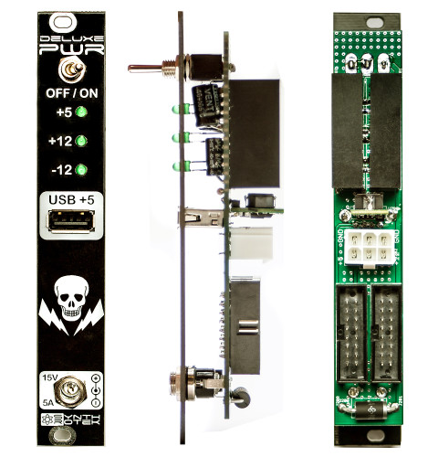
Deluxe Power Front Panel & PCB
Thank you for purchasing the Synthrotek Deluxe Power Eurorack Module. This is a VERY ADVANCED build. You will need a fine tip soldering iron, a very steady hand and experience. If you feel like you can handle it, please proceed! If not, get some help from a friend with experience or purchase a fully completed unit.
ATTN: Please follow the BOM and these instructions and don’t populate from the PCB or these instruction pictures alone. Also sometimes we cannot get the exact pictured components, so please look over your parts and check the codes first.
Let’s begin!
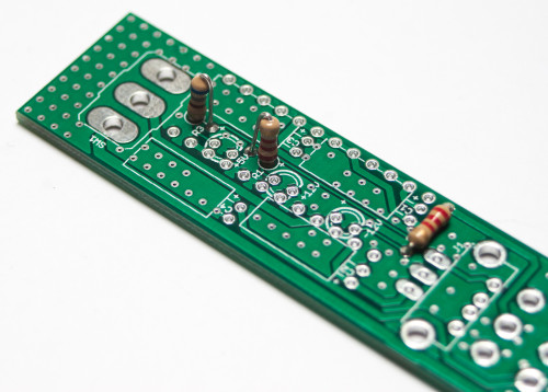
RESISTORS
Populate the flat resistor first, then turn over on a firm surface to solder and clip leads. Then bend over the leads of the two remaining stand-up resistors, turn over to solder then clip leads.
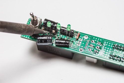
ELECTROLYTIC CAPACITORS
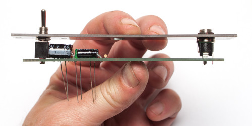
Next, make sure you orient the electrolytic capacitors in correctly. The longer lead needs to be inserted into the hole that has the “+” marking near it. Fold the caps down as shown above. Solder and clip.
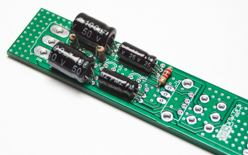
Deluxe Eurorack Power Capacitors
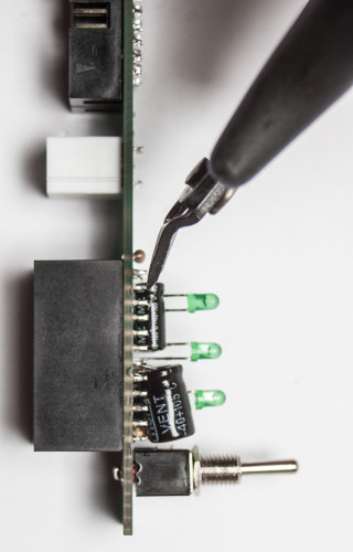
DC JACK, LEDs and SWITCH
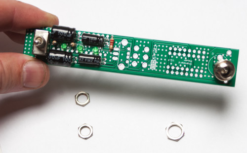
Deluxe Eurorack Power Supply DC Jack and Switch
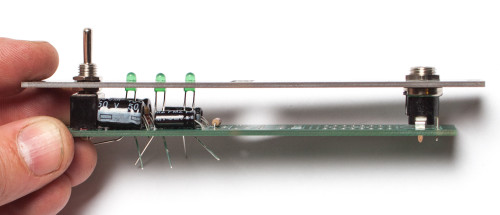
It is very important to now align the DC Jack, ON/OFF Switch and the LEDs with the pane. First, start by placing the LEDs in their pads carefully. There are a lot of small holes, so take your time and do this carefully. LEDs are polarized components, make sure you place the anode (longer lead) into the pad with the ‘+’ marking next to it. Now remove ALL the nuts and washers off of the switch and DC Jack and place them (do not solder anything yet!) on the PCB.
PANEL ALIGNMENT
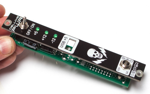
Take ONE of the switch nuts and screw it down onto the shaft of the switch to around the area shown below so that the panel and board are parallel, then take the panel and place it over the DC Jack and Switch.
Synthrotek Deluxe Eurorack Power Supply Panel Alignment
Now gently tighten down the other switch nut and the DC Jack Nut, turn over and solder in place. After that, push the LEDs up into their respective holes and solder them in place and trim leads.
Synthrotek Deluxe Power Supply Panel Placement
Pushing LEDs In place
Soldering DC JACK, SWITCH and LEDs
Clip the DC JACK leads fairly close to the PCB to leave room for the diode.
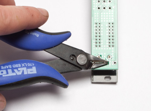
Clip DC-JACK Leads
The DC Jack, Switch and LEDs are aligned to the panel. You will now need to unscrew the nuts and remove the panel in order to complete the build.
Remove Panel
DIODE
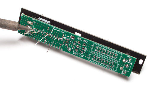
Insert the diode as shown below, then turn over on a firm surface to solder, then clip your leads. Diodes are polarized components, so you must match the sliver stripe on your diode with the white stripe on the PCB silkscreen.
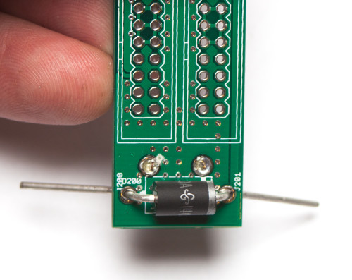
DIODE
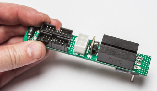
POWER CONNECTORS
Next add the 16-Pin Eurorack Power Connectors in place by matching the key notch with the key indicator on the PCB silk screen.
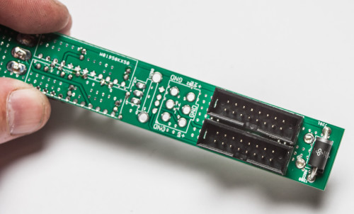
16-Pin Eurorack Power Connectors
OPTIONAL MOLEX CONNECTOR
Synthrotek’s new power systems use 6-pin Molex connectors to connect our Eurorack Distribution Boards to the power module and also to daisy chain distro boards together. This is, however, optional. If you want to “hard-wire” your wire directly, then omit this part and solder the wire directly to the board. You also do not need this part if you are going to always use flying bus cables, but it won’t hurt in case you upgrade in the future.
MOLEX Power Connector
12 VOLT CONVERTERS
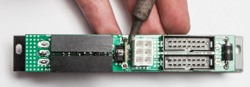
Synthrotek uses very high quality and ultra-efficient power converters which are the most expensive part of your module. Please take this next part carefully. Place the two 12 volt converters (they are DIFFERENT! PLEASE SEE THE PHOTO BELOW) in the PCB and solder in place. THIS IS TRICKY as the project is very densely populated at this point. Please use a fine tip on your soldering iron and proceed carefully. Feel free to gently move the caps out of the way a bit while soldering.
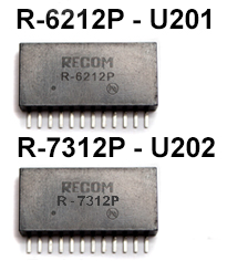
DC to DC Converters
12 volt DC converters
Clipping Leads
Carefully clip the leads if possible. You will need small fine clippers.
Next, add the 5V converter as shown below, turn over and solder into place.
5V Converter
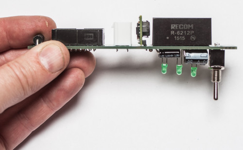
Orientation of 5V Converter
FINAL PANEL PLACEMENT
Now place the panel back on the project and gently tighten down the DC-JACK nut and Switch nuts in place.
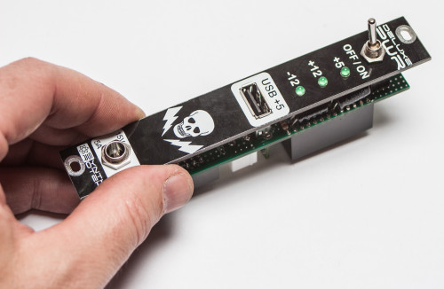
Placing Panel
You will now press the USB jack through the panel and turn over and solder in place. It can help to gently bend the USB alignment clips in a bit before you place the jack through the hole.
USB Alignment
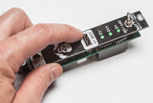
Soldering the USB JACK
BE CAREFUL WHEN SOLDERING THE USB JACK!
It is a very tight area.
CONGRATS! you have now finalized your Deluxe Eurorack Power Module! You can now plug your DC power brick plug into the DC Jack and flip the power switch to “ON”. All 3 green LEDs should light up. If you are having any issues please consult our TROUBLESHOOTING GUIDE.
Thanks for choosing Synthrotek!
FINAL DELUXE POWER
R4 is listed as optional in the BOM, but isn’t listed in the assembly instructions. Should I just populate it? It’s easy to add at the end so I haven’t yet put it in. The build took me about half an hour and everything worked out great. I’ll definitely be ordering some other kits! Thanks.
Hey Jesse,
Happy to hear your enjoy our kits!
R4 was recently added to the board in order to get it to work with iPhones. This is why it is optional. It will power/charge most everything else but for whatever reason (most likely due to impedance), iPhones need the that component to charge.
Keep up the good work!
-Zach
maybe i am missing something? For what are the 2.5mm screws good for (thay are in the BOM)? And: is it correct, once the USB connector is soldered, there is no way anymore to remove the panel.
Depending on what type of rails you use, the 2.5mm screws are meant for mounting your module to 2.5mm square nuts or nuts strips. For example, the rails and Eurorack cases sell have 2.5mm threads and call for 2.5mm screws in order to mount modules. Other companies use 3mm screws. We provide both options with our products.
-Zach