Important Links
Product Page
Store Page
Assembly Instructions
Bill of Materials
Quick Start Guide
Capacitor and Resistor Lookup Guide
Thank you for purchasing the MST Ribbon Controller kit! This is an easy build. It is very important to get all the components properly soldered into the PCB in the correct placement. If you feel like you can handle it, please proceed! If not, get some help from a friend with experience or purchase a fully completed unit.
Please build according to the BOM, and not these instructions or the pictures alone. Some components may have changed since these were written, or we may not be able to get the proper components in the pictures.
Lets Begin!
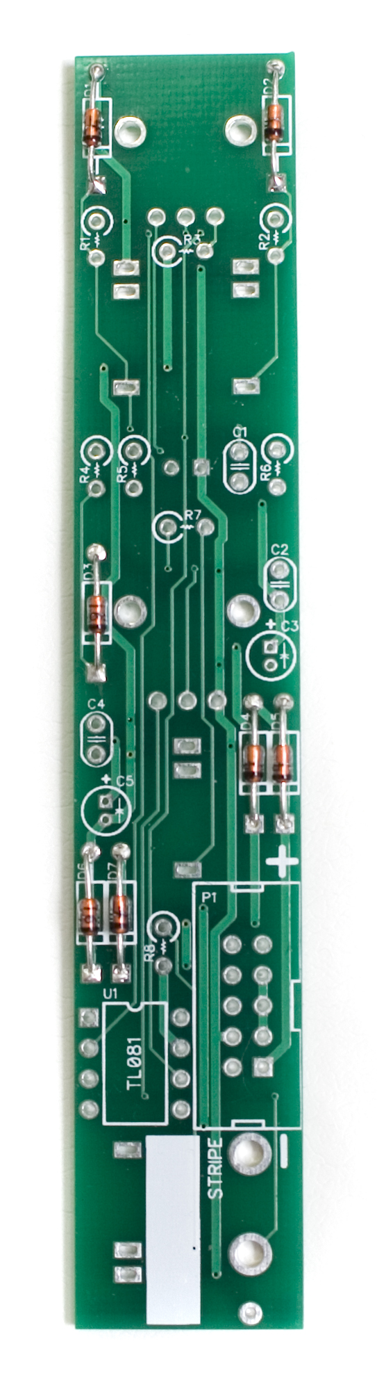
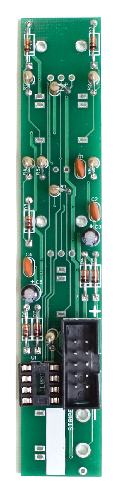
 Diodes
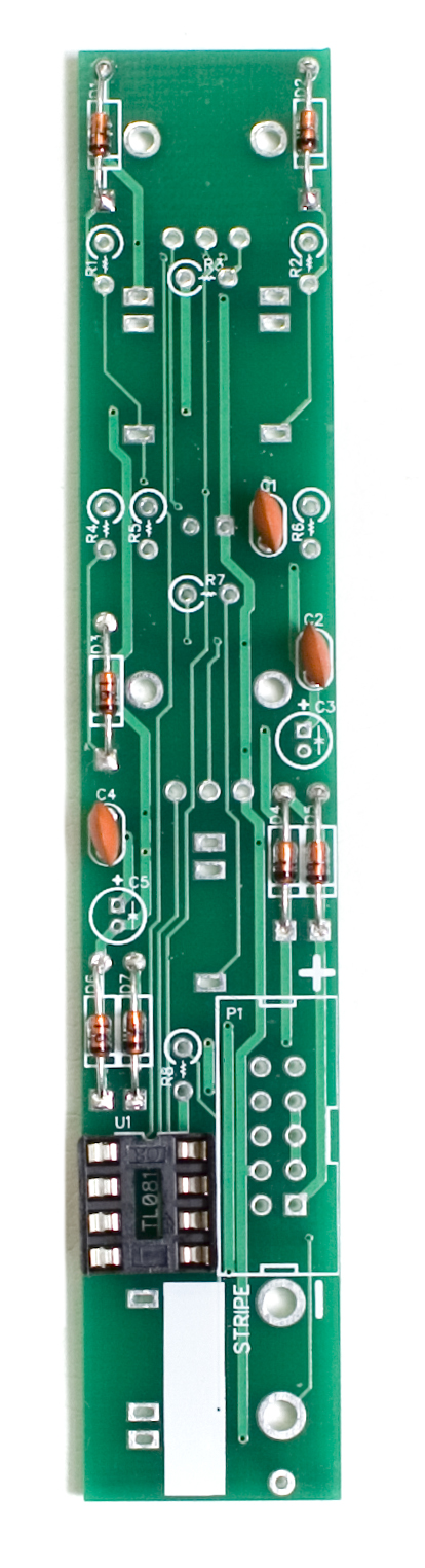
First up are the diodes. These are polarized, so make sure when you are populating them to get the cathode band (black stripe) aligned in the same orientation as indicated on the PCB by the stripe. Once they are populated, flip the project over, and solder them in place, clipping the excess leads. You will need to save at least one of these clippings for the stereo jack later in the build.
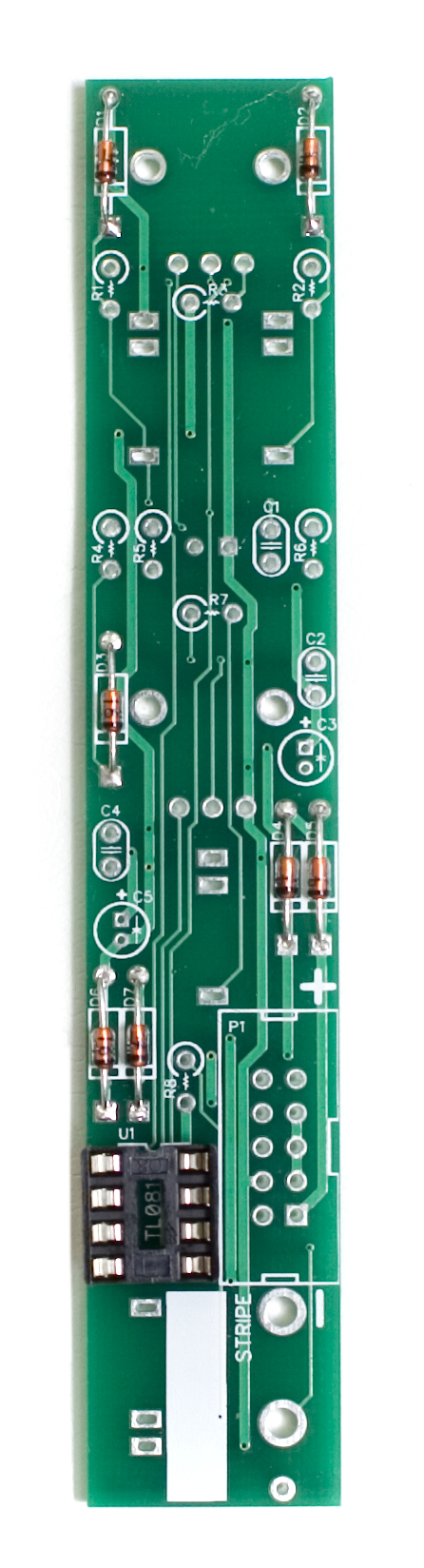
 IC Socket
Next up is the IC socket. The IC socket has a semi-circular notch in one end that indicates pin1 on the IC, so it is important to make sure it is lined up properly. Put the side of the socket with this notch facing in the same direction as indicated on the PCB (towards the top of the PCB). Carefully flip your project over and solder it in place. In order to get it nice and flat, you can solder just one leg of the socket, then while applying gently pressure, reflow that solder joint so that it sits flat. Then go back and solder the remaining pins.
 Ceramic Capacitors
Now we can move on to the ceramic capacitors. These are non polarized, so it doesn’t matter which direction you populate them, but it will help with any troubleshooting that may arise if you populate them in a way that they can be easily read once the module is completed. When they are all populated, carefully flip your project over and solder them in place, clipping the excess leads.
 Electrolytic Capacitors
Next up are the electrolytic capacitors. These guys are polarized, so take care when populating them. There is a small ‘+’ on the PCB that indicates where the longer of the two leads needs to go. When populated, the stripe on the capacitor should be facing away from the ‘+’ symbol. When you are happy with their placement, carefully flip your project over and solder everything in place, clipping the excess leads.
 Resistors

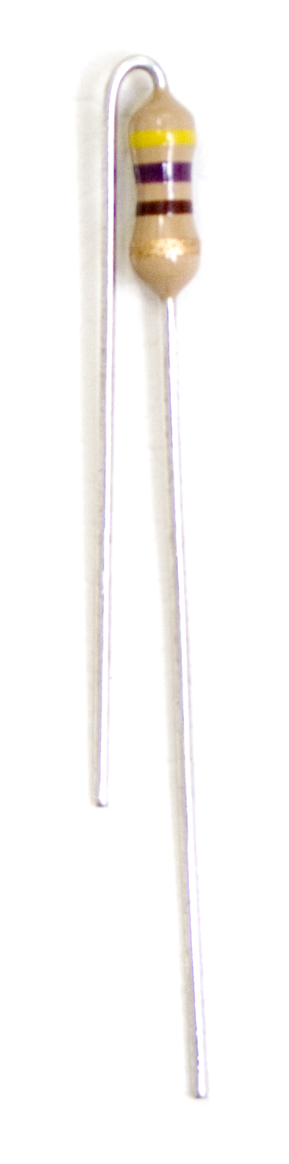
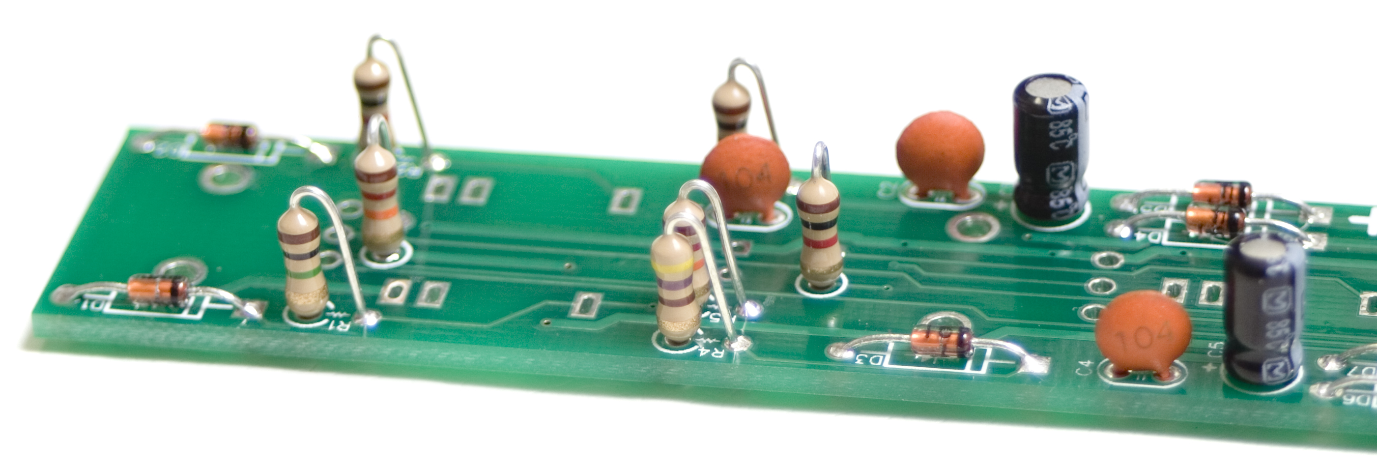
The resistors on this project are ‘stand up’ resistors, which means they need to be bent so that both legs are facing the same direction. Below is an example of how they need to look. It is important not to make the bend right next to the body of the resistor, as when they are soldered in, this can cause undue stress on the body and may lead to failure.
 Resistors are non polar, but it can make troubleshooting easier if you populate them in such a way that all the tolerance bands (usually a gold stripe) are facing the same direction. This will make reading the color bands a lot easier. When you have them populated as per the BOM, carefully flip your project over and solder everything in place. Then clip the excess leads. A tip to get these guys sitting flat is to solder the longer leg of the two on all the resistors, and then go back and reflow each one while gently pushing on the top part of the resistor to sit it flat.
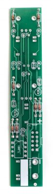
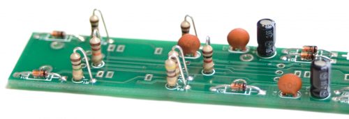
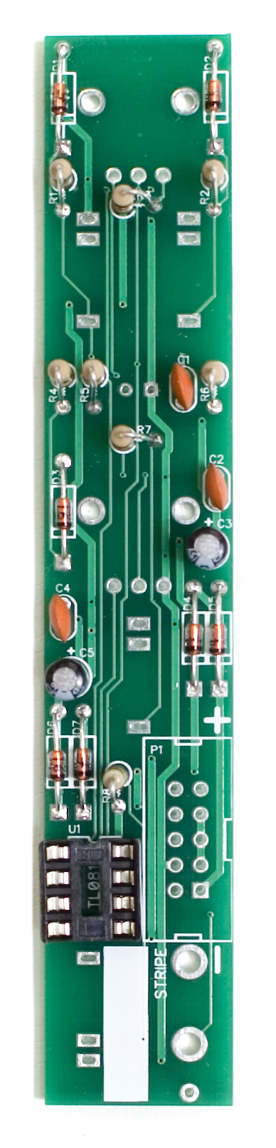 Below is a close up of how they should look after soldering.
 10 Pin Shrouded Power Header
Now we can populate the keyed power header. When populating, it is VERY important to align the side of the header with the notch with the same indication on the PCB. If this gets soldered backwards, it will break your module. When soldering this in place, you can use the same trick as on the IC socket, with only soldering one pin, then coming back and making sure its flat and then soldering the rest of the pins.
 Front Panel Components
We are now going to start populating the front panel components. Do NOT solder anything yet!
The order in which you populate the components doesn’t matter, but make sure when populating the LED that you align the longer leg AWAY from the flat side indicated on the PCB, as shown below.
Next, carefully populate the rest of the components.
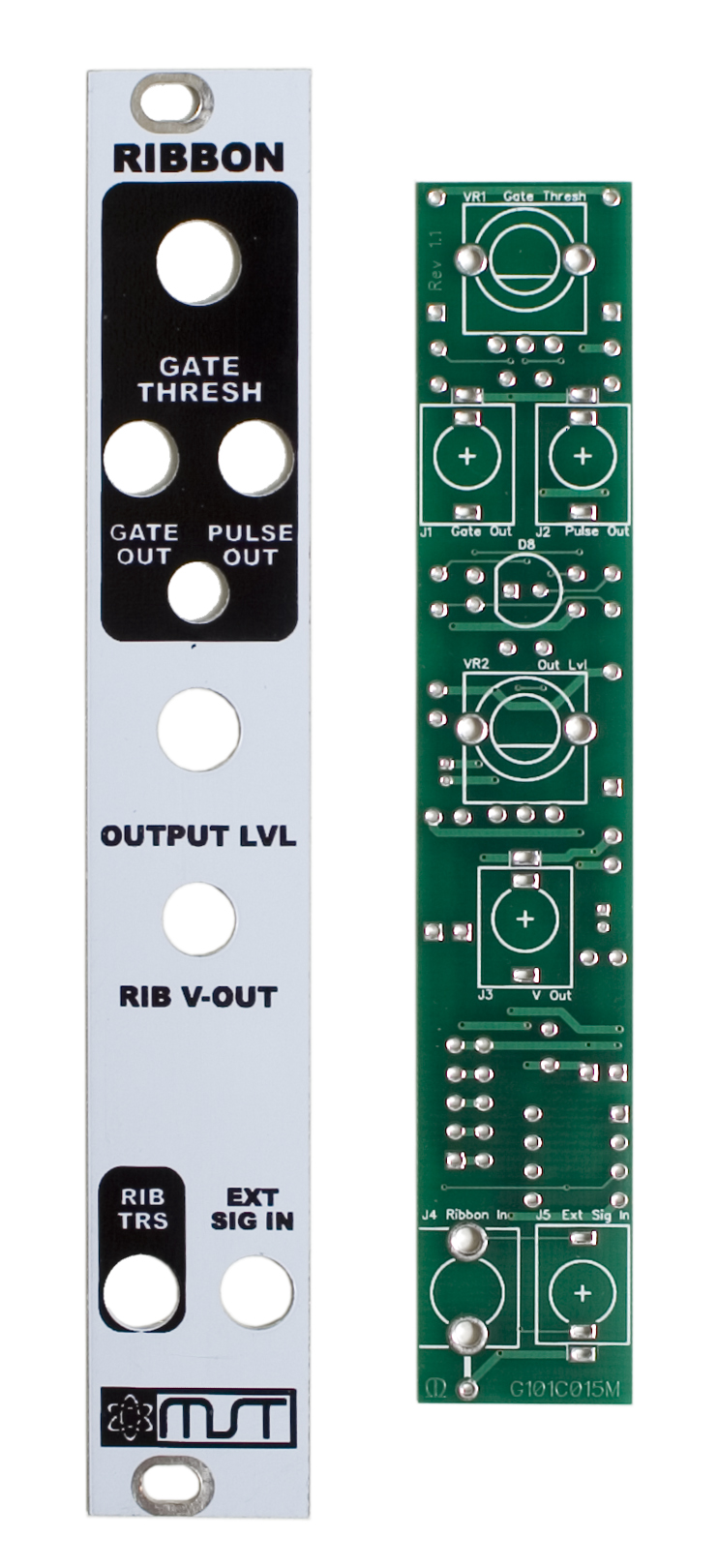
 Front Panel Placement

Next we will place the front panel over all of the components we just populated.
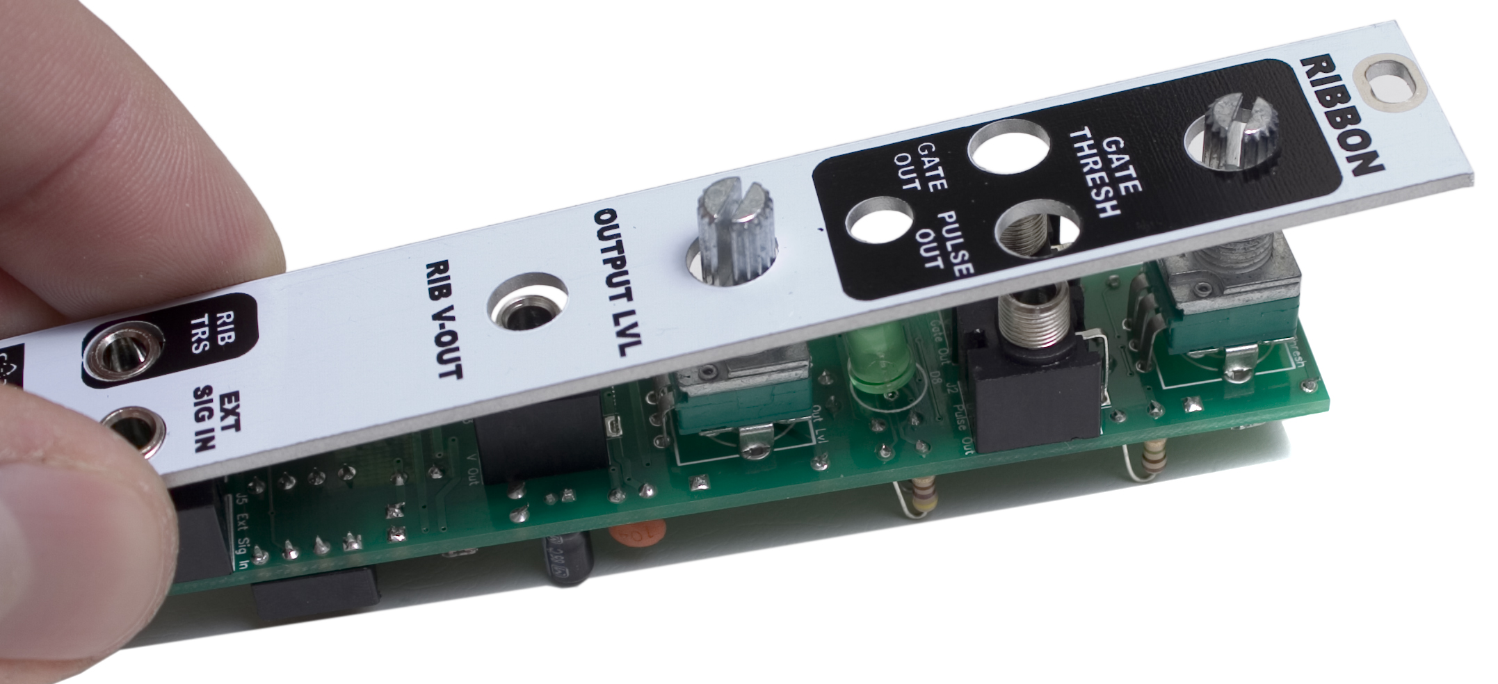
Then carefully thread the nuts onto the components by hand, and come back with a tool to tighten them. Be careful not to over tighten!
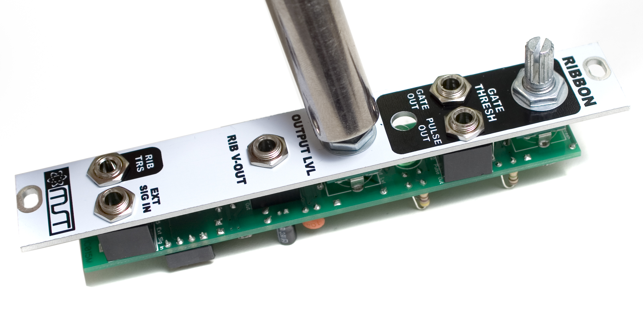 Next, take a close look at all of the components, and make sure they are sitting flush with the PCB and that they are straight. Once you are happy with the placement, carefully flip your project over and solder everything into place.
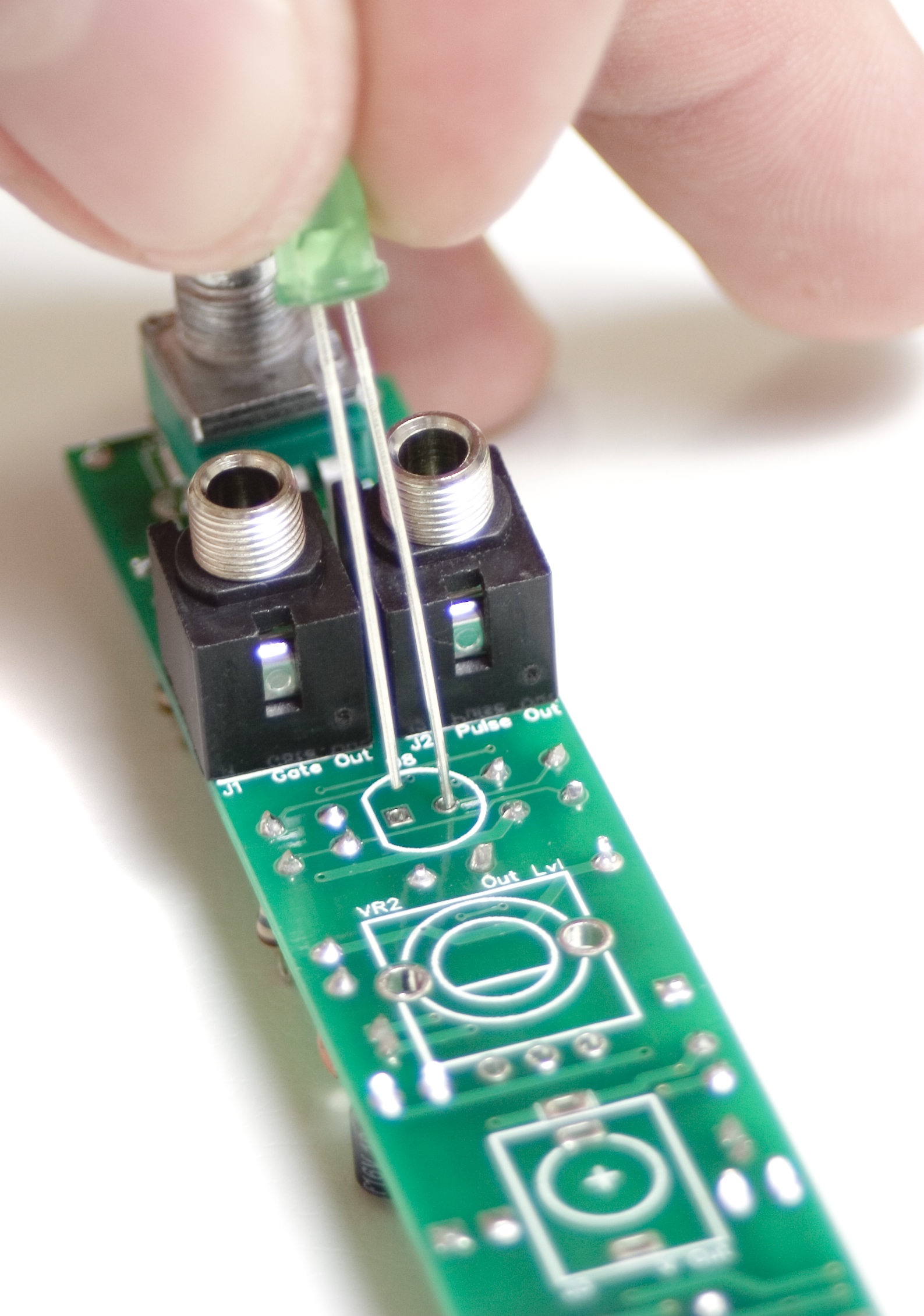
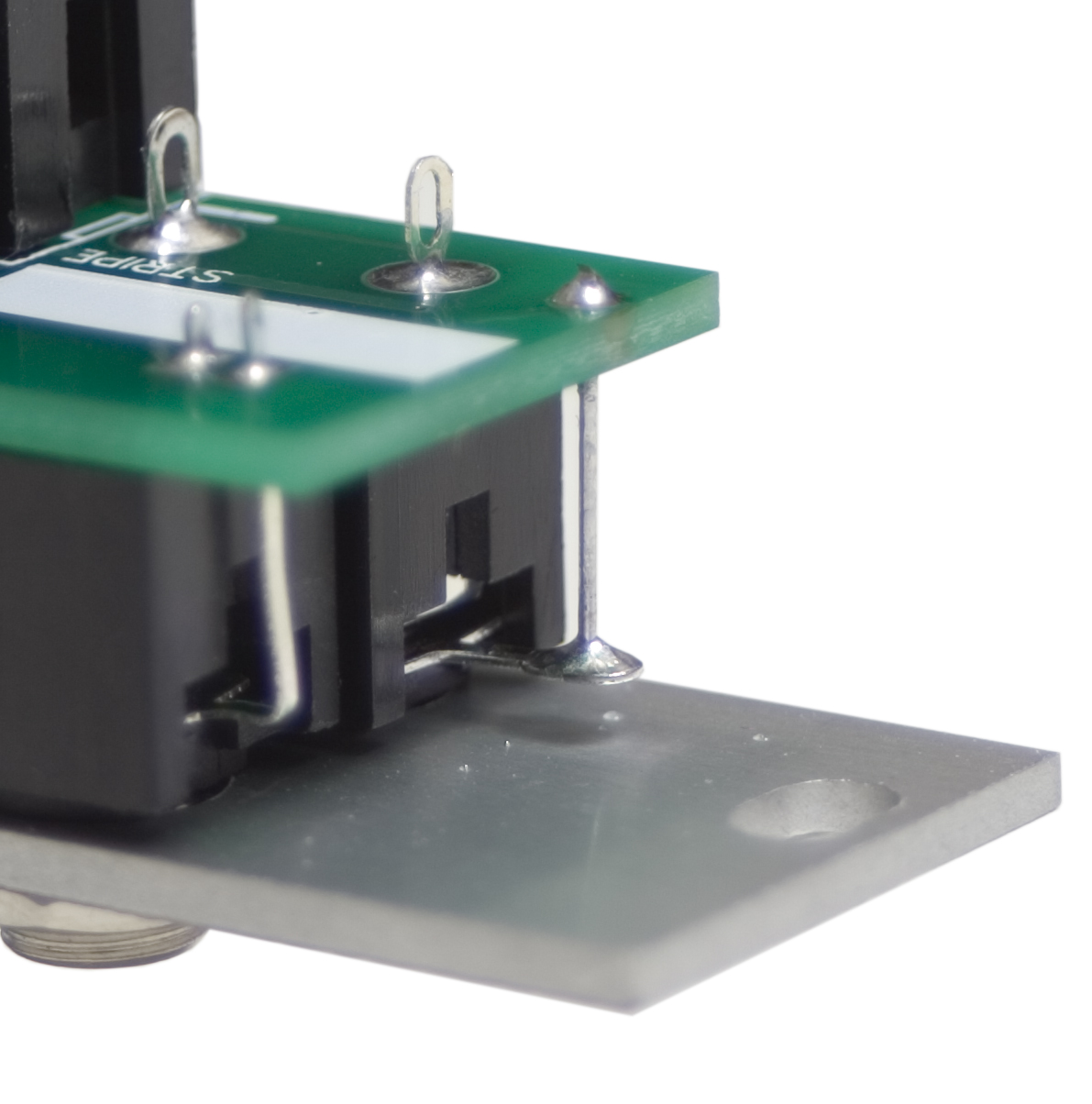
Stereo Jack Ground Lead
Now we are going to use that resistor or diode clipping from earlier. Using a set of pliers or tweezers, carefully insert the diode clipping through the PCB and make sure that it goes through the ring in the jack’s leg, as shown below.
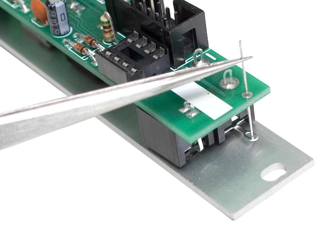 Once you are happy with the diode clippings placement, solder it into place, and clip the excess that is hanging off the board.
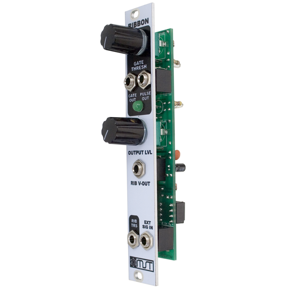
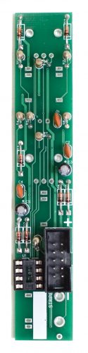
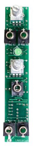
 Completed Module
Congratulations! You just completed building the MST Ribbon Controller Module!