


Important Links
Product Page
Bill of Materials
Capacitor and Resistor Lookup Guide
NEW 8 Step Sequencer Assembly Instructions
Welcome to the NEW 8 Step Sequencer Assembly Instructions! If you’re new to circuit-building, this is a big kit and it takes some work so go slow and pay close attention to details. It will be well worth your time! Let’s get started!
BOM Layout

If you received your kit and you’re ready to build, the first step is to check to see if you have all of the parts. Above is the picture of the 8 Step Complete Kit. Check your kit against the BOM. If you’re missing anything, we’ll send it to you free of charge.
Below are pictures of the other bare bone kits you could have ordered
Bare Bones Kit w/ Hardware

Bare Bones Kit w/ Soft Components

Basic Bare Bones Kit

PCB Components

Line up the half-moon notch on the IC sockets with the notch drawn on the PC board.
Capacitors and Resistors

The next part of our build are the capacitors. C2, C3, C5 – C10, and C12 – C14 are .1uF non-polar ceramic capacitors, so their leads can go in either through-hole their silkscreen designates. They look similar, but they have different values that are printed on their body in small lettering. They are labeled ‘104’.
C1, C4, C11, and C15 are 10μF polarized electrolytic capacitors. These capacitors must be placed correctly for the circuit to function correctly. Most electrolytic capacitors have a thin band on their body (grey in the picture above) that denotes the negative lead. New electrolytic capacitors will also have a longer positive lead.
LED/Diodes

Make sure the longer lead goes into the circle through-hole which is positive and the shorter lead into the square (negative) through-hole.
If your going to put your complete sequencer in a case you will want to wire the LED.

The small signal diodes will be used for D9 – D16, and D18 – D21. The Zener diode will be used for D22. Match up the black (negative) band on the diode with the white band on the PCB.
Transistor

Align the flat side of the transistor with the white flat line on the PCB
Wired Components
Potentiometers


Our first wired components to add to the PCB are Pot1, POT2 and POT3.

Match the PCB through-holes to the potentiometer solder lug numbering above. Solder wires to the potentiometers, then insert them into their corresponding position.
When installing the pot, some pots come with nubs near the shaft that may get in the way of installing the circuit into a case. Check for a nub and clip as necessary.

Don’t forget to cut the nubs on the potentiometers as neccesary.
Power Connections/Jacks

Connecting the 9V battery adapter jack is easy, so we’ll do this first. The red wire is connected to the square through-hole next to the ‘+’ silkscreen. The black wire is connected to the circle through-hole next to the ‘-‘.
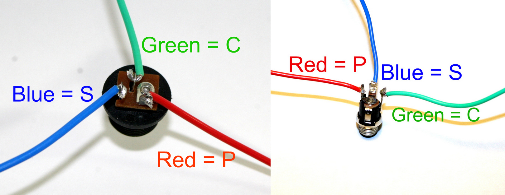
DC Jack Pinout
The DC Jack is fairly straightforward. Connect three wires to the DC Jack’s solder terminals and, using the picture above as a reference, connect them to the PCB at their respective through-holes.
If you do not want to install the 9V DC jack and only install the 9V battery clip you will have to short the S and C pins for the 9V DC Jack like shown in the picture below*.
* Your PCB may not look exactly like the photo, that is ok. What is important is that you short the same pins as shown in the photo.
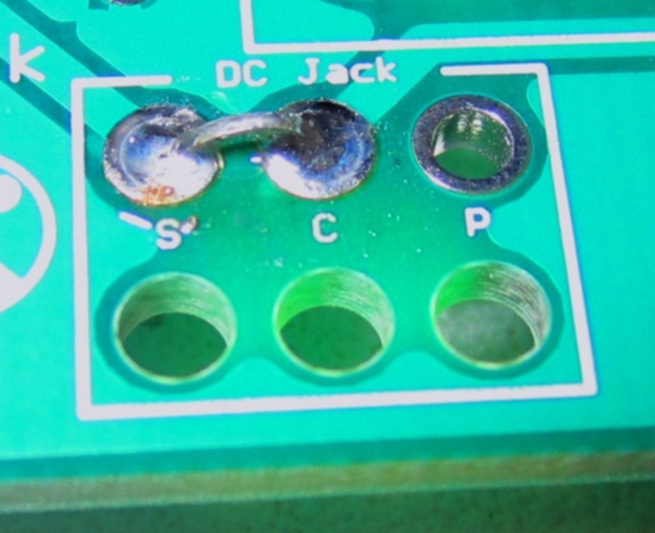
Short these contacts to get the circuit to work without the 9V DC Jack
Mono Jacks


The APC needs three mono jacks for the ‘CV-IN’ and ‘OUT’. There are two solder lugs on 1/4″ mono jacks, with the ‘S’ standing for Sleeve and ‘T’ standing for Tip. On the PCB, locate the through-holes for ‘CV-IN’ and ‘OUT’ Both of these have a ‘T’ and an ‘S’ next to the through-holes. Using the picture above, connect the mono jacks to the PCB.
SPST On/Off Switch


Wire the power switch as shown in the picture.
Steps

There are 8 steps that contain 4 components each. Lots of wires!!! Above is a picture to help simplify things. Step 6 has been color coded to show which parts go where. Red = 1/8″ Mono Jack, Yellow = SPST switch, Pink = LED, Blue = 10k Potentiometer
Use the images below for wiring purposes
Mono Jacks = Red

S = Sleeve, T = Tip
Switches = Yellow

The basic function of the SPST switch is to connect and disconnect the circuit. It doesn’t matter which hole the wires are placed in as long as they are in the yellow holes.
LED’s = Pink

Make sure the longer lead goes into the circle through-hole which is positive and the shorter lead into the square (negative) through-hole.
10k Potentiometers = Blue
Match the PCB through-holes to the potentiometer solder lug numbering above. Solder wires to the potentiometers, then insert them into their corresponding position.
Congrats!

That’s the end of the assembly! Put a battery into the 9v battery adapter jack, connect an external synth and an amplifier, turn the circuit on, and turn it up! Your main power LED should light up, and you should have a sequence coming out of your amp. If it doesn’t work, go back through the instructions and carefully check all of your work.
Have fun with your new hand-made 8 Step Sequencer!!
Hi,
good instructions of the build and by the way a very understandable PCB!
I’ve got a question: is it possible to modify the sequencer with a Slew/Portamento function?
When selected, each step should blend (or glide) into the other, unlike the typical square stepping. It should of course be switchable and with a pot for a glide speed.
Is this possible and how?
Thanks,
Alex
HI Alex, we dont have a mod for this yet, something we could certainly be working on. If you have any thoughts please let us know.
Thanks
I have a couple of problems. Potentiometers on bill of materials are not specified log or lin (a or b) They also are not consistent with the assembly instructions. BOM states: 10k, 1M and !k. Instructions are showing values of 100k, 200k. Maybe i am missing something.
I also don’t know how to use analog step sequencers. I have some eurorack synth modules but have always used midi to cv.
What is the function of the mono jacks per channel. What is the point of s cv out? I usually use 1 Cv for pitch and then control other parameters with a different set of cv steps. Would i use 3 cv for three oscillators and then a second step sequencer for fil etc?
I will check on the BOM and instructions, sorry for the late response. The Mono Jacks per step are used for reset, where you would patch a 1/8″ cable between the master reset and the step where you want the sequence to end. For example, you can have a 3 step sequence if you patch the master reset to the 4th step. The CV outs would be best used for 3 different oscillators (or other things), you could use the clock out to keep something in sync. But there is no gate on the 8 step, so you would have use something else for that, or out 16 step sequencer, which is more robust.
Thanks
I would like to build this but have the same confusion about the pots as William in the post above. I am seeing the instructions listing pot 1 as A100K and pots 2 and 3 as B500k, and the BOM listing is 1K and 1M. It would be great if this could be clarified for us.
Thanks!
Bruce
Another question, Steve…is the 4017 CMOS a quad or hex?
Thanks,
Bruce
Both?
Hex D-Type Flip-Flop Quad D-Type Flip-Flop
@Alex
Since there is no gate function on this sequencer, I dont think this is doable without some mod that would add a gate and a gate length. Our 16 step has this function. Sorry for no help for now
Sorry for the delay Bruce, we changed the BOM after the instructions were made, I fixed that, please follow the BOM = 1K and 1M. Better speed adjustment. Thanks!