


The PCB for this product has been discontinued.
Important Links
Product Page
Bill of Materials
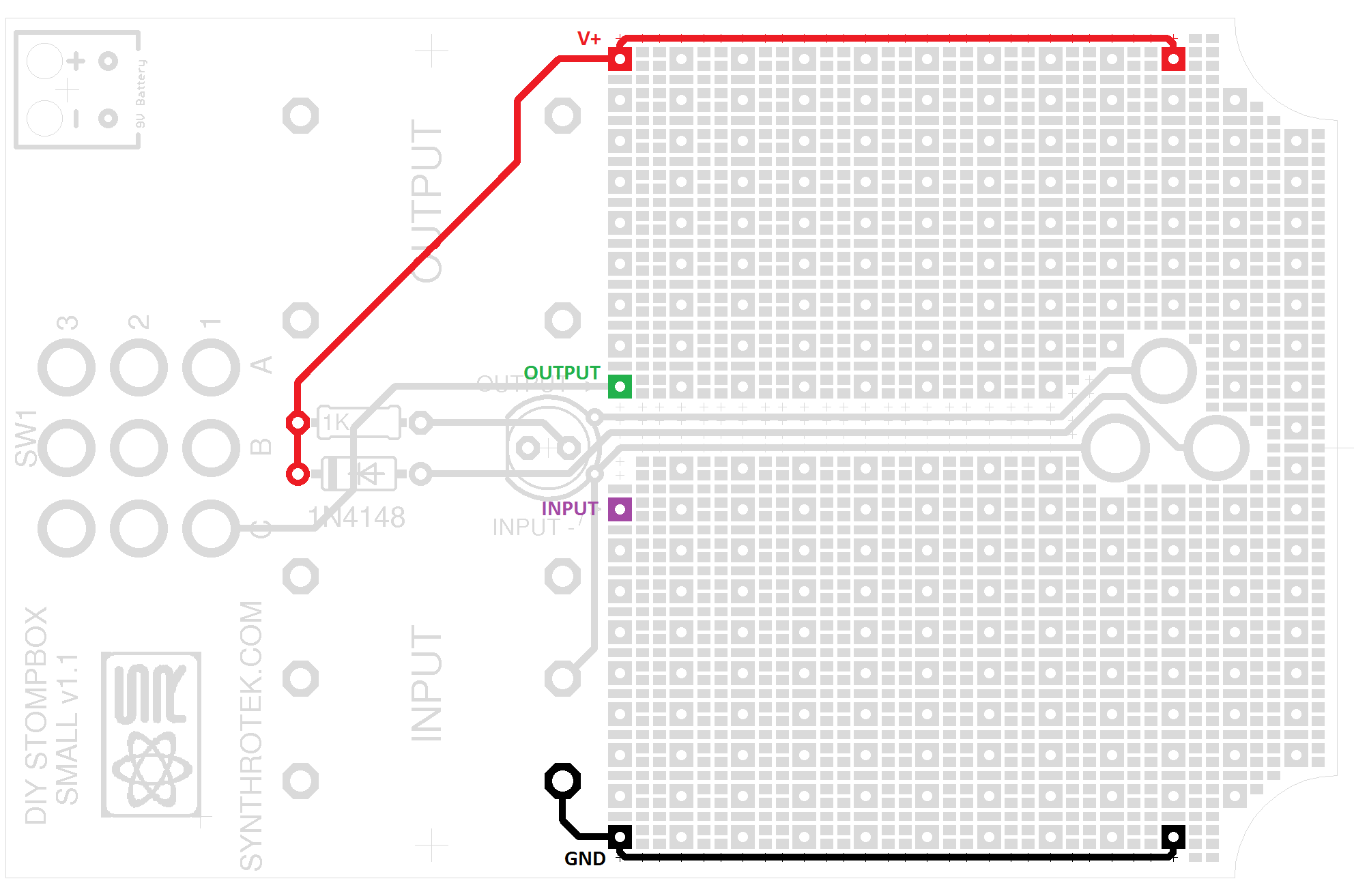
Layout Template
Schematic
Boost Demo Project
Capacitor and Resistor Lookup Guide
A small sanity check, are you really here for instructions on how to assemble the DIY Stompbox? If so, this kit is probably not for you! The DIY Stompbox is a development and prototyping kit. This kit is designed for people comfortable with electronics modding, hacking, bending, or whatever term you want to use.
Use of the DIY Stompbox:
The DIY Stompbox is a skeleton or foundation for your pedal ideas. The PCB for the DIY Stompbox has the typical center negative DC jack. The pedal is setup with a true bypass and an LED indicator for when the pedal is engaged. The DC jack is set so when a DC adapter is plugged in the 9v battery connector is disconnected from the circuit conserving battery life. The PCB is shaped to fit the Hammond style 1590B case and has ample area for building your own circuit.
The schematic for the DIY Stompbox shows how all the above features are wired and we’ve provided solder points for the input, output, V+ and gnd of your circuit. The solder points are marked in the DIY Stompbox template which we suggest using to facilitate building your project.
In assembling your project using the DIY Stompbox we suggest the following steps:
1) Plan your layout using the DIY Stompbox Template
2) Solder the components for your project in the project area starting with the shortest or least high components first, typically resistors and diodes and working your way to the tallest or any off board components. You may also want to solder the DIY Stompboxes LED resistor and reverse polarity diode when soldering the resistors for your project (easier this way).
3) Solder the DIY Stompbox components to the PCB.
4) Test, troubleshoot and do a victory dance!
If you have questions about the use of the DIY Stompbox don’t hesitate to email us. We’re probably not the best people to ask about your circuit since we will be unfamiliar with it.