Welcome to the Mega Drone Synth build instructions. The circuit construction is fairly straightforward, but it will require some patience when we get to the wired components (there are a lot of them)! Let’s get started!
BOM Layout
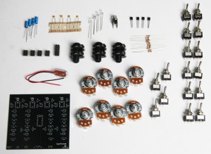
Before beginning any circuit-building project, always ensure that you have all of the parts required to complete the circuit. Check your kit parts against the Mega Drone Synth BOM.
If you are missing any components, we will send them to you free of charge.
PCB components
Let’s start with all of the components that are soldered directly to the PCB.
ICs and Resistors
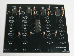
Insert the 4 555 timer ICs and the 4093 IC into the PCB. The IC half-circle notches should all point to the top of the PCB. If the ICs do not fit, gently squeeze the leads inward. The 12 1kΩ resistors are also placed onto the PCB at this stage. Solder all of the components onto the PCB.
Capacitors
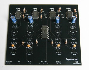
The next step is to add the capacitors. C1-C4 are polar electrolytic capacitors and require proper placement for the circuit to function. Note the black band on the body of the capacitors. The lead closest to this band is the negative lead and should . Insert this lead into the circle through-hole and insert the other lead into the square through-hole with a ‘+’ symbol underneath.
C5-C8 are non-polar ceramic capacitors and they can be placed onto the PCB without worrying about which lead goes into which hole.
LEDs and Transistors
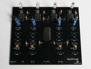
The LEDs D1-D4 are polar components and need to be placed properly. Look closely at the body of the LED – the flat edge identifies the negative lead. The negative lead will also be shorter than the positive lead. Just like the electrolytic capacitors, the negative lead will be placed into the circle through-hole and the positive lead will be placed into the square through-hole. If you are going to put your circuit into a case, you should use wires to extend the LEDs from the PCB.
The transistors Q1-Q4 are marked with a silkscreen circle shape with a flat side. Look at your transistors and notice how the body shape is similar – they will be inserted with the flat side facing to the right. Spread the leads out gently to fit them onto the PCB.
That’s the end of the first part of our build. The rest of the components will be attached to the PCB with wire.
Wired Components
Potentiometers
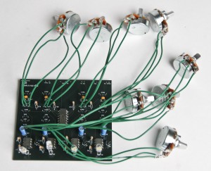
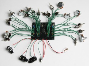
Our first components to be added to our circuit are the potentiometers. Note that your kit has two different valued pots – POT1-POT4 are 50kΩB and POT5-POT8 are 1MΩB. Make sure that you use the right pots!
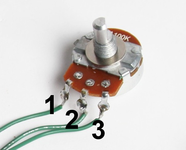
Look on your PCB and notice how the silkscreen has a ‘1’ and ‘3’ outside the rectangle for each pot. These identify which wires from the potentiometer go where (see picture above).
I suggest soldering wires to your potentiometer before adding them to your PCB.
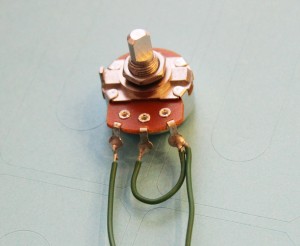
For POT5-POT8, the wiring is different from the other pots. You will have to connect solder terminals 2 and 3 with wire (as shown in the picture above) or by making a solder bridge on the bottom of the PCB. Solder bridges are prone to having connection issues, so we recommend using the wiring method. Connect the wires running from solder terminals 1 and 3 to the designated positions on the PCB.
Switches
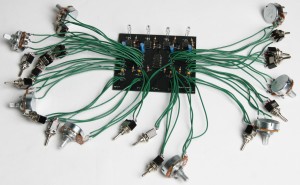
The next wired components to be added are the switches. There are 16 switches, so this step will require quite a bit of time. S1-S4 & SW9-SW16 are SPDT switches (3 solder lugs) and SW5-SW8 are SPST switches (two lugs).
Just like the potentiometers, the switch silkscreens are numbered on the PCB. When inserting the SPDT switches, make sure that the wire running from the middle solder lug is inserted into the middle hole. The other leads can be inserted into the remaining holes without worry about placement.
The SPST switches are just on/off switches, so their PCB placement does not matter. Make sure that the same solder lug on all the switches goes to the same numbered hole. This will make mounting the circuit into a case much easier, as all the switches can be oriented the same direction.
Solder wires to the switch solder lugs before you place them on the PCB. You might find it easier to work with an assembly-line flow when you do this step. There’s a lot of repetition!
Jacks
The last step is inserting all of the jacks onto the PCB.
The first set of jacks are the 3 1/4″ jacks (Clock In, Out, and CV In). Solder wires to the 1/4″ jacks before attaching them to the PCB. In the picture, the red wires are tip connections and the green wires are the sleeve connections. Tip connection wires go to the square through-holes and the sleeve connection wires go to the circle through-holes.
The 9V battery jack’s red wire is connected to the PCB at the circle through-hole and the black wire is inserted into the square through-hole.
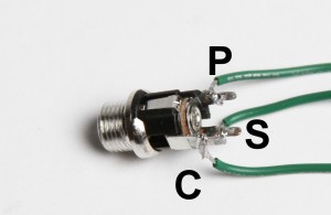
There are three solder connections for the DC Jack, center pin (‘P’), sleeve (‘S’), and connect (‘C’). On the PCB, note the square and two circle through-holes – the square is for the center pin connection, the middle circle is for the connect connection, and the rightmost circle through-hole is for the sleeve connection. See the picture above for solder connection identification for more detail.
Congratulations, you’re done building your Drone Synth! Now make sure it works! Put a battery in your circuit, put a 1/4″ plug into the ‘Out’ Jack and an amplifier, and see if the LEDs light up and the circuit produces some noise. If nothing happens, don’t panic! You may need to flip the switches and manipulate the potentiometers to get the circuit to circuit work at first. Do this for all of the rows of switches before doing anything else. If this does not fix your problem, double-check your power connections. If this still does not fix it, go back through the circuit and ensure that everything is inserted and soldered correctly.
Thanks for following these instructions. If you have any questions about the assembly, feel free to shoot us an email; we’ll update the assembly instructions to make it easier to understand. Have fun making some crazy noise with your hand-made 4093 Drone Synth!


I was looking at the 4093 Drone Synth – and there is no mention of it in your store. Has it been discontinued? Is it available as a kit? How much for the full kit? Thanks for any information you can supply.
Regards,
Ted Neil
Hi Ted, we have discontinued that project, but are working on a better version. Thank you for the interest
The SPDT switches are On-On type or ON-OFF-ON? or any other? would be nice to know what all the switch&potentiometer does. Thanks
They are On-On switches. Unfortunately we don’t have information on-hand about the functions of the switches and pots. It’s been a long time since we last had the Drone Synth in stock.
We are working on revamping the Drone synth though, but no ETA on that.
Hi again! So I’ve built it and it doesn’t work for my disappointment.
The LEDs light up but I don’t have any signal at output. Rechecked all the soldering, cables, replaced all the NE555, CD4093…. And nothing! I’ve built much more complex circuits before and debug some errors was more fast and pleasant. Are you sure there isn’t some bugs on this board?! Never seen a video of it working. I’ve also checked with a multimeter the voltages on each IC and they seem normal to me. The only thing different on my project it’s the DC connector that only have 2 pins. Also the 555 chips get really hot after 1 minute.. Help me please, spent a few bucks on this and I’m loosing my mind.
Any info you can give I will appreciate.
Best regards,
Leandro
When I toogle some switches they seem to work the right way,turn OSC off, modulate each other. LEDs blinking at some speed interval like an LFO but pots don’t do anything and no sound
Hey Leandro. Sorry for the issues. I would have to look some photos of your build before I can be certain. But I would start with looking at how you wired up the DC jack. Are you using a 9V battery?
The audio and DC jacks should be checked first. There is not an error on the PCB, as we have built up quite a few of these in the past. Video of operation from a while back can be found here: http://www.youtube.com/watch?v=5wfGbmW0lOA
Well don’t know what happen, something weird. Plugged it in later after taking a good nap and it works 🙂 but each time i move a switch seems to make a noise and overall volume is low even thru a good pre amp.
I’ve all the correct components, at first used some tantalum for the ceramic capacitors but since they have polarity i removed them and changed to the ones listed in BOM.
Would love to sort this out before putting it into a nicely made wood case. I’ll take some pics.
Any thing I may have fried? Have changed all IC’s and still the same.
Any mods I can do? And can you please try to tell me what each knob/sw does? I know, already asked before but would love to put some labels on the front panel.
Thank you Steve.
Hi guys, I would like to know where i could purchase all the needed components for building a drone.
I would prefer everything in one box, almost like a building kit that come with a assembly diagram etc. i have some knowledge with logic systems… but I am still studying. ill soon have my degree in megatronics… so Ill be very grateful if some one can point me in the right direction.
Kind regards
R.L.
Hey Ruan,
Since this is a discontinued product, we haven’t kept up on this build. We managed to scrounge up a PCB here at the shop but we can’t guarantee the PCB works or that the BOM is up to date, but if you’re interested in us selling you the one board we found, send us over an email at store@synthrotek.com
Good luck!
-Zach