


This product has been discontinued.
Important Links
Product Page
Store Page
Bill of Materials
Capacitor and Resistor Lookup Guide
Welcome to the assembly instructions for our short-run of Modular PT2399 Delay. This build is a limited run because the PCB was designed with the incorrect sized potentiometers, a style of potentiometers that have 16mm shafts, but it is completely functional and sounds great! This kit does not come with a panel.
You can get the kit with a 16-pin header for Eurorack power or a 4-pin molex adapter for Fractional Rack power.
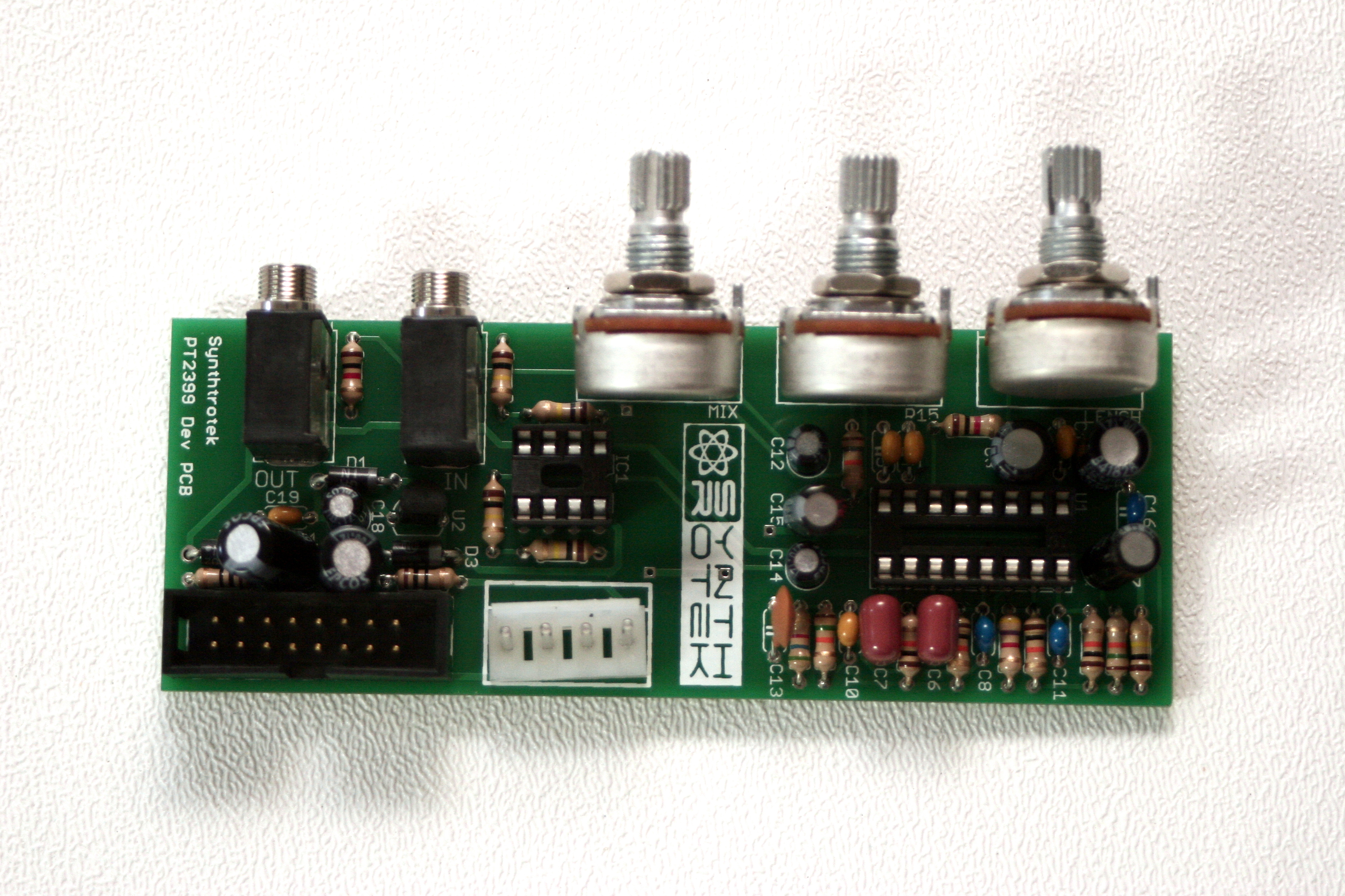
BOM Layout
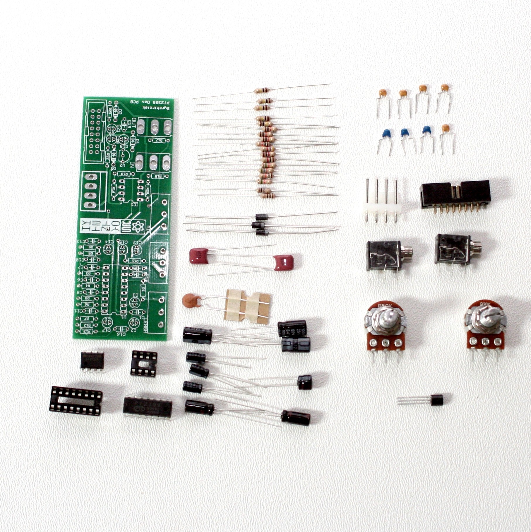
Modular PT2399 Delay for 16mm pots parts
If you’ve received your parts and ready to build, the first thing you should do is to check to make sure you have all the parts. Check your kit against the Modular PT2399 Delay (16mm) BOM. If you’re missing anything we’ll send it to you free of charge.
Soldering Components
Resistors and Diodes
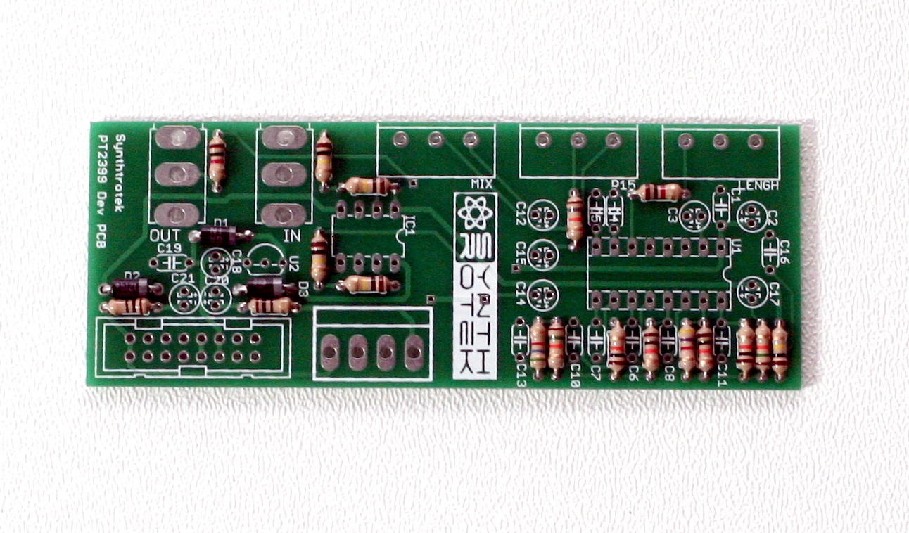
Modular PT2399 Delay (16mm) with Resistors and Diodes
First solder all the resistors and diodes into place. Ensure that the line on the diode matches with the line on the PCB silkscreen. Resistors are not polar sensitive so you may install them in any orientation.
Capacitors
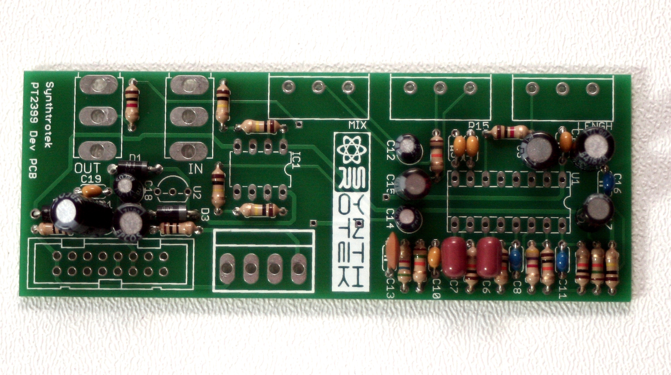
Modular PT2399 Delay (16mm) with Capacitors
Now solder all the capacitors. The electrolytic capacitors C2, C3, C12, C14, C15, C17, C18, C20, and C21 are polar sensitive. Make sure that the longest lead from the electrolytic capacitor goes into the hole marked with the plus (+) sign. C20 and C21 are located closer to each other than intended and you will likely not be able to have these two capacitors flush with the PCB. As long as the leads are not touching each other or anything else that is conductive other than the PCB itself you’ll be fine.
The ceramic capacitors are not polar sensitive and can be installed in any orientation.
IC Sockets and Voltage Regulator
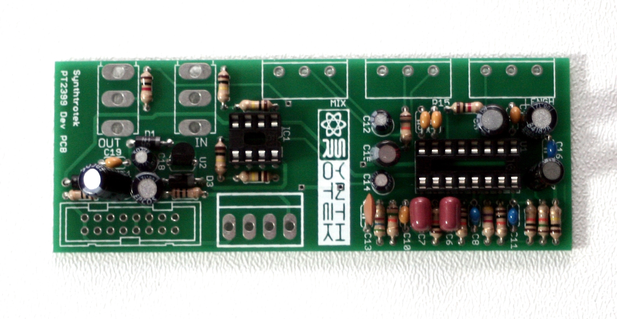
Modular PT2399 Delay (16mm) with IC Sockets and Voltage Regulator
Now lets install the voltage regulator and the IC socket. You need to align the flat side of the voltage regulator to the image of the flat side on the PCB silkscreen. For the IC sockets, make sure that the notch on the sockets matches with the notch in the image on the PCB silkscreen.
A tip for soldering the IC socket flat to the PCB, first solder two opposite corners of the socket and then make sure that you get the socket flush to the PCB. Afterwards solder the rest of the pins and touch-up the two first pins as necessary.
Large Components: Jacks, Power Plugs, and Potentiometers
Modular PT2399 Delay (16mm) Jacks, Power Plugs, and Potentiometers.
We are almost done with soldering! Just got a few components left. These are all 3 or more pin components and can sometimes be hard to get flush with the PCB. You can use a similar trick as with the IC socket to make sure that the component is flush to the PCB, just solder a single center-pin or two pins on opposite sides first and make sure that the component gets flush to the PCB, and then solder the rest of the pins.
Lets take care of the power connector first. Depending on if you ordered the EuroRack version or the FracRack version you will only have one of the 16-pin shrouded header or the 4-pin molex but not both. Match the connector to the image on the silkscreen, ensuring that the notch on the 16-pin header is aligned with the image of the notch on the PCB, or ensuring that the 4-pin molex connector latching mechanism is aligned with the image on the PCB.
Now you can install the audio jacks and the potentiometers.
When installing the pot, some pots come with nubs near the shaft that may get in the way of installing the circuit into a case. Check for a nub and clip as necessary.

Don’t forget to cut the nubs on the potentiometers as neccesary.
Completed Circuit
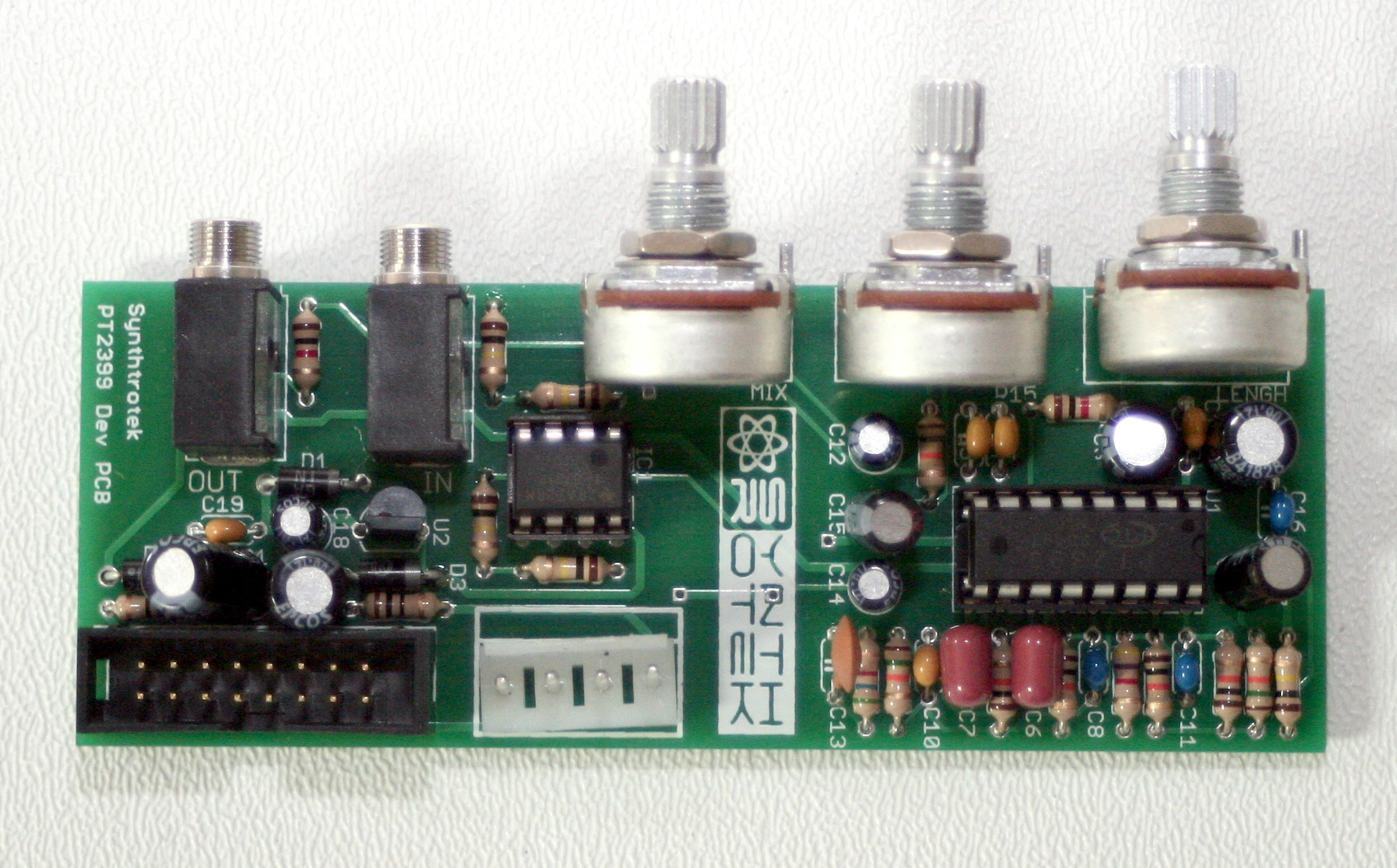
Modular PT2399 Delay (16mm) Completed
All you need to do now is insert the PT2399 and TL072IP ICs into their IC sockets, making sure that the notch on the IC matches the notch on the IC socket. Attach a panel, install into your Euro or Frac Rack and make some echos! Have fun! And we love to hear back from our customers about how they’re putting our products to use!
Is it possible to add switches and 1/8″ jacks with the pots to have cv access control points for the three variables on the board? The switches would allow either the pot or the jack to be in use for each of the parameters.
Hi,
It’s possible to get the end result of what you’re looking for, but it would involve more than just some switches and jacks. You would need to also include a component to translate the control voltage into a resistance. A vactrol would be good part for that job, but you would also have to modify the circuit further to ensure that the vactrols provide a similar resistance range as a potentiometer it is standing in for.
So, while it’s possible, it’s not easy and I wouldn’t suggest anyone that isn’t very familiar with electronics to attempt such a project.