


Important Links
Product Page
Store Page
Assembly Instructions
Bill of Materials
Schematic
Capacitor and Resistor Lookup Guide
The Synthrotek Passive Ring Modulator is one of our simplest circuits to build, but yields the biggest payoff. It’s great for a beginner’s first project or the experimental musician. Retro sci-fi weirdness, crazy modulation, and unlimited sounds are possibile with this project. One of the best features is that this circuit requires no battery power at all – everything is passive.
Parts Layout
Before you begin building your Passive Ring Modulator, make sure you have all the parts to complete your project.

Ring Modulator Kit
1x Ring Modulator PCB (Printed Circuit Board), 4x 1N34A germanium diodes, 3x mono audio jacks (1/8″ or 1/4″), 2x 42TM018 transformers, and wire; that’s it!
Let’s get started building!
PCB Components

Soldering diodes to the PC board
When soldering the diodes to the board line up the black (-) lines with the thick white lines on the PCB.

Transformers
Before inserting the transformers into the board, bend out the side mounting pins so they will be flush with the board.

P side S side
Also, each transformer has a P (Primary) side and a S (Secondary) side. The transformer will have a “P” marking or a red dot above pin 1; both of these indicate the primary side. Make sure to match the sides up properly with the indications on the board

Transformers on board
Nice! Now for the wired components!
Wired Components
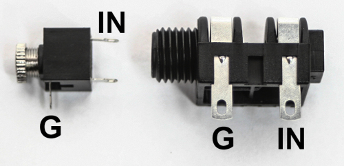
Choose your length of wire, strip it, then solder the wire to the Tip/IN and Sleeve/Ground of your jacks.

Wiring to the board
When soldering the wire from the jacks to the board, make sure it goes in the correct place! T is for Tip and S is for Sleeve Complete Ring Modulator If you are using 1/8″ jacks with your Passive Ring Modulator, here are some extra pics to help you hook it up right: 1/8″ Mono Jack The middle solder terminal is not used, so you can cut it off if you want. Complete Ring Modulator With 1/8″ Jacks
That’s it! Now go and make some crazy music!
I’m sure that I’m not the first person to try this. I ran my stereo guitar rig through this circuit as the input and carrier. The result with 20dB gain on both, and Fuzz on the input only was a step towards an Electroharmonix Octavia. It’s still really gnarly sounding but definitely something for me to experiment with. 🙂
Great little kit! Thank you!
Can it accept euro levels?
How many hp’s if I mount it on a euro panel?
Thanx!
Would it be practical to have attenuaters on the input signal and on the carrier’s input?
If so, 100k log pots?
Thanx!
Could it be mounted on a 1u 12hp?
Hey Jenz,
It’s .85mm too big to fit in the 1u row :/ I suppose you could dremel down one side a bit, though!
-Michael
That would definitely get you a bit more control of the experience! 100k log are what I’d give a whirl with to start. You can always fiddle about if the response is too little great for you 🙂
Michael
You bet it can handle them hot euro signals!
The Ring Mod board is about .2mm bigger than a 6hp panel.
Cheers,
Michael
Are the diodes in this kit matched?
Not emough space to put atts on my 12hp 1u panel.., No biggie, I got lots of attenuation in my rack.
Thanx for the answers Mike!!!
Hey Maarten,
The diodes in the kits are not matched. If you’re real interested in matching them, I’d buy a handful from the evilbay or your favorite place and follow Ken Stone’s process “To match diodes, try connecting them in series with a 10k resistor across 10 to 15 volts, and measuring for identical drops across the diodes themselves. It would be best to use the same supply and resistor for all measurements, and try to do all measurements at the same temperature. Avoid handling the diodes while testing them to prevent body heat changing their temperature.”
Thanks,
Michael
Apologies for the newbie question.
What is the third 1/4″ jack for (carrier)?
I just got everything wired up but didn’t use the third jack and I’m getting no sound when testing.
Thanks!
Hey Patrick,
Ring modulators work by taking TWO input signals, multiplying them, and outputting a new signal includes a sum and difference between them. If you’re only using one signal, then you won’t get crazy sounds. If you’re trying to use this with a guitar, I’d suggest putting together a simple oscillator such as our 555 timer to use with the signal.
Thanks,
Michael
Thanks so much Michael!
I am indeed trying to make a ring modulator pedal for guitar, and that helps immensely.
One question….if all is functioning, should I just hear the guitar signal unaffected? Or does it not work at all unless all 3 signals are present?
Cuz I get nothing at all signal-wise from the guitar…just silence.
Thanks again,
-patrick
Glad to help, Patrick!
If it’s fully functioning, you still won’t get an output without two inputs; so I wouldn’t be sweating about the absence of sound from just one input. You can test if the ring mod is working if you have another guitar or stereo outputting pedal to run both signals into the inputs. The effect won’t be as drastic as if you had two separate sound sources, but you will get an interesting new tone for sure. 🙂
Thanks,
Michael
Again thank you, Michael. When all you taught me sank in…I put the 3rd input on ring modulator and ran my iPad audio out into it. I fired up Animoog and learned exactly what you said. I strummed the guitar and then struck a note in Animoog and there it was.
So great.
Whoa!! That’s a rad way to test the little guy! Animoog definitely blows a little square oscillator out of the water. I bet you had some fun with that! I really appreciate you getting back to us and letting us know of your success and growth. Being there when folks have “aha!” moments with gear is one of the best parts of working here 🙂
Thanks,
Michael
Thanks Michael! This is fun and I appreciate your responsiveness and guidance. Kudos to you for such great customer relations.
I just bought the oscillator…looking forward to working that in.
Another question…I’d like to build a mix / blend pot into the pedal to dial up and down the ring modulator effect on the guitar signal. Do you guys have a kit for that sort of thing?
Cheers to you and thanks again.
-patrick
Mine works but has a massive drop in volume. I have rechecked all my solders and instructions. Could I have something backwards? Any suggestions? Thanks!
Hi Keven, the circuit is passive, so having a volume drop is normal. It needs a really hot signal in order to work.