


Important Links
Store Page
Product Page
Assembly Instructions
Bill of Materials
Capacitor & Resistor Lookup Guide
Schematic
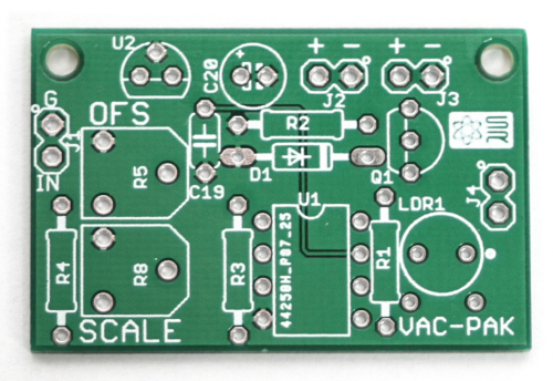
VAC PAK PCB
Congratulations on the purchase of your VAC PAK PCB or kit. This circuit allows you to convert your CONTROL VOLTAGE (MAX +10V, more may burn up your vactrol!) source and get variable resistance out! Set the scale and offset via two trim-pots and find your usable range somewhere between 750 ohms and up to 4M. This is a fairly easy build, but please make sure you follow the instructions in order to help ensure proper performance.
RESISTORS
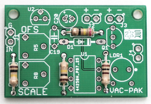
VAC PAK Resistors
First populate the 4 resistors as shown above, turn board over to solder, then clip leads.
SOCKET AND DIODE
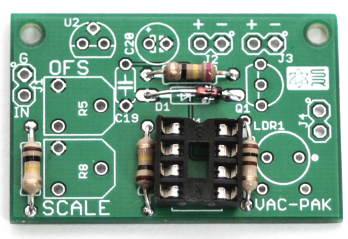
VAC PAK Socket and Diode
Next add the diode by aligning the black-striped end of the diode with the white-stripe end on the white silk-screen graphic. Now place the IC socket by aligning the notch in the top of the socket with the notch on the white silk-screen graphic. Turn the board over, solder and trim leads. You can now add your IC as well by aligning the notch on the IC with the notch on the socket.
Timmers, Vactrol, Caps, Voltage Regulator and Transistor
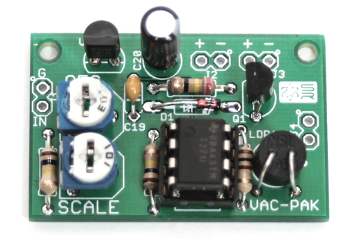
VAC PAK Trimmers, Vactrol, Caps, Voltage Regulator and Transistor
Add the ceramic capacitor; turn over, solder and trim. Now add the transistor and voltage regulator by aligning the flat sides with the flat side on the silk screen graphic. Turn over, solder and trim. Add the polarized electrolytic capacitor. Make sure that the long lead of the electrolytic capacitor is inserted into the hole that has the “+” marking next to it. Turn over, solder and trim. Now you can add the trimmers, as shown above. Turn over and solder.
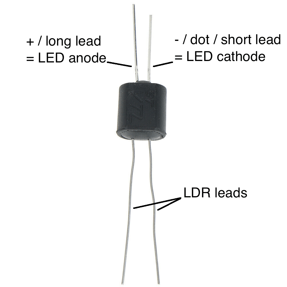
NSL-7053 Vactrol
Now add the Vactrol by aligning the white dot on the LED with the white dot on the PCB silk-screen graphic.
VTL5C3 Vactrol
There is a small “+” sign on the side of the vactrol that needs to be oriented on the OPPOSITE side of the dot on the PCB. Look for the red + in the picture below for the proper alignment.
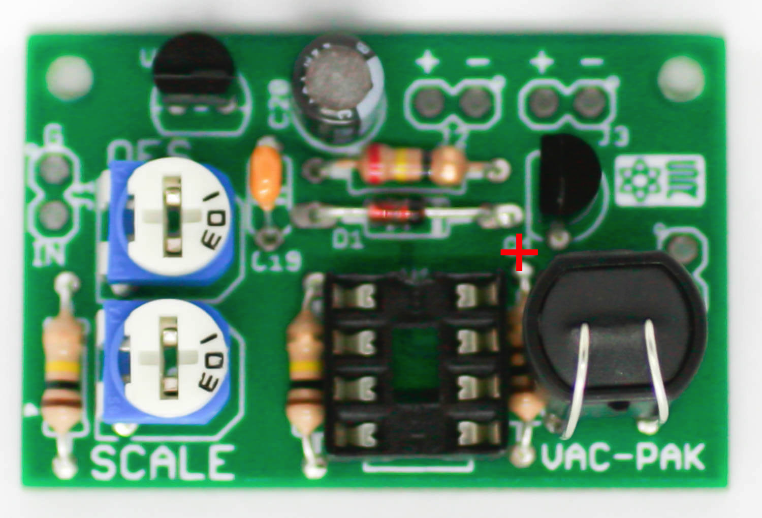
Align the + on the VTL5C3 with the red plus in the picture
WIRING AND JACKS
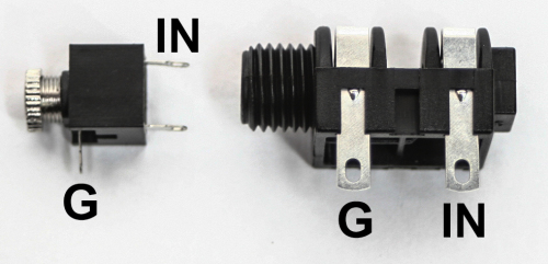
3.5mm & 1/4″ Jacks
Next we are going to wire up the project and we will start with the jacks. A 3.5mm (1/8″) jack OR a 1/4″ jack can be used. The jack takes in the Control Voltage. Cut and strip some of the wire to (desired length) included in your kit and solder one end of the wire to the connections shown above and solder the other end to the PCB at J1.
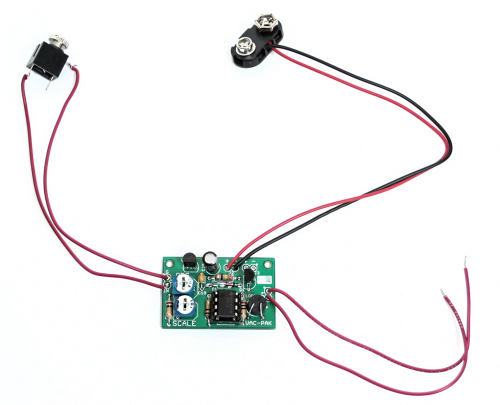
VAC PAK Complete
Now attach more wire as shown above. You can connect the 9V battery snap to either J2, or J3, or you can just connect J2 or J3 up to your project’s on-board voltage source. The other (either J2 OR J3) connector allows you to daisy chain multiple VAC PAKS to the same power source. The VAC PAK has an onboard 5V regulator, so this project can be powered with 6-18V DC. The wires connected to J4 work as a variable resistor! Connect these ends to a spot of resistance that you would like to now be variable resistance! The trimmers allow you to offset and scale the incoming voltage as to get a usable range that works for your circuit.
Enough! Lets get this into your circuit and start bending with CV power!
Hey guys – R1 & R2 seem to be reversed on the BOM vs the photo above…which one is correct?
Sorry for some Noob questions: I am lining up the white dot on the Vactrol with the PCB (i.e the long leads of the Vactrol are on top of the PCB and the short leads underneath), but I notice that if I do that the printing on the Vactrol is upside down compared to your photo…for it to be the same, the white dot on the Vactrol would be opposite the white dot of the PCB.
Which is correct?
No worries on the printing. Just match the dots up. Thanks!
@Danielo
The PHOTOS are correct and NOW the BOM and Visual BOM are both fixed. Thanks for catching that!
No problem – I suspected that the photo was correct from looking at the schematic…I have my high school electronics class to thank for that skill 🙂
Just got the kit. Both pots are 10K (103) in the kit and on the BOM, but the schematic says R8 should be 100R, which is reflected by your assembly photo above (101?)
The BOM is the most up-to-date parts list. We feel this works better in the circuit.
Hi!
Is it possible to use a TLC271CP instead of a TLV271IP? They are much easier to find for me…
Thanks.
Hi Gael, I’m not sure, I would suggest comparing the data sheets of the two ICs.
Looks pretty close… It seems that the TLV is a newer version…
Can I solder the two wires from the battery power input to any euro modules power pads? Thanx!
Jenz, that’s what I do and works fine. Voltage regulator takes care of the rest.
Gael, I use TLC271CP and works fine.