Important Links
Product Page
Store Page
Assembly Instructions
Bill of Materials
Schematic
Capacitor and Resistor Lookup Guide
Passive Ring Modulator
 |
 |
Features:
The Synthrotek Passive Ring Modulator PCB is the classic 2 transformer – 4 diode ring modulator circuit in a conveniently small package. Passive ring modulation is a bizarre and otherworldly sound effect appearing in such diverse places as sci-fi robot voices, trippy psychedelic guitar solos, metallic analog synth samples, and more! There’s nothing on this planet that sounds like ring modulation and now you can get it for cheap! Experiment with all of your gear and you’ll definitely come up with some surprising tones you never knew you had access to.
Operation: Two input signals are multiplied together and the resulting output is the sum and difference of the frequencies of each. The germanium diode ring provides the effect with a minimum of signal distortion while the transformers segregate your audio sources from the internal circuitry. The circuit requires no external power supply!
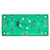
Measuring 2 9/16″ x 1 3/16″, the Synthrotek Passive Ring Modulator PCB is a compact, high quality circuit board. The PCB allows for the transformers and diodes to be soldered directly to the board neatly and a ground plane helps reduce interference from external noise and RF.
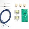
The Synthrotek Passive Ring Modulator Kit includes all of the components you’ll need to build your very own Ring Modulator. The build is a great beginner’s 1st project with a big payoff! Use it as a standalone unit or as a module, the Synthrotek Passive Ring Modulator is a great addition for your next synth project!


Is there any noticeable volume drop compared to the carrier? In other words, to implement this as something I could switch into an existing circuit, would I need to amplify the signal coming in or going out to maintain unity?
Hi Rick, since this is a passive circuit, all the amplification of the signals, in order to get the desired “mixture” of sounds, needs to happen prior to the Ring Modulator. There is not really a specific drop and both of the inputs are considered “carrier”. Although, and you can experiment here, both inputs and the “output” can all be used as in or outs. You can get some cool sounds!
Hi
Could this be used with guitar, say after a booster pedal?
Regards,
Nigel
This would work great with a guitar, of course you would need another signal, but it could be a simple waveform to another guitar, keyboard, really anything.
Got this as an impulse purchase with my EKO kit and it was totally worth it. Put some pierogies in the skillet, open up the package, and the whole thing was done before it was time to flip the pierogies. About as close to instant gratification as it gets.
Hey Synthrotek, I have been running Composite Video signals though the Passive RM. It works really well. With a few modifications. I’ll have to link it up on here when ive got it up somewhere.
Yeah, that would be awesome!
Hey Synthrotek, I have completed my Video – Sound modulator. But upon casing it up i get a very muddy non good signal. Is it to do with the ground being shared on all inputs? Do i need to isolate each individual ground. The case is metal so in the mounted state, all Input/Outputs of the RM are shared on the ground side. Any advice much appreciated. I don’t really want to use shoulder spacers. They wear really quickly. Thanks
Hi! About the audio trnasformers, i cant find any around where i live, could i use another kind of transformer? 1:1 x:1 1:x ? Nice sounds you got there !
Hey Eli,
Our transformers are 1:1.
So you should be all good!
Here is the datasheet:
http://www.mouser.com/ds/2/449/XC-600134-205894.pdf
-Zach
will this run off of 6 volts? i’d like to wire it into a circuit bent casio and run it off the 6AA batteries and combine the casio and either my atari punk console or use a 555. in that regard will the apc run off 6 volts as well?
The passive ring mod is passive so you don’t have to worry about that since it doesn’t require power.
The atari punk and 555 timer should work off 6V but the range of oscillators may slightly change.
Hey Synthrotek, I built this kit yesterday and I love the super gnarly sounds. I have 2 questions (super huge DIY / circuitry noob here):
1. I have noticed that when I have something plugged into both inputs but only one of the inputs is receiving a signal, I hear that un-modulated signal, although at a much lower volume than the modulated output of signals going into both inputs. Is this normal? Or is the output supposed to remain silent until another signal is introduced and they are mixed together? Like I said I am a soldering noob and I have noticed that although everything is soldered in the right place and none of the solder is touching anything it shouldn’t be touching, just want to make sure this is normal and not due to my own error.
2. I want to experiment with running very loud feedback loops from a mixer into the passive ring mod through the auxiliary channel of my mixer. Is this unwise? Could this damage the ring mod circuit?
Hey Ramon,
That is normal if its a slight amount of bleed. Its a passive circuit which is part of it. If you wanted to email me a video/audio recording of the bleed your experiencing to synthroteksales@gmail.com I can tell you if its normal compared to a perfectly operating one.
2. I’m not exactly sure how your doing it, but that shouldn’t damage the ring mod. I’ve done a lot of stuff with mixer feedback over the years, and while you should be really careful with volume, I haven’t actually ruined anything yet besides some speakers and my hearing 🙂
I built mine with “lifted” ground for in and out. (I bent the transformer pins for the “Sleeve” connection away from the pcb, and soldered the jack directly to it.) I did this only because I’ve seen schematics where ground was not shared, and the idea of transformer isolated signals appealed to me. Not sure if it changed anything material in how this circuit works.
But I’m VERY impressed with the sound and the flexibility of this module. I have a “4 quadrant multiplier” based ring modulator that only likes very hot signals. This one however seemed to perform just fine even with line level signals, provided the signals were reasonably close to each other in amplitude.
One tip for people – play around with which signals you send to In and Carrier. Sometimes, using your most complex signal as the carrier gets cooler sounding results. Also, drum machines seem to love ring modulators, as of course do vocal samples.
Hi there Synthrotek,
so here is my idea. I would like to build the passive ring mod and follow your guide on how to made it active with the 555 but use your 4093 chaos nand handheld instead. Is there anything else i would have to do in order to make this work?
Hi Manny! This is really all you need
Great! just ordered the two kits. One last question: in the mod guide, it reads that i should connect the output of my oscilator to the ‘ring’ on carrier y. this is confusing to me since i thought the input was a mono jack with only tip and sleeve. am i missing something here?
Hi Manny, yes, that should be Tip, looks like our error
Hi, I just built mine, and it has an intense humming issue. Especially when plugged into an instrument that isn’t battery powered. Even if I plug something in near it, the humming will increase. I can still hear some audio through it, but the humming overpowers it to the point where it’s barely audible.
Hi Andrew, did you insert the transformers correctly? They have a primary and secondary side. The primary side is indicated by a “P” or a red dot on one of the pins.
Yes, I installed the transformers correctly. I also made sure no contacts were touching on the bottom. I enclosed the circuit in a small metal tea can, could that be causing any of the hum?
I don’t think so, I would do a continuity check on the grounds of all three jacks, it could be a grounding issue. Hum can come from a lot of places. The PRM isn’t a noisy circuit.
What are your two input signals?