


Synthrotek will always try its best to provide builders with accurate and useful building instructions, however problems and errors are unavoidable due to various reasons. This page is dedicated to helping builders figure out what could be wrong with their circuit or build, and how to hopefully fix it.
Here is a list of the most common issues that we see and please go through this list one-by-one if you are having any problems. Please do this before sending a support email if possible, most likely we will give you the same information. If you find that you are stuck, you can take a look at the ‘returns’ section on our support page for our repair policy. PLEASE DO NOT JUST FOLLOW THE KIT ASSEMBLY PHOTOS ONLY, USE THE BILL OF MATERIALS AND INSPECT YOUR COMPONENTS CAREFULLY BEFORE YOU BEGIN ANY SOLDERING.
Tools you may need:
- Multimeter
- Soldering iron and solder
- Solder sucker or solder wick
1. Component Placement Errors
a. Incorrectly Placed Polarized Components (Diodes and LEDs & Electrolytic Capacitors). Components such as diodes and electrolytic capacitors are polarized, which means that they have ‘positive’ and ‘negative’ leads.
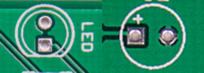
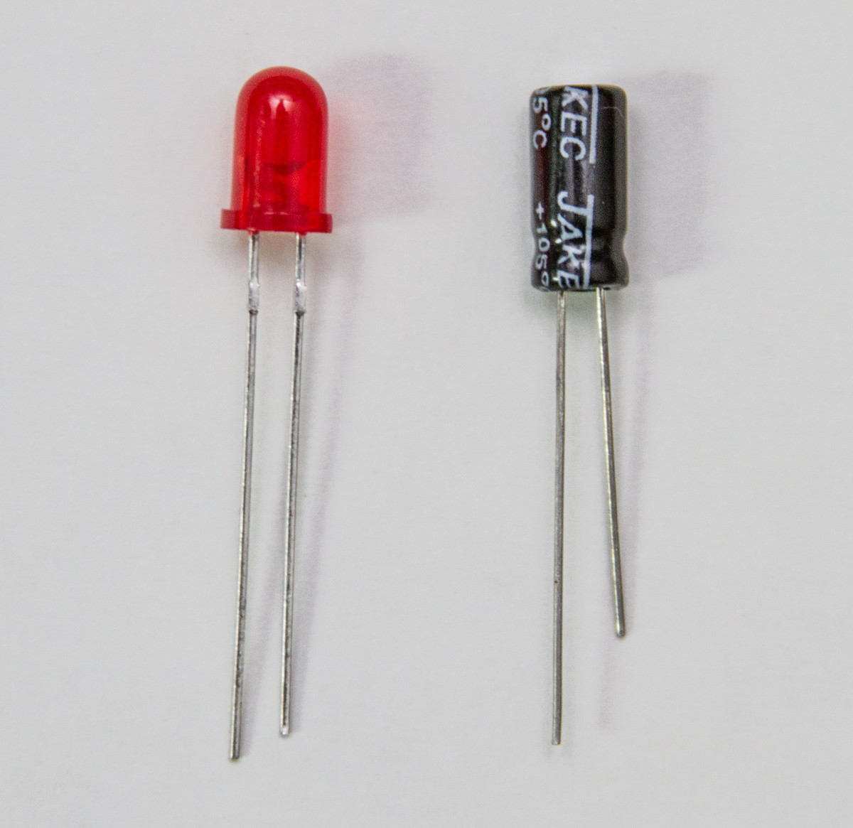
The Electrolytic Capacitors found in your kit are all radial and have to leads protruding from one of the ends. These two leads are polarized. One (Longer) Anode is POSITIVE and the (shorter) cathode is NEGATIVE (there is usually a large negative band on the body of the cap to let you know which lead is negative). There is a graphic designator for each capacitor on your PCB, please make sure to insert the Longer POSITIVE lead into the hole that has the “+” designator by it. LEDs are very similar, but you have the additional help of a flat notch on one side which corresponds to the PCB graphic.
Placing these components in a backwards or reversed position can possibly damage the component, damage the other components, and/or may make your circuit function improperly. Diodes particularly will often appear cracked or burned. If you find that have placed a component in backwards, please try to remove it carefully (search for “How to Remove Through-Hole Components from a Circuit Board” on the web) and place it back in properly. You may need a solder-sucker, or braided solder wick, which can be purchased at Radio Shack.
b. Incorrectly Placed ICs, Resistors, Non-Polarized Capacitors, and Transistors
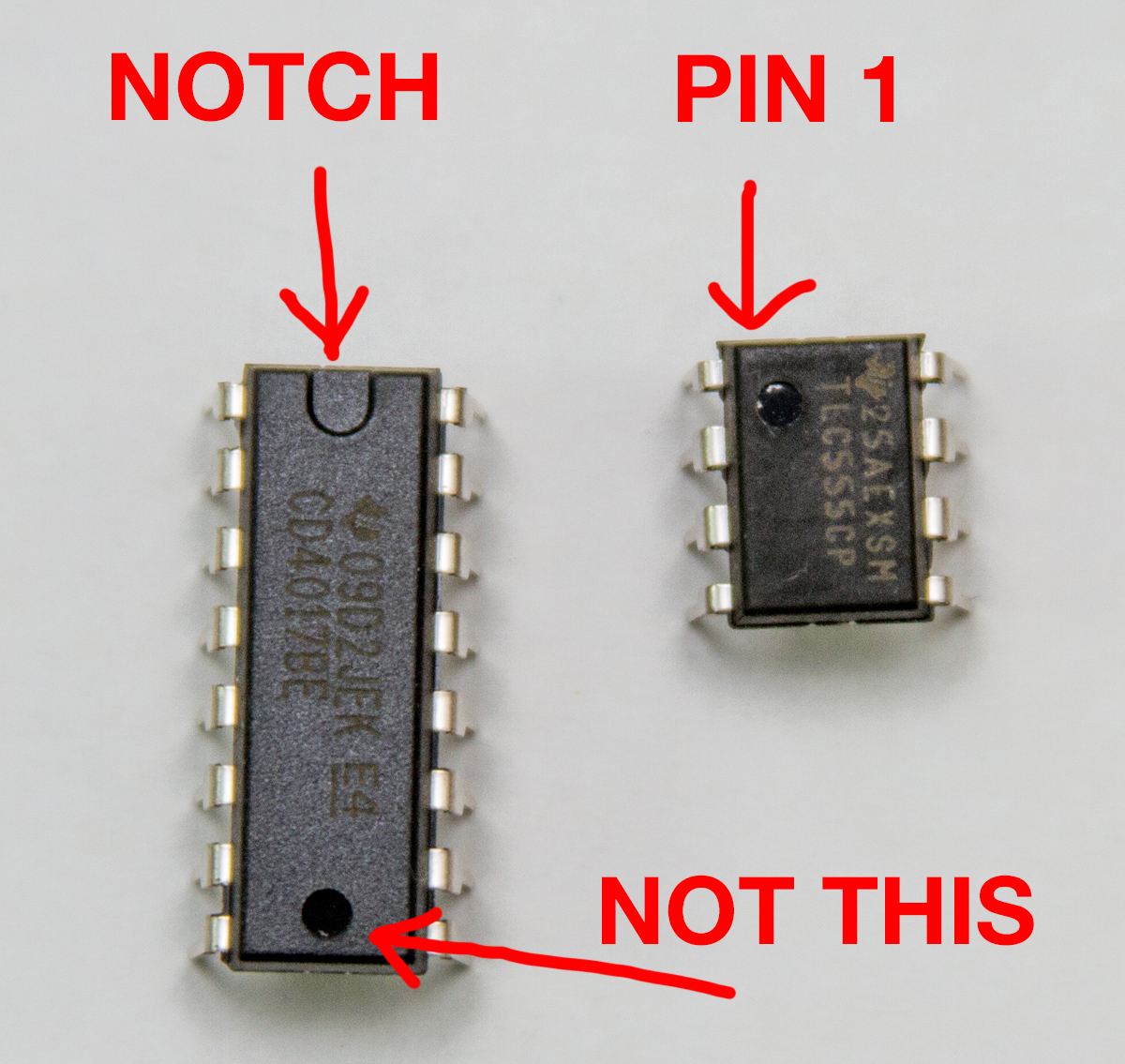
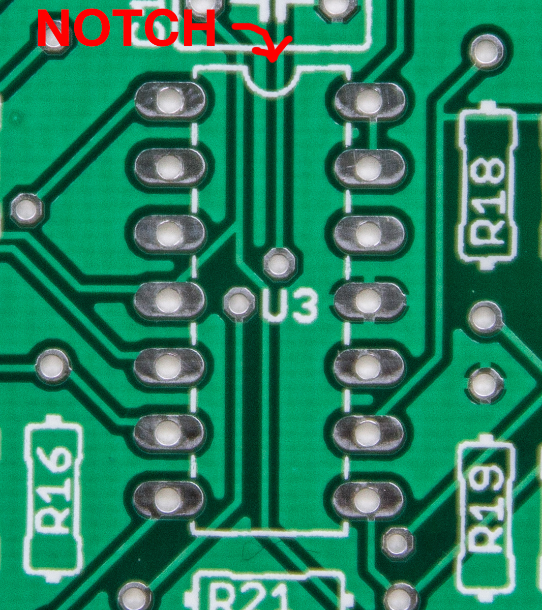
Most ICs or Integrated Circuits are black with multiple legs and have to be properly aligned. The keyed notch on the top side of the IC has to correspond with the graphic notch on the PCB itself. Some ICs have no notch, but do have a circular indicator next to pin #1, which will always be just to the left of the notch, which means that the side of the IC that has the circle is the side that the notch would be on.
Check to make sure that all the IC legs are fully inserted. Sometimes one leg will bend and not insert into the socket properly.
Make sure your ICs are fully seated. You have to push on them a little in order for them to fully seat in their sockets.
Resistors are non-polarized components and can be placed in either direction into the PCB. Some of the resistors we supply may have a beige color (representing 5% tolerance) and some may be blue (representing 1% tolerance). The beige resistors have 4 bands and the blue have 5. Please take a look at the Visual Bill of Materials that came with your kit to find the value of each resistor BEFORE soldering it to the PCB. You can also use our RESISTOR CODE CHART. Don’t refer to our assembly instruction photos for resistor values, use the Visual BOM instead.
Non-Polarized Capacitors are like non-polarized resistors in that it does not matter which way you orient the leads. The graphic on the PCB should NOT have a “+” marking next to these capacitors and is an extra hint not to use electrolytic caps here.
Also note that some ceramic capacitors have a coating that runs down the leg of the capacitor. Make sure when soldering that cap that the coating doesn’t go through the via. You may not get a very good connection if it does.
The transistors in our kits have 3 legs and have to be inserted correctly as well. The 3 legs are the Base, Emitter and Collector. Just pay attention to the key designator on the graphic of the PCB when inserting. Most transistors that we include in our kits have a flat edge, which corresponds to the flat edge on the PCB graphic. Our AC-128 germanium transistors have an extruded metal notch, align this as well with the graphic on the PCB.
NOTE! Voltage regulators can often look like a transistor, this component is not interchangeable, please put them in their respective locations.
2. Soldering Errors – One of the most common build that we run into from customers are a few different soldering errors. Although we are all about cheap and DIY projects, it might be a good idea to invest in a good soldering iron. Most low wattage non-temperature-controlled irons take a long time to heat up to a useable temperature and can damage your PCB. It is actually better to move faster and hotter than slower and colder. This is because the temperature on even a colder soldering iron can damage the vias (holes where you put your components), traces, or components even if your solder is not melting very fast. You want to keep the tip of your iron on your PCB as little as possible. You also do not have to apply pressure to the board when soldering. Excessive pressure can damage vias, traces and soldering iron tips. Old worn out tips can also also cause damage to your traces, because worn out tips often have rough edges can cut your board. Also very large tips and very small tips should be avoided when soldering through-hole projects. We like to use ETP and ETK tips from Weller.
a. Cold Solder Joints are a result of not adequately and evenly heating both the via AND the component lead prior to applying solder. Make sure you touch your iron tip to BOTH the component and via at the same time. Sometimes this is hard to do if you have a large tip, so please find a size where you can heat both easily. A good solder joint should look like a Hershey’s kiss. Here is a photo of some various joints that have been soldered incorrectly. Cold solder joints may not make a good connection in the circuit and can lead to circuit failure. If you would like to learn more about soldering properly, please search the web, as there are so many more and better videos and tutorials then we could ever make here.
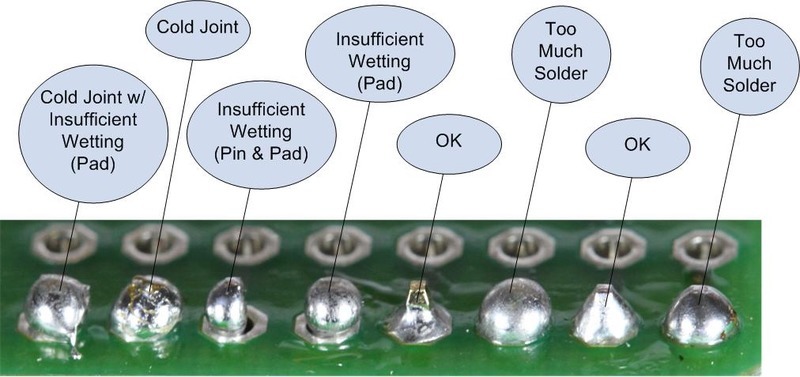
From: https://learn.adafruit.com/assets/1978
b. Damaged Traces or Vias (Accidentally Cut Traces or Vias, Burned Out Traces or Vias, Lifted Vias). Traces and Vias are made up of very thin copper on your PCB. These can be damaged by excessive heat, pressure, cutting, component removal, and when clipping component legs. Since a damaged via or trace can be hard to see at times, it is essential that you use a multi-meter when debugging your project. Check to see if the circuit is making a connection from one point to another. If you are using the ‘continuity’ setting on your meter you may get a ‘beep’ when there is continuity between the points or you may use a ‘diode’ setting that shows you voltage passing. Please also do a web search if you need more information on continuity testing. If a trace is found to be damaged, then you will have to use a small piece of jump wire to connect the points, as they will no longer be connected on the PCB.
For example:
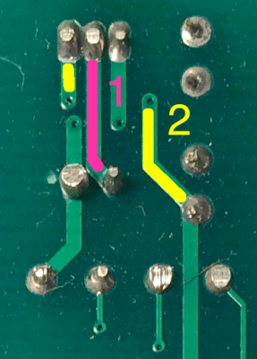
Checking circuit traces
Trace 1 (the pink trace) connects two vias directly on the underside of this board. You can check for continuity between these pretty quickly with a multimeter.
Trace 2 (the yellow trace, starting on the left side of the picture) starts on the bottom side of the board, but then goes to the top side of the board through a tiny via. On the top side of the board, a small trace (not pictured here) runs horizontally over to another tiny via, which connects to the bottom side of the board again. The tiny via on the bottom side of the board then finally connects to a solder point (the yellow trace on the right side of the picture).
If you draw an imaginary line between the two tiny vias in trace 2 on the bottom side of the board, that line will be perpendicular to the traces. Once you have checked traces a few times, you might not have to flip the board back and forth much. You will be able to intuit where they connect on the bottom of the board.
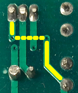
Imaginary Line
c. Solder Bridges. Excessive amounts of solder can connect 2 or more places on your PCB that should not be connected. Be careful not to use so much solder that you cause a bridge. You may need to use a solder sucker or wick to remove this excess solder.
3. Damaged Components
a. Burned Out Components (Too Much Heat From The Soldering Iron). This issue is more rare, but can happen by applying to much heat for too long of a time. Some components, such as polystyrene capacitors, are sensitive to heat and will burn out very quickly.
b. Destroyed Components (Excessive Voltage, Reversed Polarity, Using The AC Adaptor For DC Circuits and Vice Versa). Components can be damaged when they are fed too much voltage, placed incorrectly or backwards or by using the improper amount or polarity of power input. Please be sure to check the polarity on your DC voltage source. The Power Brick that you may use to power your product has a polarity marking which is either Center Positive OR Center Negative. THIS POLARITY IS IMPORTANT, please make sure that you never plug in the wrong polarity. Also, none of our products take AC power directly.
4. Wiring – Many of our kits require wiring. The biggest issues here are correct wiring so that your wires are connecting the wires to the proper holes on the PCB. Also, when stripping wire to insert into the PCB, please strip the wire then ‘tin’ the wires by twisting the strands together then applying a small amount solder to the twisted ends. This will also help eliminate any frayed wires that may spread out onto the circuit board which may connect parts of the circuit that should not be.
Nine times out of ten, following the steps here will fix the problem. If that doesn’t solve it, email us at store@synthrotek.com for help.
Thanks for DIYing with Synthrotek!
I added a comment regarding uncontrollable feedback on the PT2399 delay project.
I have added the project to my Speak and spell circuit bent project, it sounds amazing with the delay run from its own 9v supply. I wanted to run everything from the original power socket but when they are all hooked up together there is uncontrollable feedback from the delay, I’ve added a 30k resister between the Speak and delay which works to a degree but adds attenuation and the feedback is still evident with a high pitch whistle when turning the depth knob remedied only by switching everything off. Any ideas round this? I plan on adding filtering and maybe a sequencer as well so maybe a power distribution board schematic if you have one. I’ve been trying to think along the lines of a modular system but don’t understand how the banana plug idea works, common ground?
Thanks in advance for your time.
Phil,
SE UK.
http://www.synthrotek.com/wp-content/uploads/2014/08/Synthrotek_DIRT_Filter_Schematic.jpg
The power circuit in this schematic, is this the solution?
I’m waiting for parts so sadly I cant breadboard it to see, A diode between every stage should eliminate the signal flowing back right, but have a half wave rectifier effect?
In addition, what’s the benefit of +12v 0v -12v supplies?
What do you do if a eurorack module’s power was connected wrong, red line wasnt correctly labeled. Smoke and caps blew. DO I just need to replace the caps that were blow as well as the ICs? or is the whole module fried.
Hey Patrick,
was this one of our modules that blew? Ours should have polarity protection, so the only things that should actually blow are the diodes at the beginning of the power stage. I would however check everything. Replace the stuff that is visibly broken, then check all diodes, ICs, caps (visual inspection), transistors and voltage regulators.
Best regards,
-Patrick at Synthrotek
DS 8 clone kit
Working thanks to normaling c&s on board! I have an older version with unidentified parts printed on board!
What are the values of:
R101
R100
C100
C101
Please let me know, thanks! Its been frustrating ng not seeing these part on the assembly instructions!
Greetings- I have output from the DS Clone, but only on battery powered amps! Is there a ground connect that I’m missing? I haven’t placed it into an enclosure yet…it sounds on battery powered amps but not through a DI box or AC powered amps!?
Thanks,
Neal
Hello,
Unfortunately I’m not sure I understand which ones you are talking about. On our DS8 clone, we don’t have resistors or caps that are labeled R100, or R101. Is this our PCB that you’re working on?
Best,
-Patrick
Hey Neal,
I’m not sure what is going on with your DS8, but what kind of amp you are using shouldn’t matter to the ds8. I would try using different combinations of cables and ways of hooking it up maybe. Are you using a battery or wall plug to power the DS8?
Best,
-Patrick
I think there’s a mistake on the DS-8 Clone board. C9 is a 47 nF ceramic disk capacitor, but on the board, C9 is shown as an electrolytic.
Hey Bill,
The screen print has not been updated since we changed the value of C9.
It used to be an Electrolytic Capacitor but it is now a Ceramic Capacitor.
As a general rule of thumb, follow the BOM. It will always be the most updated list of components we have.
Thanks for the feedback! Its a very important thing for everyone to be made aware of.
-Zach
Hi there i just put together an MST buffered mult. everything seems to be ok but isnt workiing. when i plug my cv into it, it sends a wild almost noise-signal thats all over the place out to my oscillator. Any classic things i may have overlooked on this?
Sorry to hear you are having issues with your kit.
You should send over some pictures of your board to store@synthrotek.com
I’ll be able to give you better advice as to what could be wrong once I get a look at the board.
-Zach
Hello,
I have finished building a 4093NAND for eurorack. It sounds great and it seems to work fine except for the 3 CV inputs which doesn’t seem to do much if nothing at all. I have used VACTROLS VTL5C3. Are they ok for this project? Could it be possible that I installed them the wrong way around?
Thanks in advance
Guido
Hey Guido,
Have you tried adjusting the trim pots on the back?
Those trim pots along with the vactrols will dictate how much the CV inputs effect the module.
If you’re wondering about the orientation of the vactrols, send over a picture of your board to store@synthrotek.com
While you are at it, send over a picture of the solder side of the board as well! Hopefully we can help to figure out your issue!
-Zach
@Steve Harmon
Thanks Zach. I will check the trimmers and also send pictures. Guido
@Steve Harmon
Hello again Zach,
I checked again and realised that the vactrol are actually installed the wrong way around. I just bought some new ones from your store, as I imagined that that they are damaged now.
But I was thinking..could the vactrol still be functioning anyway? In case I will try to put them the right way around and keep the new ones for spares.
Thanks
Guido
Measure resistance then measure resistance with voltage applied to the vactrol. Use a safe voltage level in order to not blow it. 9v should be enough If the resistance is different with voltage applied then it should be working.
@Steve Harmon
Thanks!
hello,
when doing the diy mst cv to midi, and the mikrophonie, is it a huge issue if i use 1% resistors instead of 5% resistors if the value is unchanged?
Hey Nic,
It isn’t an issue at all. While those builds don’t demand the precision of 1%, they’ll be totally cool if you use it.
Thanks,
Michael
Thank you Michael,
also can you use capacitors that are close in value for the Mikrophonie and can i use a regular guitar style potentiometer. I assuming id have to rework it a bit but that would work, correct? I was trying to think of how to modify one Mikrophonie to be different in sound from the regular built one. I’m building 2 thats why I’m wondering. It’d be neat to have a semi-modified Mikrophonie.
Thaks,
Nic
Problem with RND Build. All the CV Input and Outputs are working Beautifully. The module is working perfectly as long as I’m controlling everything with CV. So here is the problem. Visually The Rate and CV Sliders flash together Simultaneously to the Clock Rate via Gate or Trigger. The Range CV works and lights up when triggered but the Range Attenuator never lights up, yet it does adjust the range when CV controlled yet remains unlit. Nonvisual, when I turn up or down the Attenuators or have no CV’s controlling anything. The Clock and Range remain constant. I can switch through the three different, F,M,S, setting and the clock rate will change but it remains constant, stuck at those initial speeds. In other words the Rate Slider does not adjust the rate speed at all either with or without CV Control… Ant the Range does not adjust when no CV is applied with the Attenuator up or down, Both there lights remain Dark…..
Hi Greg,
Just to make sure I am understanding:
1. the internal clock rate switch (F, M, S) does not affect the clock rate?
2. the internal clock does not affect the changing of the Random Range?
1. The internal Clock Rate Switch (F,M,S) does change the Clock Rate. The Clock Rate Slider does not change the Rate. The Clock CV and Attenuator Slider does and will change the Clock Rate when under CV Control like and ADSR.
2. Correct – The internal Clock does not effect the Random Range. The Random Range CV Jack does work when CV Controlled by an LFO or Soundmachines Light Strip eventhough the Range Attenuation Slider does not light up. The Range Slider will light up when triggered no matter the position of the Range CV Slider.
So basically the top two Sliders is not what’s working.
This is a Great Module under CV Control. Reminds me a lot like a Turning Machine. Love It!!!!!!!!!!!!! Greta Work!!!!!!!!!!!
4093 Chaos NAND Handheld. Makes sounds fine, but CV in has no effect on sound. All pots and switches work as described. No effect upon varying CV input. (CV source verified as changing, works on APC unit to create different pitches/tones.)
Tips and suggestions welcome
Hi Robert, switch the unit off and the CV will work. The CV input is a SAG input, so incoming CV powers the entire unit, which allows for things like dive bombs and electronic drum sounds.
I assembled the 9v DIRT filter unit, but I think something’s not right (probably my error). It only ‘reacts’ when the cutoff knob is between 75 and 100% of full scale, and sometimes produces strange arpeggiated tones (without an input signal), rather than just filtering the input signal. Happy to share photos of my build if they’d help troubleshoot.
– Rob.
Hi, I’m having some trouble with the DIY MST midi to cv. When trying to calibrate it, the voltmeter only reads 5 millivolts on both cv outputs. Gate out reads about 9 volts when i send a signal and the USB midi to din works fine. I mistakenly connected the male headers on the wrong side of the pcb and damaged some of the tracks in the process of removing it. I managed to connect them to other parts of the tracks and I have thoroughly tested the continuity throughout the circuit. Also I originally used a wrong value crystal ( 20.000 MHz instead of 20MHz) . could that have damaged the PIC?
Hi Mike, this is probably a tad more involved than a simple answer, please email us at store – at – synthrotek dot com and we can delve deeper. In general, damaged traces are perhaps the culprit here.
I built a super power blue, i am using a 19volt 3amp power supply. My -12 volt and 5 volt are dead on. My 12 volt line is at about 11.83 volts. I have checked all my solder joints and everything appears fine. If i measure the pins directly on the R7312-D, i have 19 volts going in and 11.83 volts directly on the output pins. Is this normal? Is this an OK voltage for the 12 volt bus? Tried another power supply a 16 Volt 2 Amp and got the exact same voltage (also tried another multi-meter and it was the same). Just want to make sure i am not going to damage anything with under voltage and to see if that voltage is within tolerance and what could possible be the issue.
Hi Sean, this is very normal. The voltage converters have a small tolerance. You are all good.
Hello, yesterday I decided to calibrate my mst vco and I have a feeling I may have broke it in the process. One major anomaly I noticed is that for the past year I have been using my module with the jumber (for the heart beat) connected. However I was able to get all the wave forms but not tuned. The moment I removed the jumper, I never managed to get a signal anymore. I carefully followed every step and reviewed my soldering if something was loosely connected or shorted. I did noticed that many holes where very close from each other but without a clear bridge between them. This was my first euro/modular build ever and never bothered to tune it as I was a beginner and just making noise was amazing to me. Is there any procedure or clues to look at specifically for this build (MST VCO module) to debug the problem. The build guide does warn you about the polysterene capacitor being heat sensitive. Is there a way to tell if its broken. Can it be swapped by a different capacitor?
If anybody got some tips on debugging this one would be amazing.
Hi Marc-André, hit us up on email, I think we might have deal with this specifically.
Hi i am having trouble with the nandamonium. The osc3 on the cv1 side doesnt work. I took the pot off and its fine. What else should i look for?
Hello, I’m guessing the switch next to the OSC3 is turned to ON, correct?
Have you tried reflowing your solder joints? If not, do that, and check your component values too. Something could be mixed up, causing attenuation of the signal.
Yes it was on. Also i just got done reflowing every solder joint on the board and now osc1 and osc3 on cv1 dont work. Osc2 works fone and cv2 all work fine. Im stumped. I swapped the isc back and forth and the problem stayed on cv1 side.
Hi Dan, send some pics of your build to me at info@synthrotek.com, let me see if something pops out to me.
Thanks!