This product has been discontinued.
Important Links
Product Page
Assembly Instructions
Assembly Notes
Bill of Materials
Schematic Page
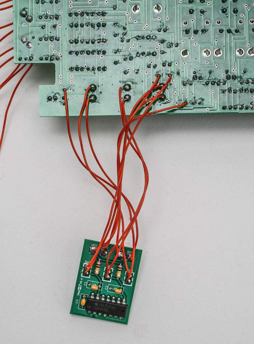
16 Step MOD
Drill Template
Capacitor and Resistor Lookup Guide
Here are some notes from the recent assembly by our new tech guru.
1) If you are doing the MOD along with the assembly of your 16 step, it’s easier to do MOD assembly instructions steps 1 and 2 before you start actual assembly of the 16 step. This means, don’t populate C27, C28, R89 and R90. And then cut the traces as indicated in the MOD assembly instructions. The rest of the steps of the MOD assembly instructions can be completed after the 16 step is assembled.
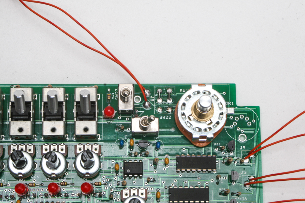
2) DO NOT populate SW22. Previously we noted in the MOD instructions that SW22 was not required. Well as it turns out, it’s much better to just not populate it at all. SW22 was intended for switching between the internal signals and the DIN connector. Populating SW22 and not having it switched in the onboard position will cause erratic behavior. This is the most common issue! So, it bears saying again. DO NOT populate SW22. Instead, short the switch as shown in the image below.

3) SW17, the rotary switch is oriented so that the tab is on the right side. See the photo above. We bent the tab down to make it more noticeable and it also makes fitting into the 16 step case we have easier.
4) The DIN connector is not included in this kit. The DIN was placed in the circuit for future features however those have not yet come to fruition and will likely not happen before the 16 step is redesigned to be more assembly friendly.
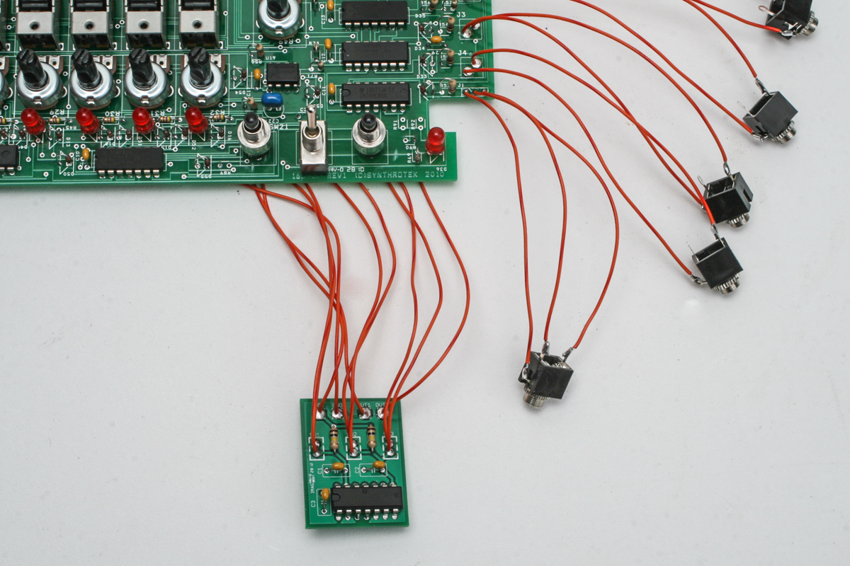
5) J1 is not a standard stereo jack. J1 must be shunted, ie the ring and tip are shorted together when nothing is plugged into it. This is essential for the clock signal to propagate properly. See the picture below to see what a shunted jack looks like. There are others, but this is the most common.

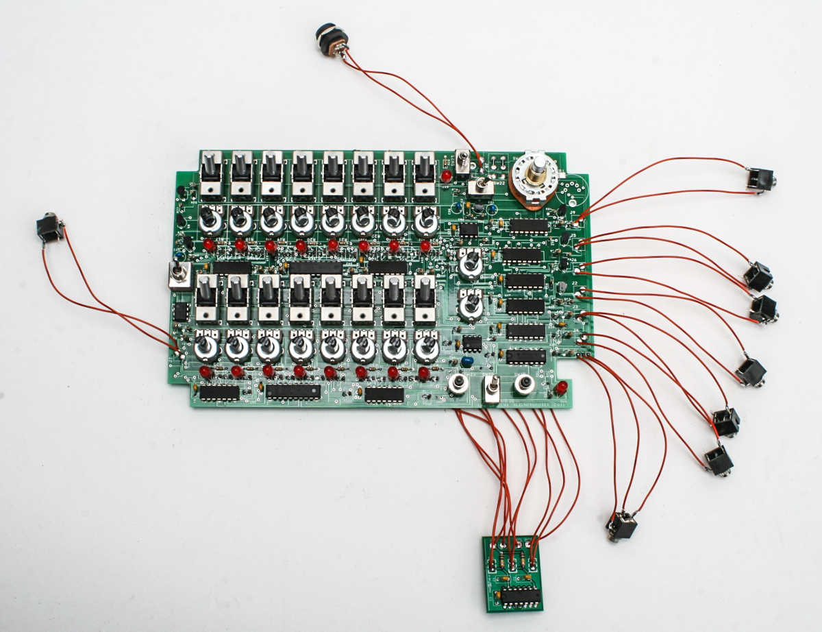
6) Wiring for J1 can be seen in the above photo.
7) Populate and channel switches before the 10k potentiometers. The switches are shorter than the pots, so if you do the pots first the table will not hold the switches tight to the board for you making soldering easier.
8) Pay special attention to the orientation of U21 (TLV2370). The dot or notch goes toward the top.
9) D1 & D38 and D2 & D39 are close enough that they can easily be shorted together if you are hasty or sloppy.
10) The following components have vias near them that could cause the components to be placed incorrectly, so care should be taken when placing them: R64, R88, R24, R43, R81, R80, C22, C14, C13, C17, C10, and C9
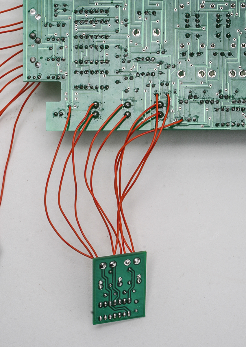
Below are a few more pictures of our recently completed 16 step you can look at if you have more questions. Also, don’t hesitate to email us if you have questions.