


This is an older version of the PCB Mounted Rat Clone that has been discontinued. Find the new version HERE.
Important Links
Product Page Store Page Bill of Materials Capacitor and Resistor Lookup Guide
Looking for Parts?
- LM308 OpAmp IC
- 9mm Vertical Potentiometer – 20K Linear
- 9mm Vertical Potentiometer – 100K Linear
- 9mm Vertical Potentiometer – 100K Audio
- 1/4″ Mono Audio Jacks – PCB Mounted
- 1/4″ Stereo Audio Jacks – PCB Mounted
- 3PDT Guitar Pedal Stomp Switch
- 1590B Pre-drilled case for Guitar Pedals
Welcome to the Rat Clone (PCB mount) assembly instructions. Except for the battery clip this kit does not use any wiring and everything is attached directly to the PCB, making it easy to make a very nice looking build. Lets get started!
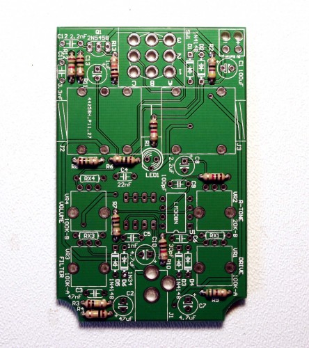
BOM Layout
If you’ve received your kit and are ready to build, the first step is to ensure you have all of the parts and familiarize yourself with the PCB and where the parts will be going. Check your kit against the Rat Clone (PCB mount) BOM. If you are missing anything let us know and we will ship you the part.
Assembly
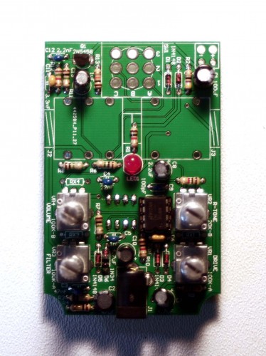
Resistors
There are 12 resistors to install – resistors are not polar and may be mounted in either direction.
Diodes & LED
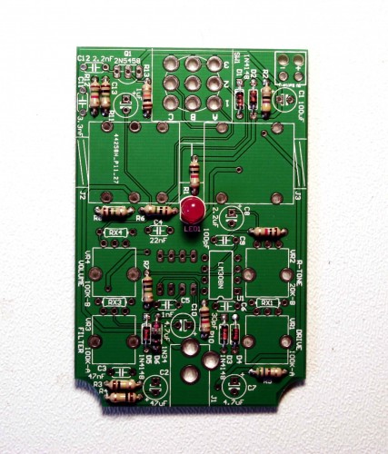
There are six diodes and one LED – all but D6 is a 4148 diode. Take care to align the flat edge of the LED with the flat edge on the silkscreen and the black line on the diodes with the corresponding lines on the silkscreen. You may want to forego mounting the LED flush with the PCB and use a longer lead length if installing the circuit in a case.
Capacitors
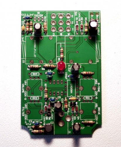
There are six electrolytic and six ceramic capacitors. Align the positive symbol on the silkscreen with the long lead of the electrolytic capacitors.
Electrolytic capacitors and diodes are polar components, and your circuit will not function with polarity reversed.
IC Socket, DC Jack, and Transistor
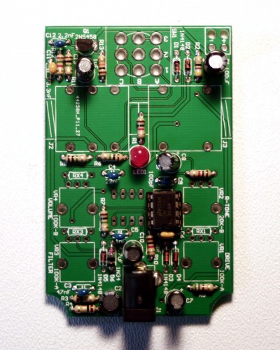
Next we will install transistor, IC Socket, and the DC jack. Align the flat edge of the transistor and notched edge of the IC socket with the corresponding markings on the PCB. Install the LM308 IC with the notch/pin 1 facing the notched edge of the socket.
DIP Switches
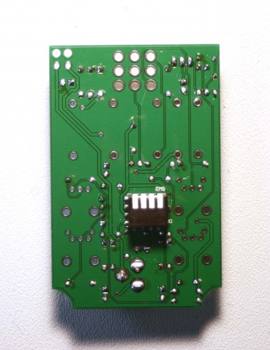
Now flip the circuit over and install the DIP switches with the switch edge aligned with the silkscreen markings.
Potentiometers
Next you will want to install the pots (VR1-VR4). When soldering the pots into place you will want to also solder in the side-clips to ensure that the pots are secured to the PCB and will not easily come loose.
When installing the pot, some pots come with nubs near the shaft that may get in the way of installing the circuit into a case. Check for a nub and clip as necessary.

Don’t forget to cut the nubs on the potentiometers as neccesary.
Stomp Switch, Audio Jacks, and 9v Battery Clip
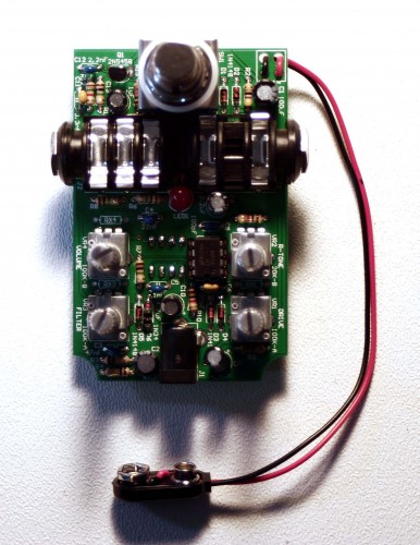
We’re almost done! The audio jacks will be easy to install, just make sure you install the mono jack into side that only has the two holes and not into the mounts for the stereo jack, which will have a total of six holes. When you install the stop switch, make sure that the blue plastic edges face the top and bottom of the PCB and the metal-lined edges face the sides of the PCB. If you can’t get the stomp switch to go in, don’t force it – try it in a different direction.
Project Completed
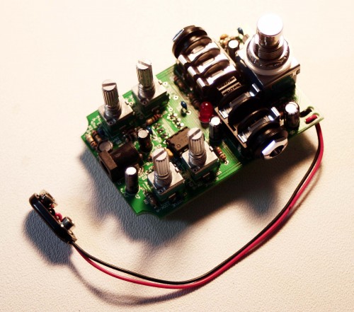
Congrats! Your Rat Clone is complete. Hook it up and have some fun!