


Important Links
Product Page
Store Page
Console Quick Start Guide
Eurorack Quick Start Guide
9V Battery Placement
Assembly Instructions
Bill of Materials
Capacitor and Resistor Lookup Guide
Thank you for picking up a Nandamonium! Here are the instructions for the Mark II Nandamonium (version 2.3). If you are looking for the original Nandamonium assembly instructions, CLICK HERE. Happy assembling!
RESISTORS & DIODE
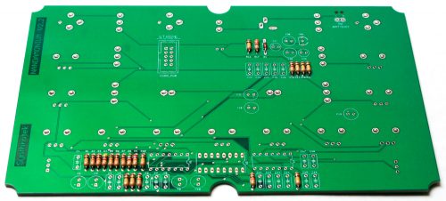
Resistors are non-polarized, so it doesn’t matter which direction you put them on the PCB, but it will help with any troubleshooting that may arise if you line up all the tolerance bands (usually a gold stripe) on one side. This makes it easy to read the color codes on the resistors.
Diodes are polarized, so make sure when you are populating them to get the cathode band (black stripe) aligned in the same orientation as indicated on the PCB by the stripe.
Once they are populated, flip the project over, and solder them in place, clipping the excess leads.
IC SOCKETS
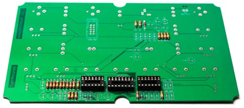
Next up are the IC sockets. Take care when populating these to not bend any of the legs, and to line up the notch in the end with the same notch that is displayed on the silkscreen. When you have them populated, carefully flip your project over and solder everything in place.
A trick to getting these nice and flat is to solder pins on opposite corners of the socket, and then reflow the solder joints while gently pushing on the top of the socket to seat it flat against the PCB. Then continue on and solder the rest of the pins, periodically checking for flatness.
CERAMIC CAPACITORS
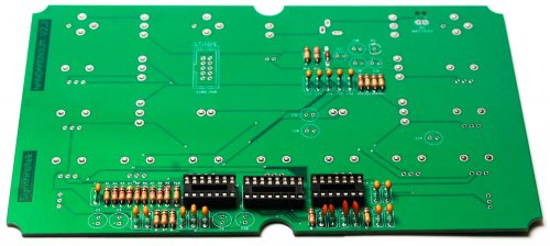
Now we can populate the ceramic capacitors. These are non-polarized, so they can be inserted either direction. Once they are in, carefully flip over your project and solder them in place, clipping the excess leads.
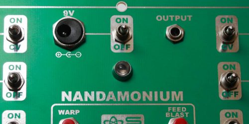
VOLTAGE REGULATOR & EURORACK POWER SOCKET
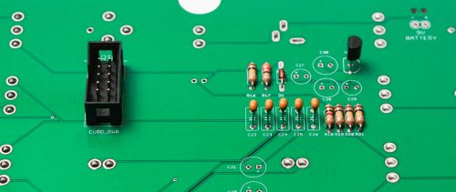
First place the voltage regulator in the PCB as shown above. This is polarized, so make sure when populating you align the flat edge of the component with the corresponding flat line on the silkscreen.
*OPTIONAL* – If building the Eurorack version of the Nandamonium 2.3 place the 10 Pin Shrouded Power Connector as show above. Make sure when populating this that the notch in the header is lined up with the notch designation in the silkscreen.
ELECTROLYTIC CAPACITORS
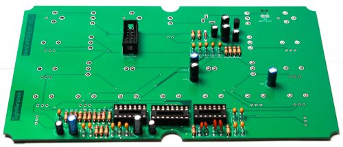
Next up are the electrolytic capacitors. These are polarized, so take care when populating them. There is a small ‘+’ on the PCB that indicates where the longer of the two leads needs to go. When populated, the stripe on the capacitor should be facing away from the ‘+’ symbol. When you are happy with their placement, carefully flip your project over and solder everything in place, clipping the excess leads.
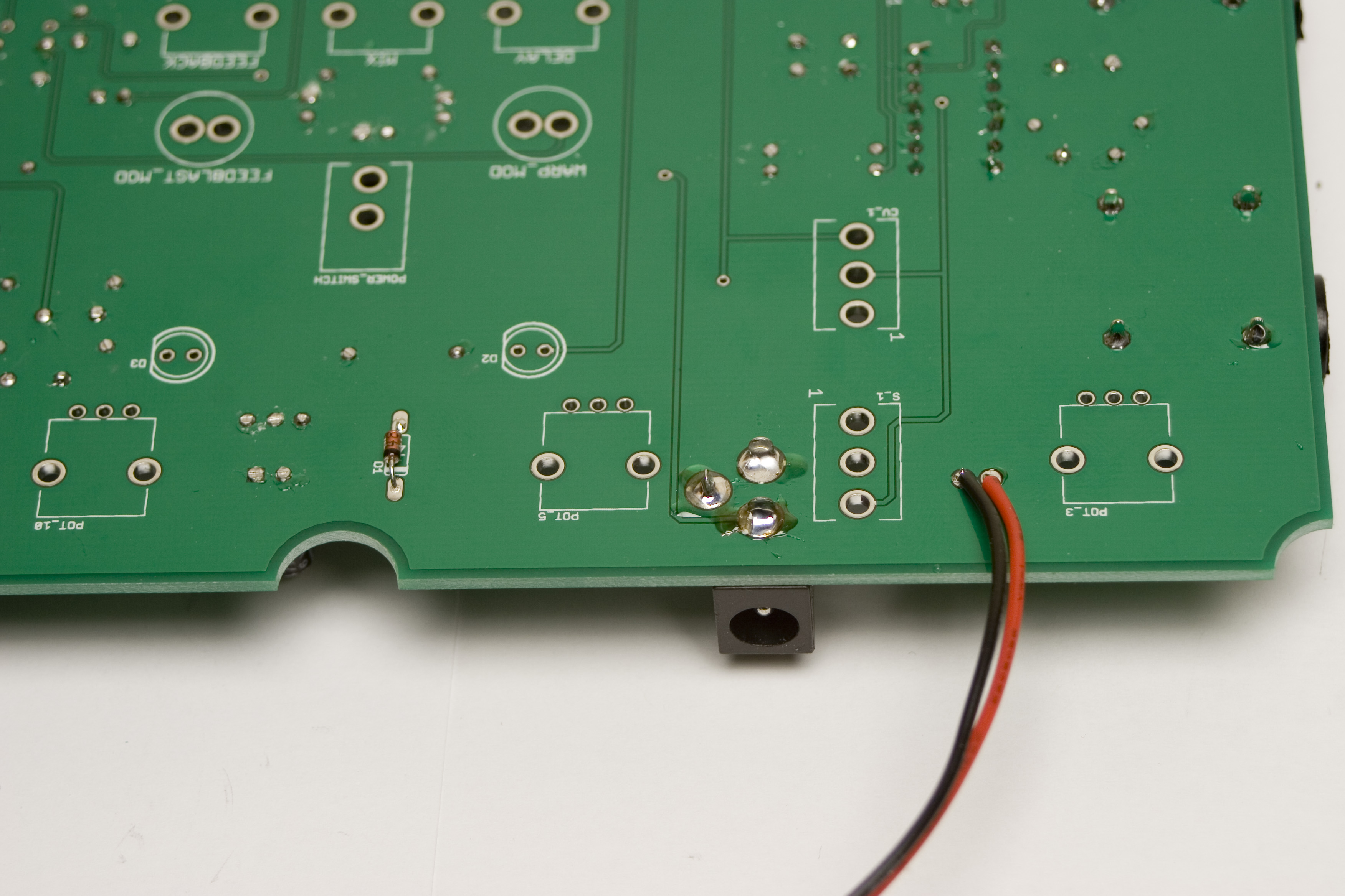
9V BATTERY CLIP
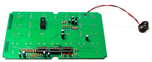
*OPTIONAL* Disregard this stage if you are building the Eurorack version
Thread both red and black wires through the tension holes and into the PCB as shown above. Red to “+” and black to “-“. Solder in place.
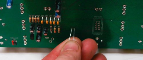
Eurorack LED
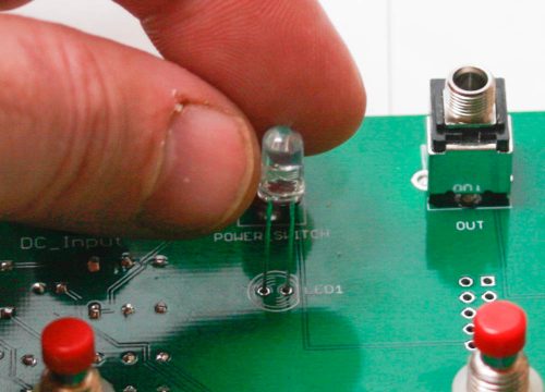
**Eurorack Version** – Bend the LED as shown below, make sure the FLAT side of the LED is oriented toward the FLAT side of the silk screen.
Solder the LED so that it is touching the PCB as shown below
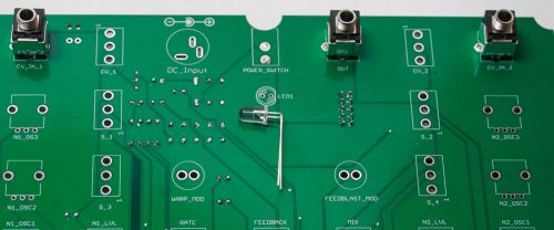
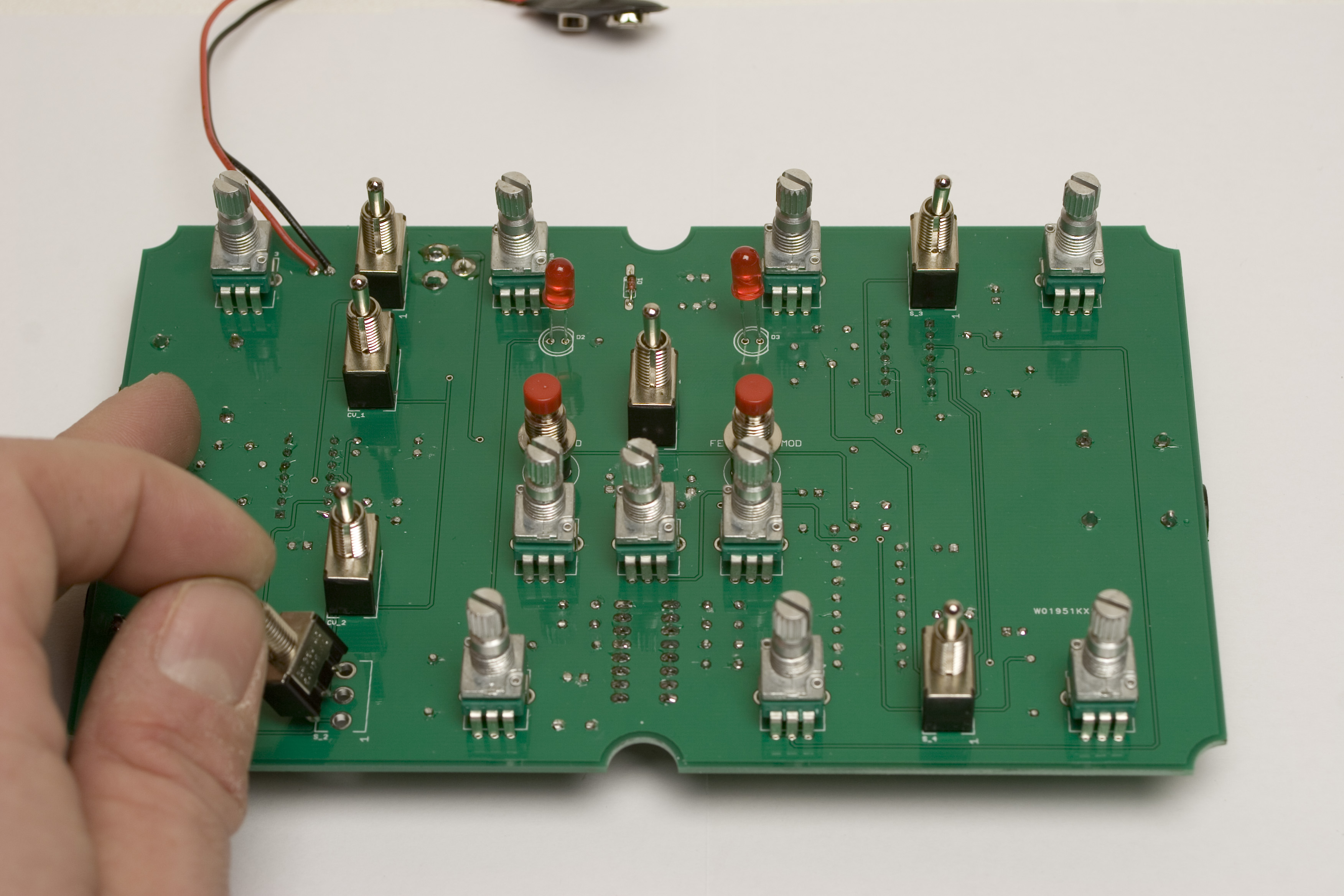
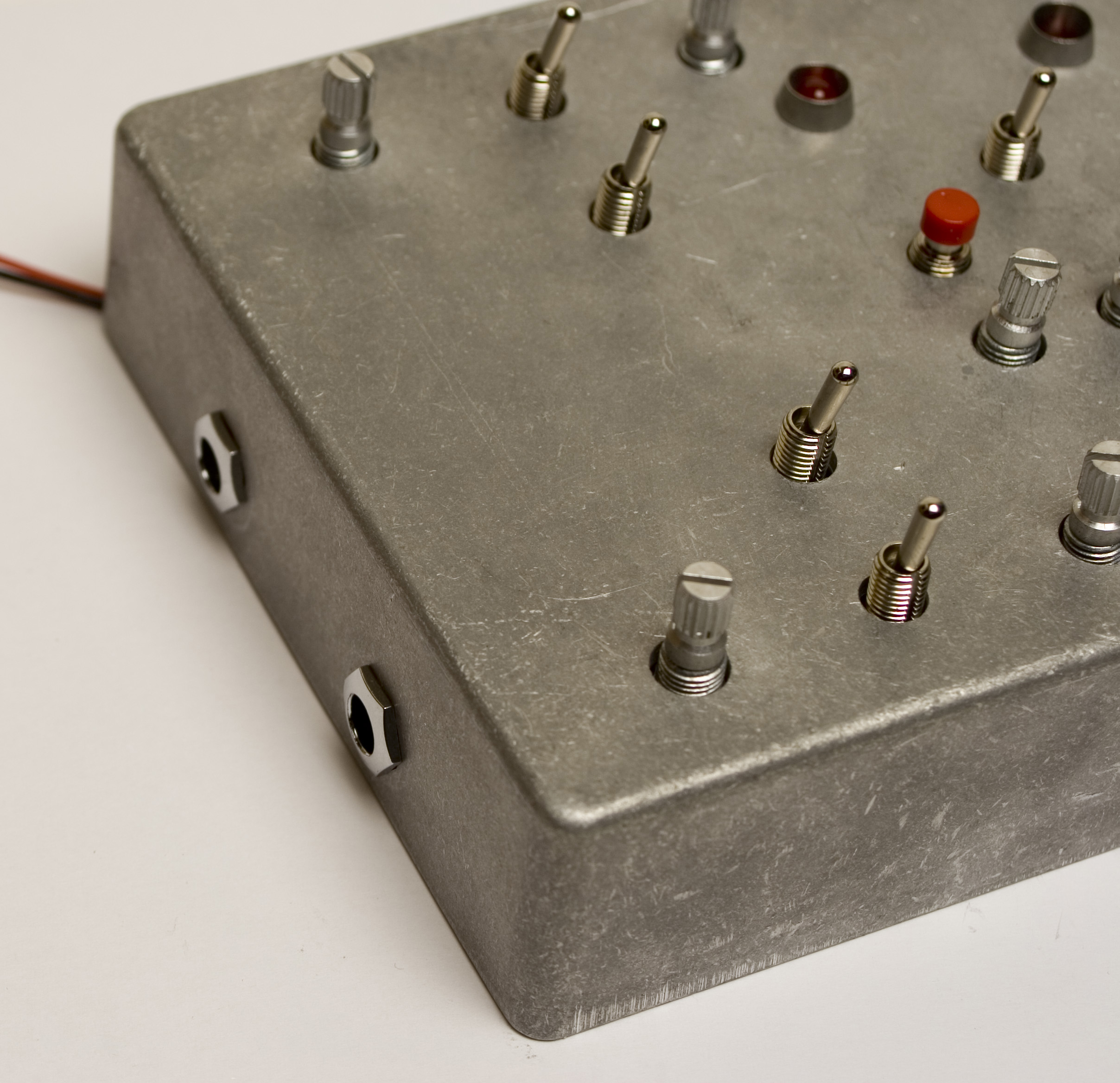
JACKS, SWITCHES AND POTS
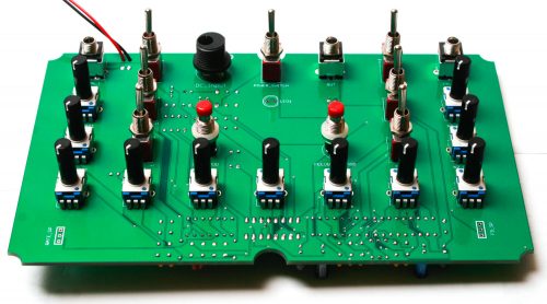
IMPORTANT: Wait to solder the following components until you have secured them all to the panel!
Place the jacks, switches and pots into the PCB as shown above.
*OPTIONAL* DO NOT populate the DC Jack or SPST switch as shown above if building the Eurorack version. If building the console version, place the DC Jack and SPST switch.
Add the spacers to both the push button and toggle switches.
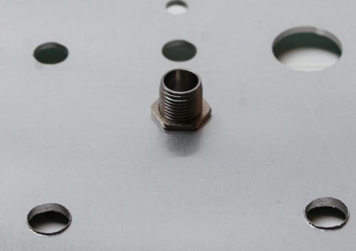
CONSOLE VERSION LED BEZEL
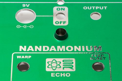
On the console version, add the LED Bezel as shown above and tighten the nut as shown below.
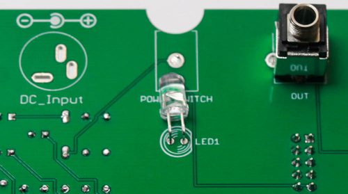
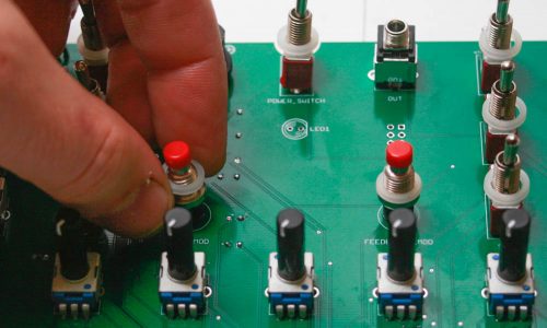
Console LED
**CONSOLE VERSION** – Place the LED into the PCB. LEDs are polarized and need to have the flat side the LED match the flat side on the PCB silkscreen. DO NOT SOLDER IN JUST YET! Wait until you place the panel on in order to position the LED inside the LED Bezel or properly in place behind the transparent area on Eurorack front panel.
EURORACK POWER JUMPER
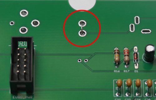
The Eurorack version of the Nandamonium needs to have the Power Switch pads jumped in order for the unit to turn on. Take a left over resistor leg and bend it over as shown below and place it in the PCB at callout “Power_Switch”. Solder and clip the excess leads.
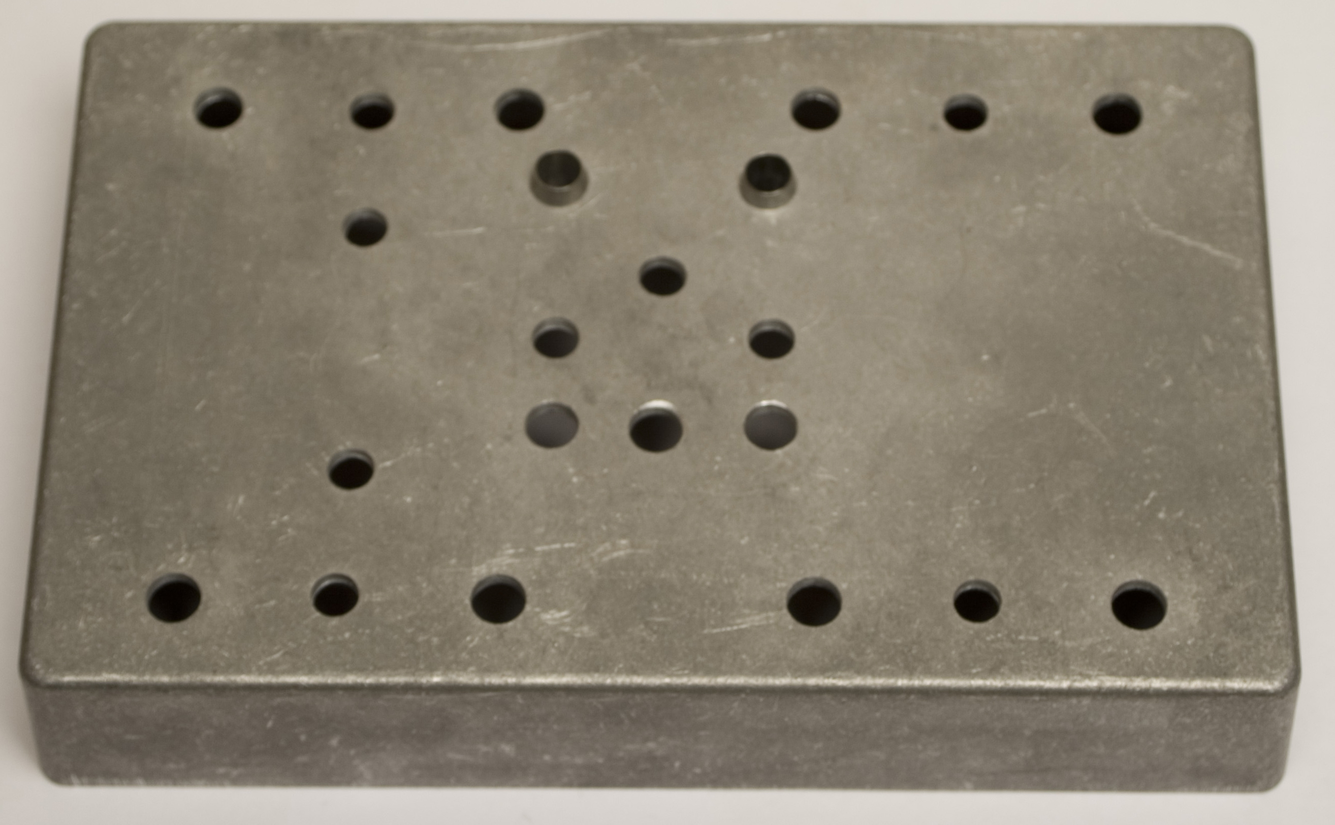
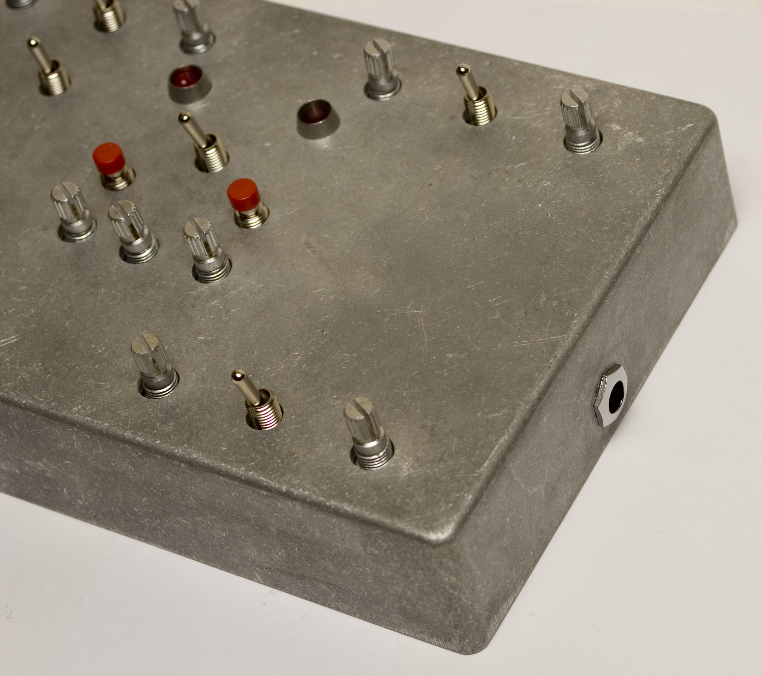
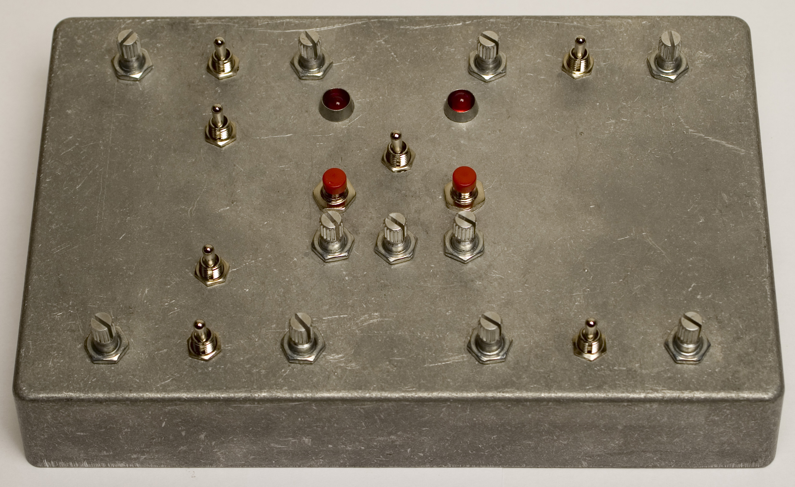
PANEL PLACEMENT
Take either the CONSOLE or EURORACK Panel and carefully place it over the project.
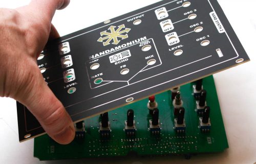
Now you can add all of the jack and switch nuts and gently screw down tightly!
**CONSOLE ONLY** – One you have added all of the nuts, push up the LED in the panel LED Bezel.
Solder all components into place.
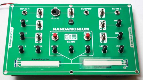
SOFT POT PLACEMENT
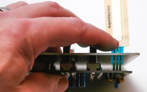
On both the CONSOLE and EURORACK versions take the soft pots and place them through the slot on the panel and then into the three holes in the PCB below.
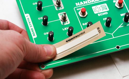
Take your time and get this part right! Place the soft pot all the way back toward the slot and then peel off the adhesive backing and press in place.
Do this for both sides, then solder into place.
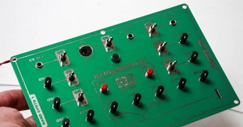
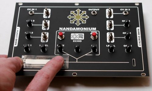
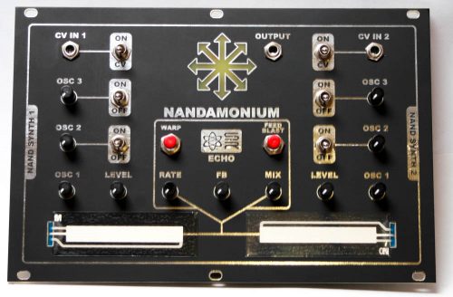
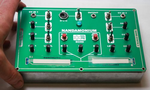
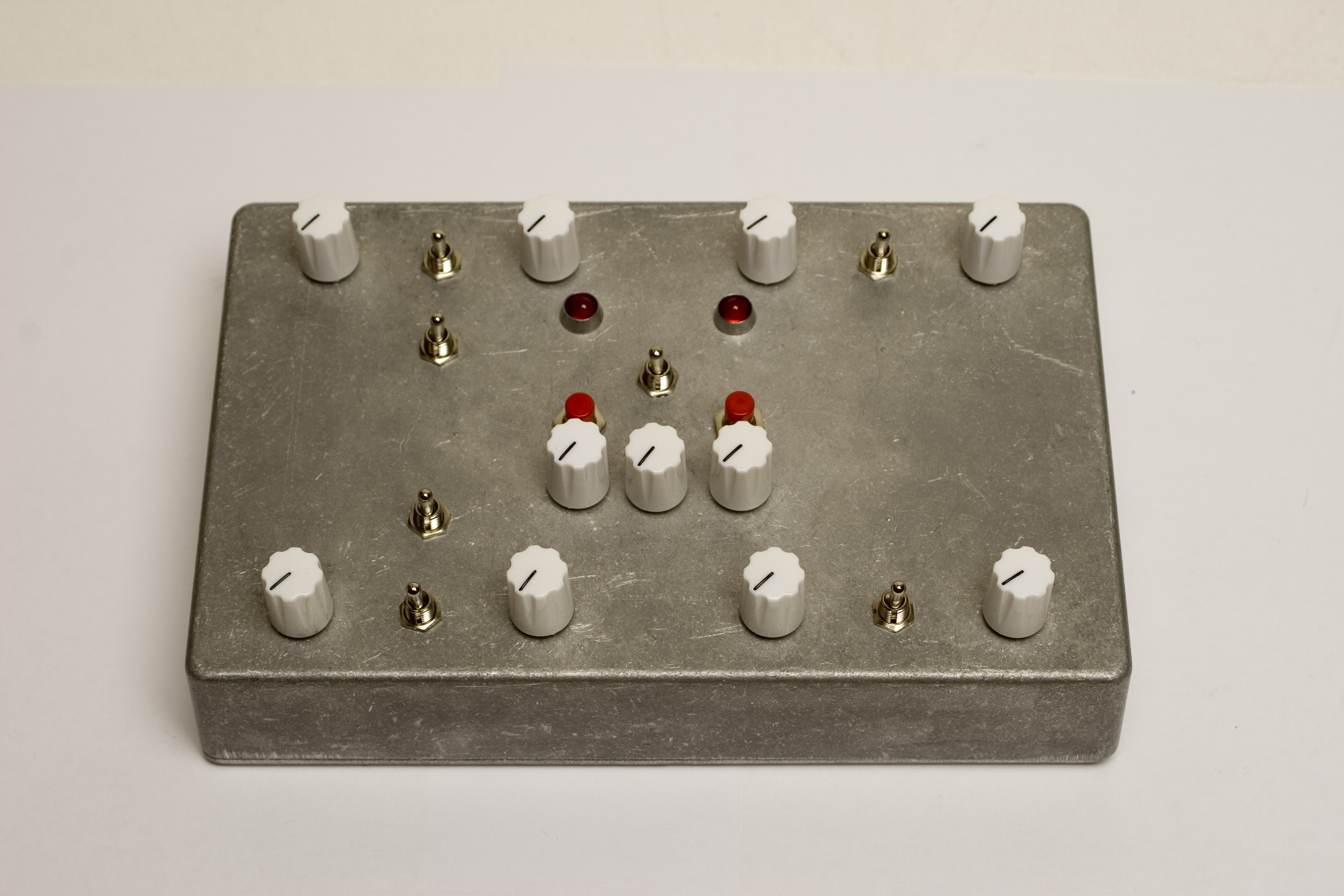
FINAL LOOK
Congratulations! You have built your Nandamonium. Plug in and play!
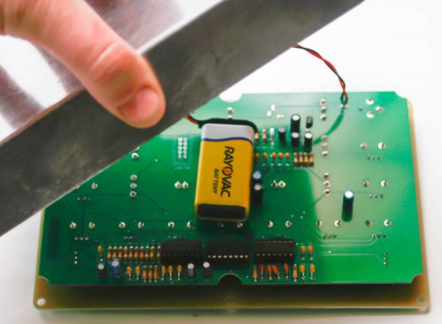
CONSOLE 9V BATTERY PLACEMENT
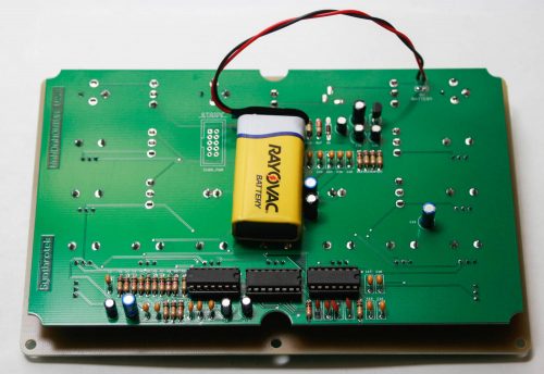
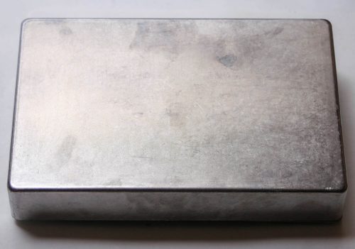
At first glance it might appear that a 9V battery won’t fit inside the aluminum case. It will actually fit very nicely! Place it on the board as shown above.
Take the case and place it over the back of the PCB as shown above.
Now take the case and carefully turn it over. The 9V battery should not move around.
Finally, screw down the panel onto the case.
ORIGINAL NANDAMONIUM INSTRUCTIONS BELOW
Welcome to the assembly instructions for the Nandamonium! This product features a double nand drone and built in delay functionality. The Nandamonium takes a standard 9v center negative power adapter.
If you’ve received your parts and ready to build, the first thing you should do is to check to make sure you have all the parts. Check your kit against the Nandamonium BOM. If you’re missing anything we’ll send it to you free of charge.
Soldering the Components
Attention: Changes may occur after the Assembly Instructions are created and the photos may not reflect those changes. Always use the BOM to verify the placement of components.
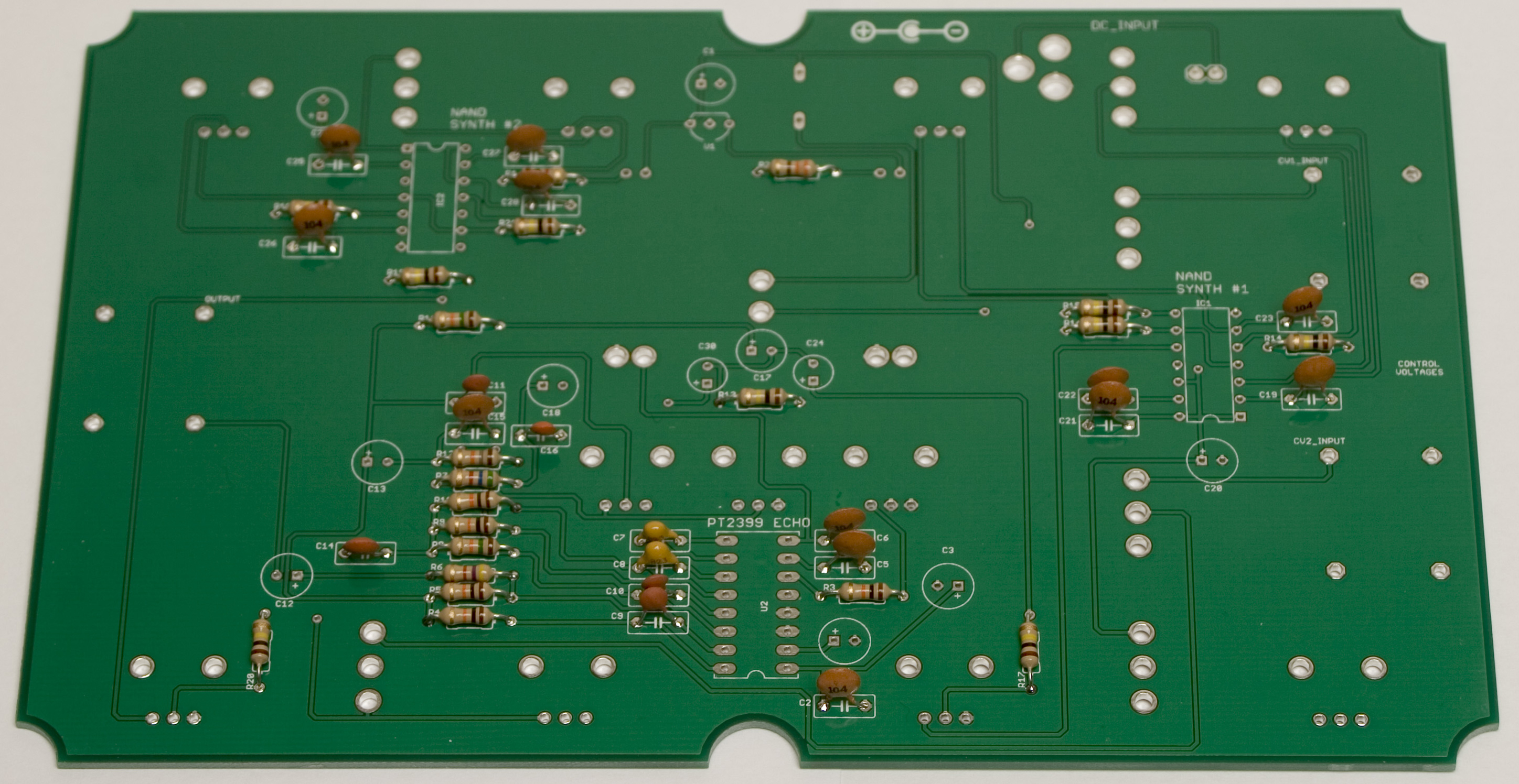
Resistors
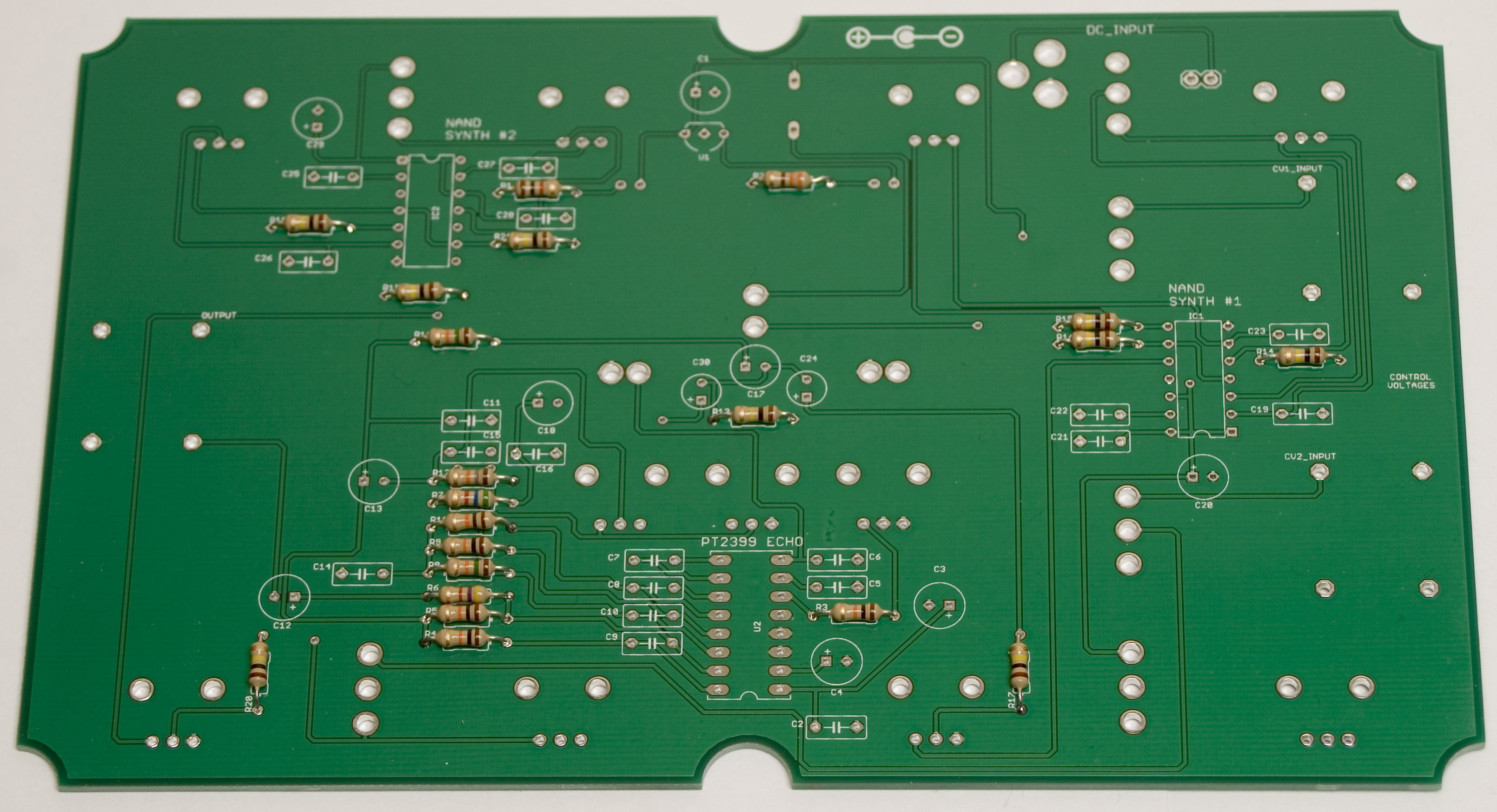
Nandamonium Assembly Step 1: Resistors
First solder all the resistors into place. Resistors are not polar sensitive so you may install them in any orientation.
Ceramic Capacitors
Nandamonium Assembly Step 2: Ceramic Capacitors
Next, solder all the ceramic capacitors in place. They are not polar sensitive, and can be placed any direction. It is suggested to place them in such a way that you can read them easily later on.
IC Sockets
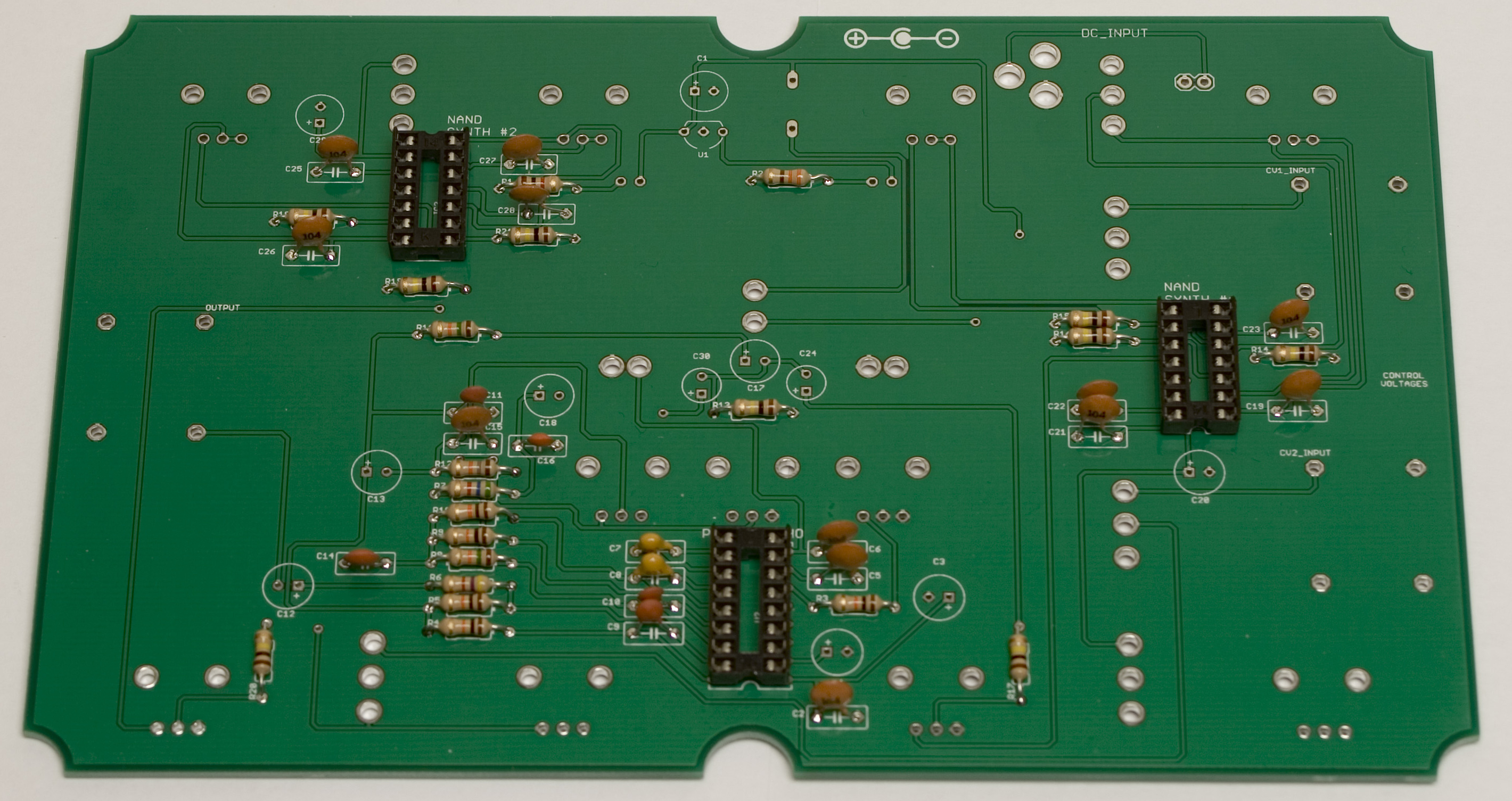
Nandamonium Assembly Step 3: IC Sockets
Now solder the IC sockets into place. They are notched on one end, and need to be placed so that they match the silkscreen on the board. A tip for soldering the IC socket flat to the PCB, first solder two opposite corners of the socket and then make sure that you get the socket flush to the PCB. Afterwards solder the rest of the pins and touch-up the two first pins as necessary.
Electrolytic Capacitors & Voltage Regulator
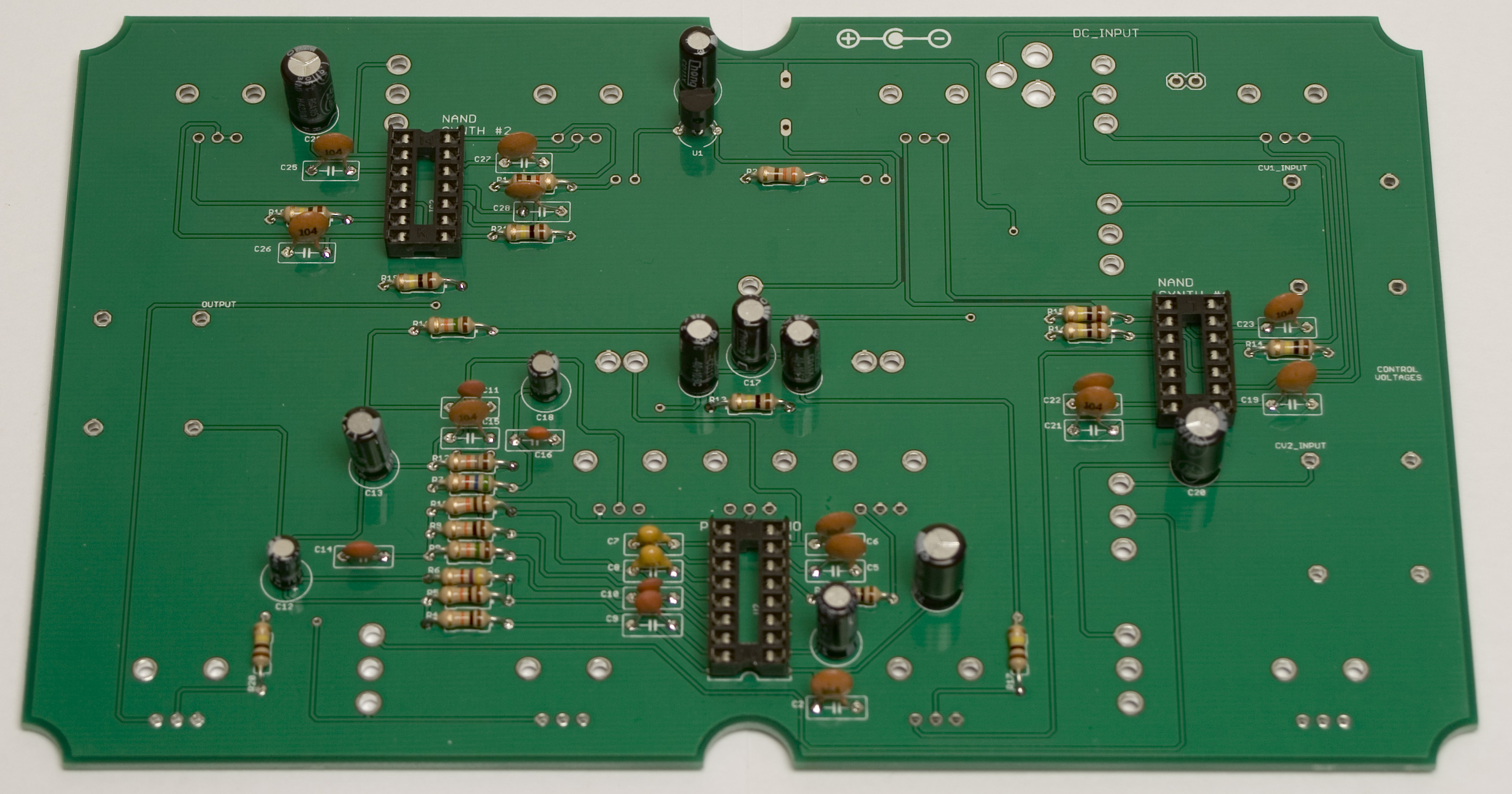
Nandamonium Assembly Step 4: Electrolytic Caps
Now lets solder the electrolytic capacitors to the board. They are polar and need to be put in with the longer lead going into the via with the + next to it. The voltage regulator is polar as well, and needs to be matched to the silkscreen on the PCB, with the flat side on the regulator matching the flat side on the PCB.
Power and Audio Jacks
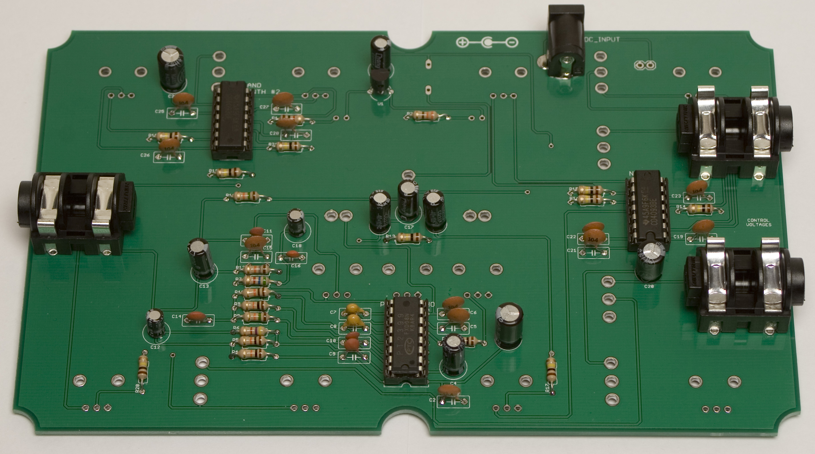
Nandamonium Assembly Step 5: Jacks
Next up, place the actual ICs into their sockets, matching the notch on the chip to the notch on both the PCB silkscreen and the socket you put in earlier. The DC jack goes on the side of the board with the silkscreen writing that says “DC_INPUT”. Try to keep it perpendicular to the edge of the board, and push it as far back from the edge as possible. This will help avoid fitment issues later. The mono jacks go on the same side of the board, just ensure they are flat to the board before soldering all the legs.
Diode & 9v Battery Clip
Nandamonium Assembly Step 5: Diode and 9V Clip
Flip the board over, to the side that has the silkscreen for the potentiometers. There is a place for a single diode near the top of the boards. Go ahead and solder this in now, matching the stripe on the diode to the striped part of the silkscreen. Solder the 9v battery clip in so the wires match the picture above. The negative via will have what looks like a cross through it.
Un-soldered Controls
Nandamonium Assembly Step 6: Controls
Keeping the board with the battery clip up, place all the controls on the board (potentiometers, switches, and LEDs) but DO NOT SOLDER THEM YET. We will need to fit all this into the case before soldering. Make sure that all nuts have been removed from everything before trying to fit it in the case, otherwise, it won’t work.
Some pots come with nubs near the shaft that may get in the way of installing the circuit into a case. Check for a nub and clip as necessary.

Don’t forget to cut the nubs on the potentiometers as necessary.
Case Prep
Nandamonium Assembly Step 7: LED Bezels
Before we fit the board into the case, the LED Bezels need to fastened to the case, through the holes shown above.
Assembly
 After wrestling the Nandamonium PCB into the case, start the nuts for the output, cv1 and cv2 jacks on the sides before tightening any of the nuts on the top. This will hold everything in place, and line it all up.
Final Fitment
Nandamonium Assembly Step 9: All Tight!
Now we are ready to put the nuts on everything and tighten them up fully. Just be sure not to over-tighten any of the controls. The pots should move just a little bit as you tighten them all the way up.
Next just flip the Nandamonium over and solder up all the leads sticking through, being careful not to touch any caps or ICs with the soldering iron. After that, just close up the case, and install the knobs, and you’re good to go!
Finished Nandamonium
Afterwards, your Nandamonium should look like this. Congratulations on successfully completing the build!
Hi, can i purchase the case from you guys as well? I just received my circuit board today in the mail.
Thanks.
Those cases are currently sold out but check back soon we should be getting more within a few weeks.
hi
i just finished soldering i just wondering about the led,s there is no marking on the pcb ?
i did not solder them yet .
also no solder on the pots or switches.
and it does nog seem to do anything .
i raised the jacks. because i want to mount them in a euro rack .
is this a problem?
sam
Hey, Sam
You’ll notice that the silkscreen has a flat side on the circle around the LED’s place and that is to indicate the negative or short leg.
Cheers,
Michael