


Important Links
Product Page
Store Page
Assembly Instructions
Bill of Materials
Capacitor and Resistor Lookup Guide
 Thank you for purchasing the Synthrotek Space Drum Synth Kit! This is an easy to intermediate build. It is very important to get all the components properly soldered into the PCB in the correct placement. If you feel like you can handle it, please proceed! If not, get some help from a friend with experience or purchase a fully completed unit.
It is recommended to double check your kit against the Bill of Materials to ensure you have all the parts before beginning the build.
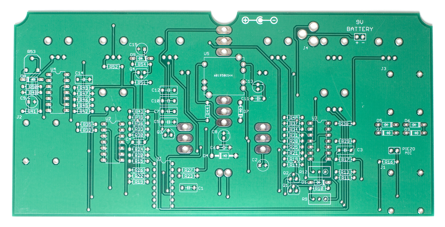
Let’s begin!
Diodes
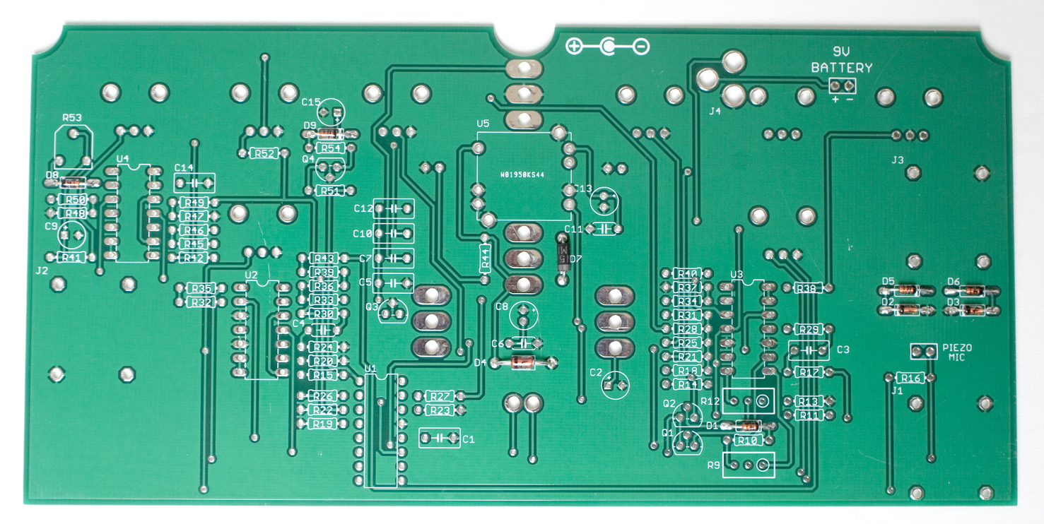
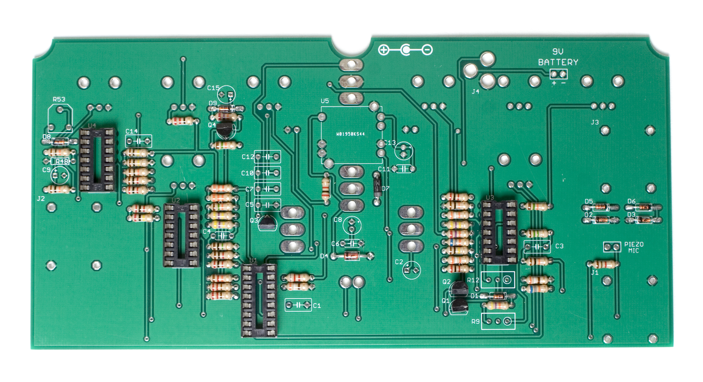
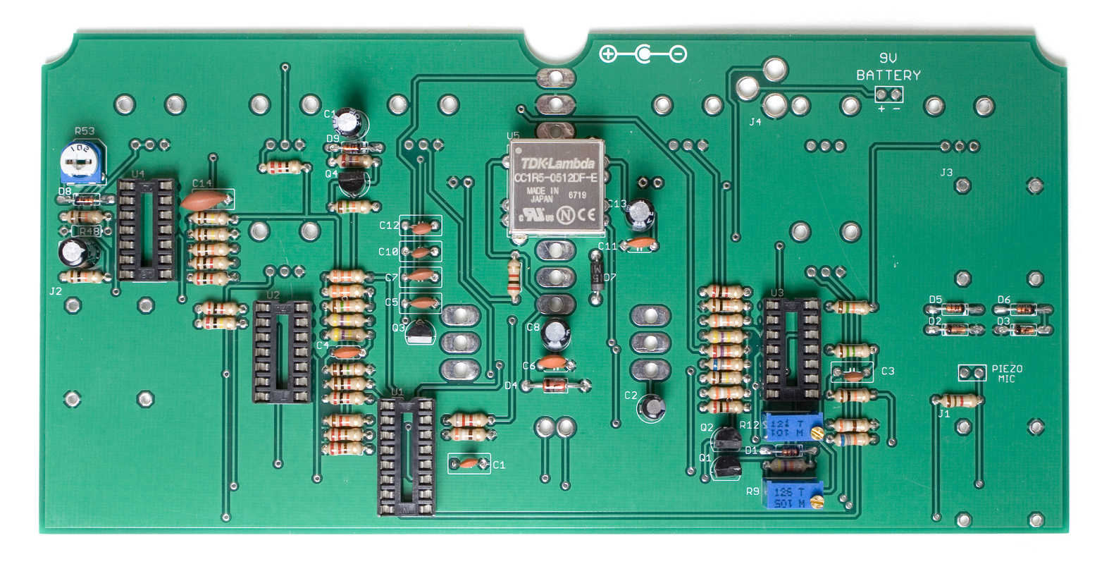
First up in the build are the diodes. These guys are polarized, so make sure when you are populating them, that you align the stripe on the diode with the stripe marking on the PCB. Once they are all in place, carefully flip your project over and solder everything in place, clipping any excess leads.
Resistors
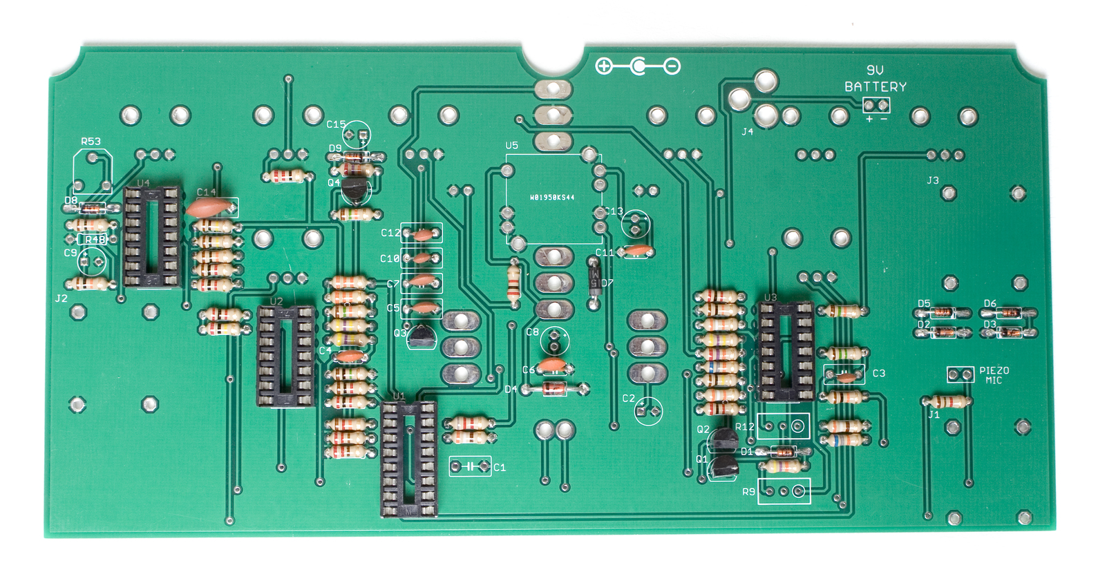
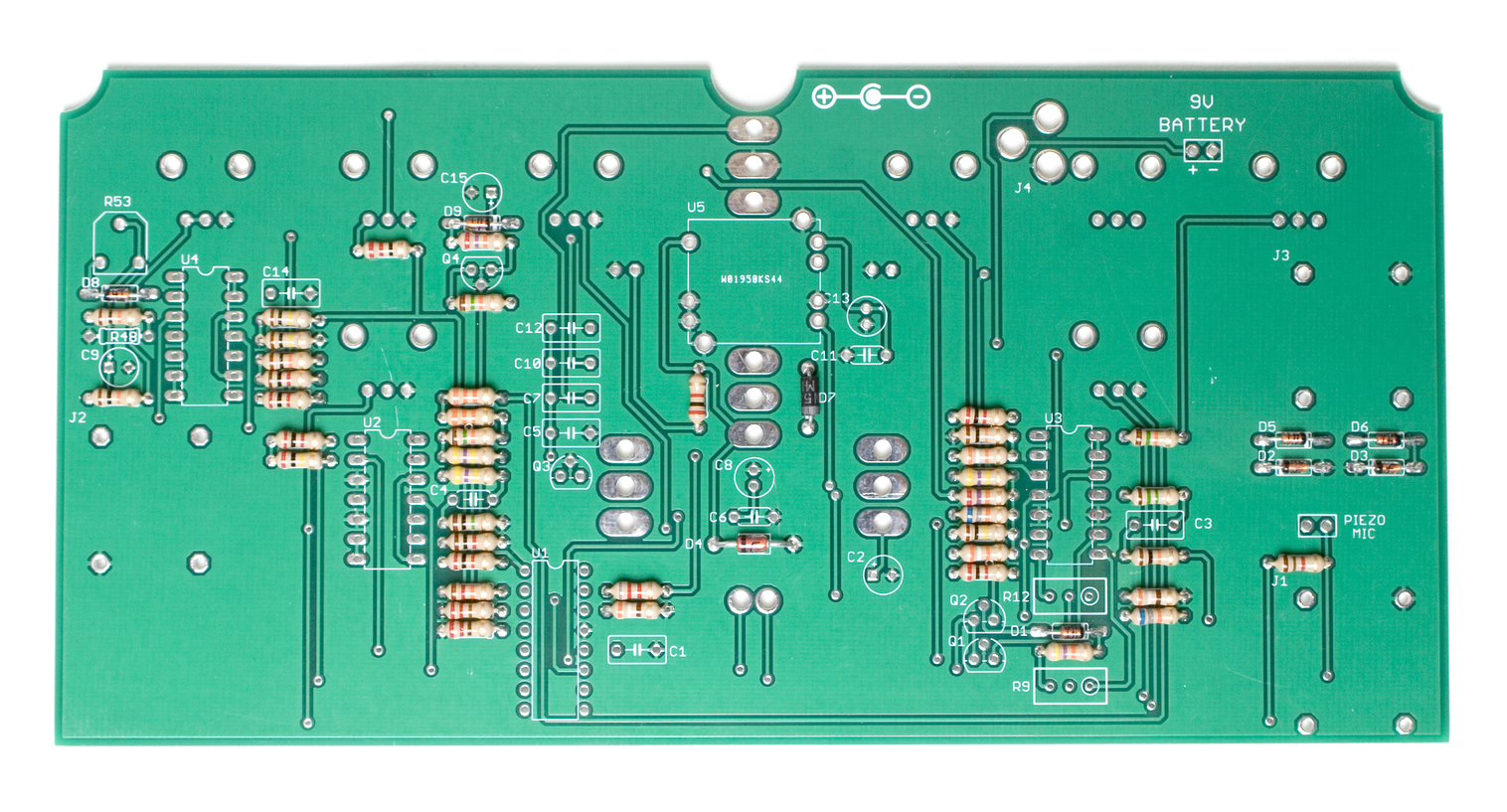 Next up are the resistors. These are not polarized, but it is recommended to populate them so that all the tolerance bands (usually a gold stripe) are facing the same way. This will make reading the values easier if you need to do any troubleshooting later. Populate the resistors according to the Bill of Materials, and then carefully flip your project over and solder them in place, clipping the excess leads.
Transistors
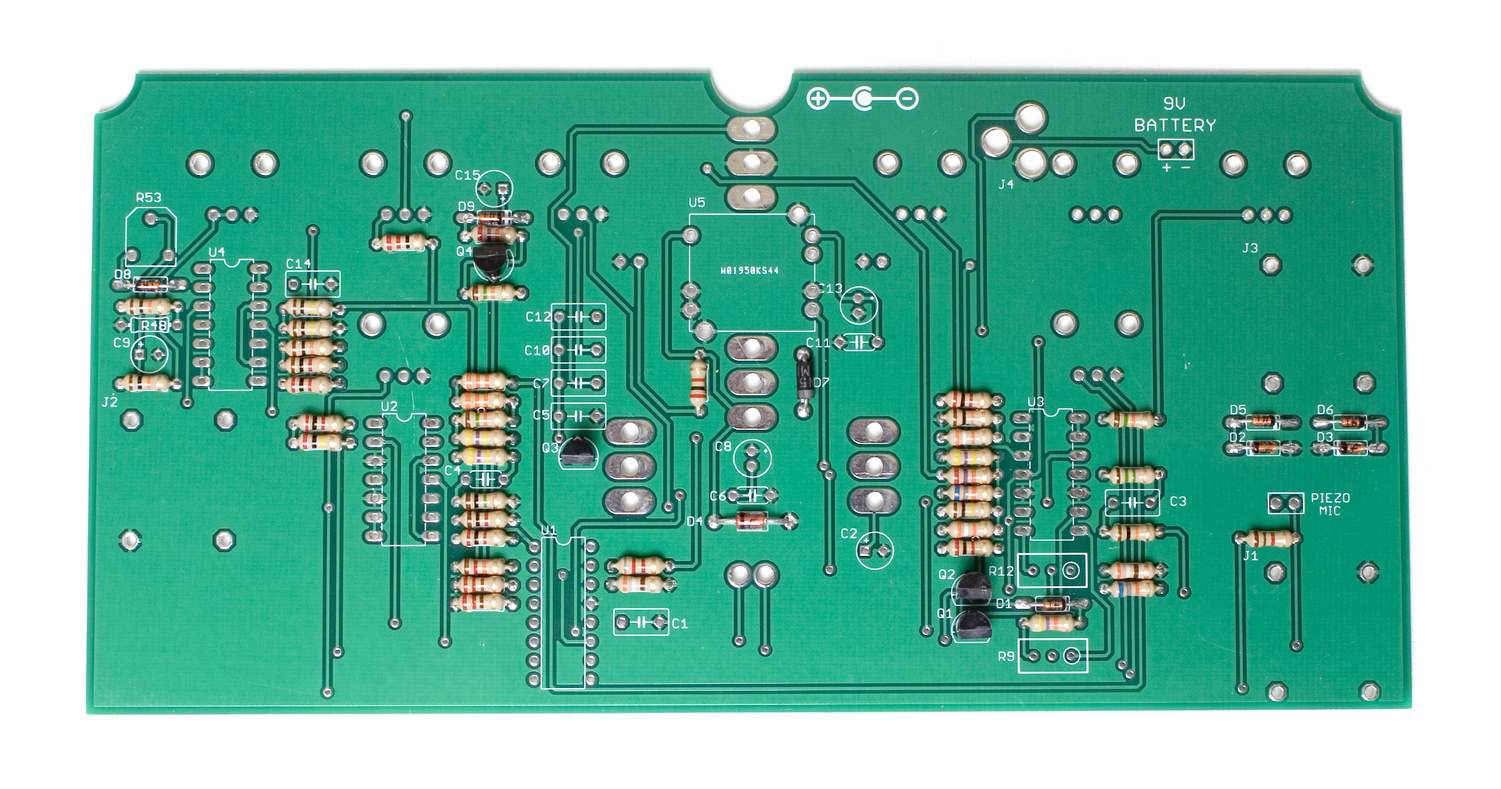 Now we can populate the transistors. When populating these, take care to align the flat side of each transistor with the indicated flat side on the PCB. Once everything is situated in the board, carefully flip over your project and solder everything in place, clipping the excess leads.
IC Sockets
 Next up are the IC sockets. Populate these according to the BOM, making sure to line up the half moon notch that is on one end of the socket with the same half moon notch on the PCB. Once they are all populated, carefully flip your project over and solder everything in place. If you are having trouble flipping the board over with the sockets in there, you can use a flat card, or piece of cardboard to help flip it over.
A trick to getting the sockets flat is to only solder one leg of each socket first, then go back and re-flow the joints while applying gentle pressure to the top of the socket.
Ceramic Capacitors
 Ceramic capacitors are not polarized, so when you are populating these, it doesn’t matter which direction they go. It is recommended to populate them in a way that the numbers on the side can be easily read, so that any troubleshooting that may need to be done later is easier.
When you have them all in the proper place, carefully flip your project over and solder everything in, clipping any excess leads.
Voltage Regulator
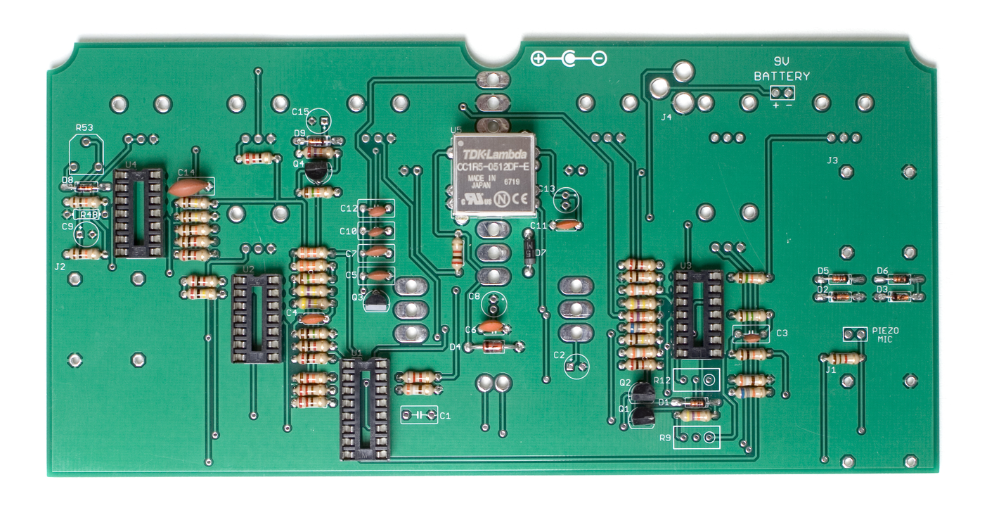 Next up, we are going to populate the -12v converter. Carefully line it up as shown above, and then solder it in place.’
Electrolytic Capacitors
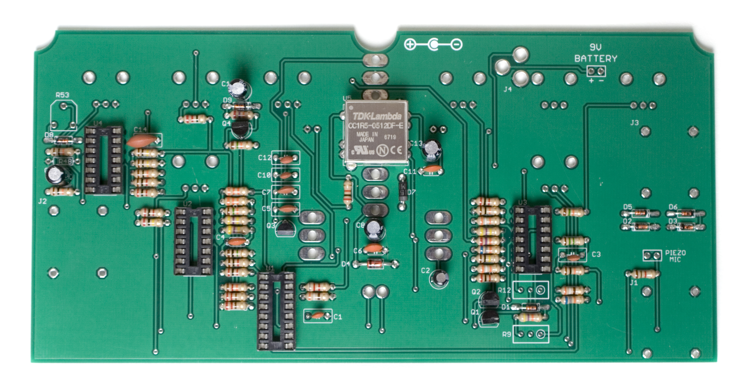 Now we can populate the electrolytic capacitors. These guys are polarized, so make sure to take care when populating them. Line up the longer lead of the capacitor with the hole in the PCB that has a ‘+’ next to it. When you have everything populated in the proper spots, carefully flip your project over and solder everything in place.
Trimmer Potentiometers
 Next are the trimmer potentiometers. There are two multi-turn trimmers and a single turn trimmer. When populating the single turn, make sure the flat side of it (with two legs) is lined up with the same marking on the PCB. For the multi-turn trimmers, align the side with the screw adjuster up with the side of the silkscreen that has a circle around the solder pad.
Once you have these populated, carefully flip your project over and solder everything in place.
ICs
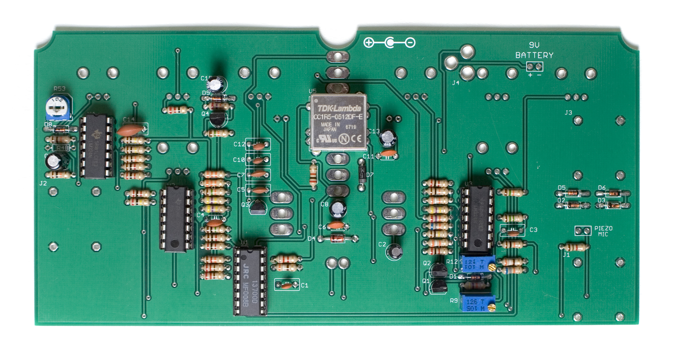 When inserting the ICs into their sockets, take care to ensure that the notch in the IC is lined up with the same notch in both the socket and the silkscreen on the PCB. You may need to slightly bend the leads of the ICs in to get them to fit good.
Case Prep
 We are almost ready to install the board into the case, so now is a good time to install the LED bezels in the case. Insert the bezels through the front of the case, and tighten the nuts down on the inside of the case. Be careful not to over-tighten these!
Power Entry
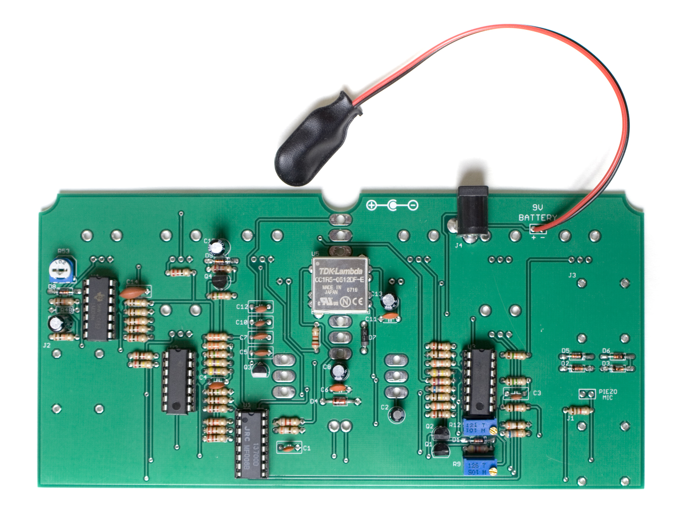 Next up, populate the DC jack and the 9v battery clip. Make sure when populating the DC jack, that it is as straight as possible, and lined up with the edge of the board.
When populating the 9v battery clip, make sure to solder the red wire in the solder pad that has a ‘+’ marking next to it.
1/4″ Jacks
 Now we can populate the 1/4″ mono jacks. Make sure that they are facing the proper way, with the opening facing away from the board. (its easier than you may think to get these backwards!) When you have them populated, carefully flip your project over and solder them in place. Make sure that you get these nice and flat, otherwise you may have issues fitting the project into your case!
Hardware
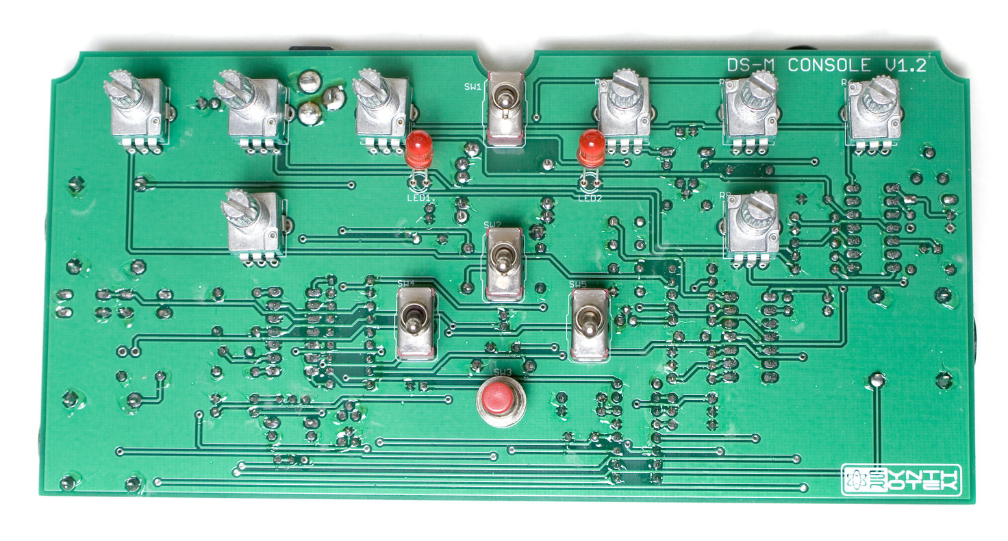 Next up, we are going to populate all the potentiometers, switches and LEDs. Carefully populate each component as per the Bill of Materials. Double check that the potentiometers are in their proper spots, as switching them out once the project is completed is extremely difficult!
LEDs are polarized components, and care must be taken when populating them. Make sure that the longer lead of the LED is on the LEFT when inserting them into their spots.
DO NOT SOLDER ANYTHING YET!
Casing the Space Drum
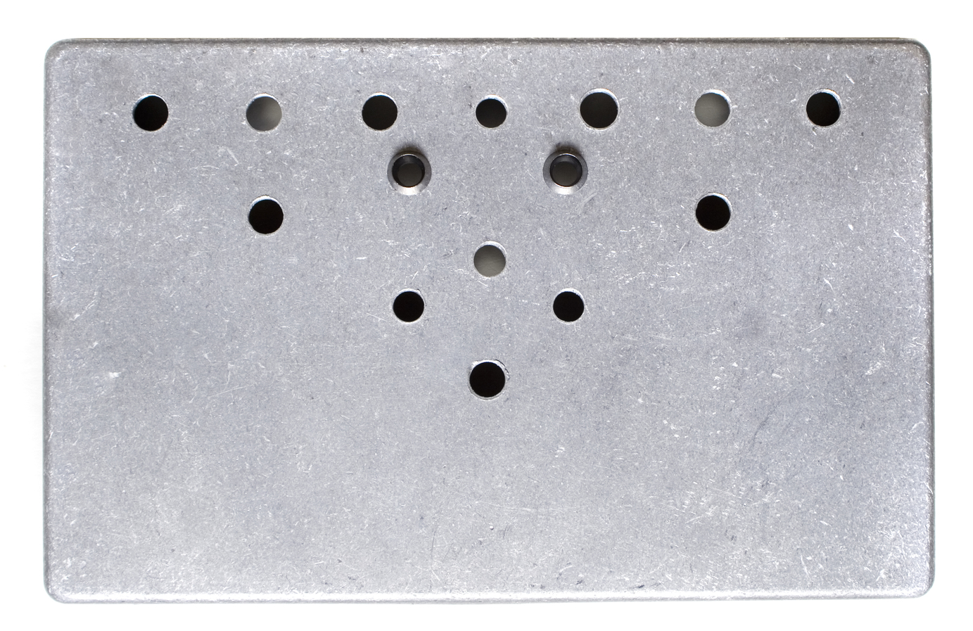
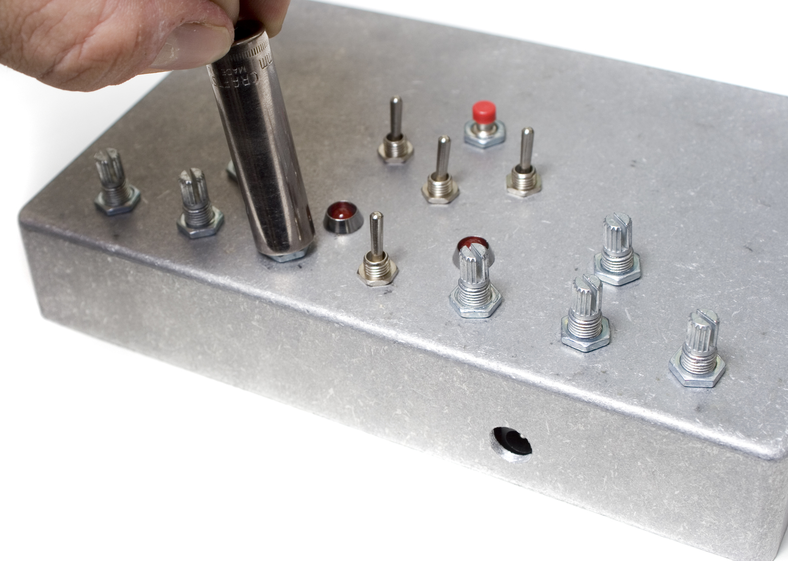
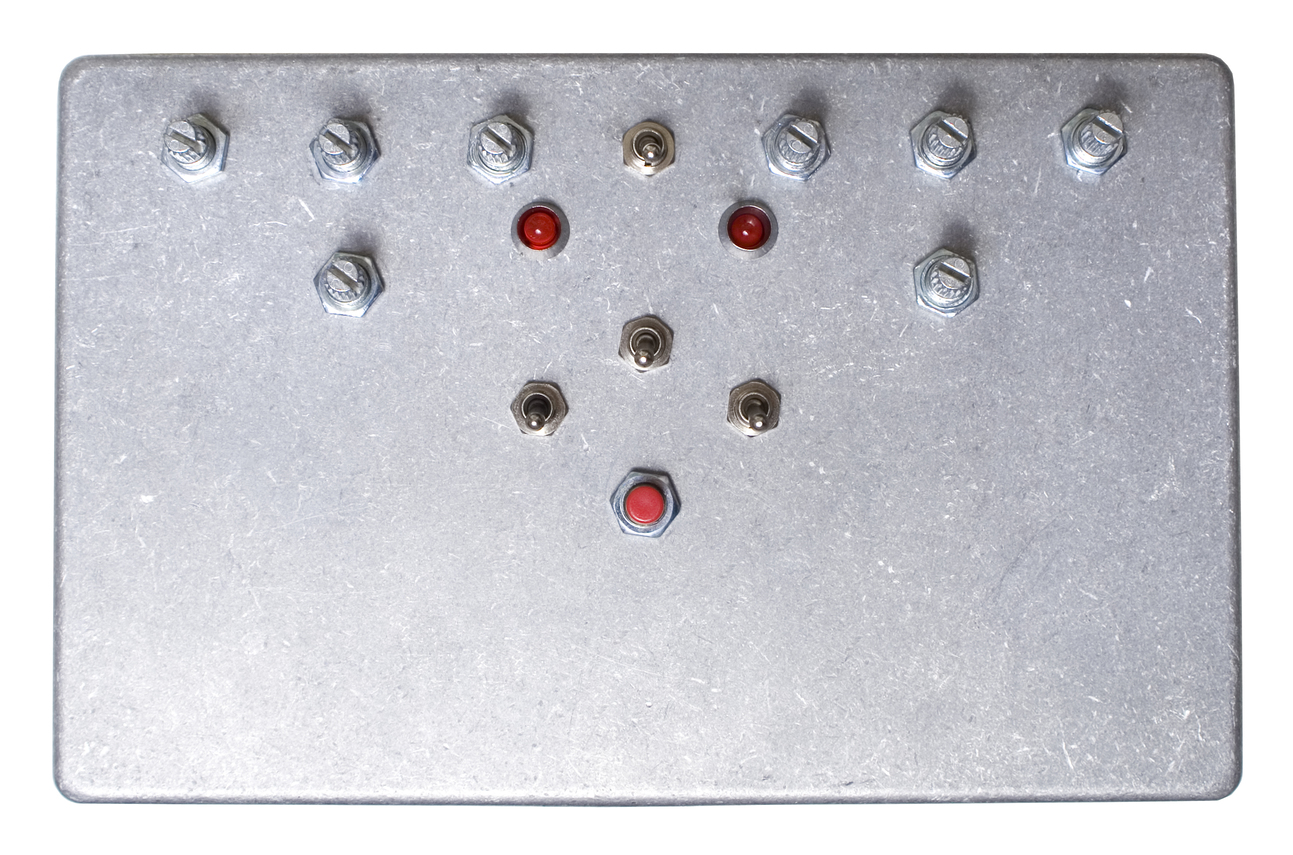 Next, we are going to install the PCB into the case. Carefully insert the PCB assembly into the case, making sure to line up all the components with their proper holes in the top of the case. You may need to hold it with one hand, and use a pen or small screwdriver to help align components with their holes as you insert them. Once everything is in and lined up, place the nuts on the components and use a socket to tighten them all down.
Its recommended to insert the nuts into the 1/4″ jacks on the side first, as this will hold the PCB assembly in the case while you tighten down all the rest of the nuts.
 Once everything is together and tight, double check all the alignments, and then solder everything in place.
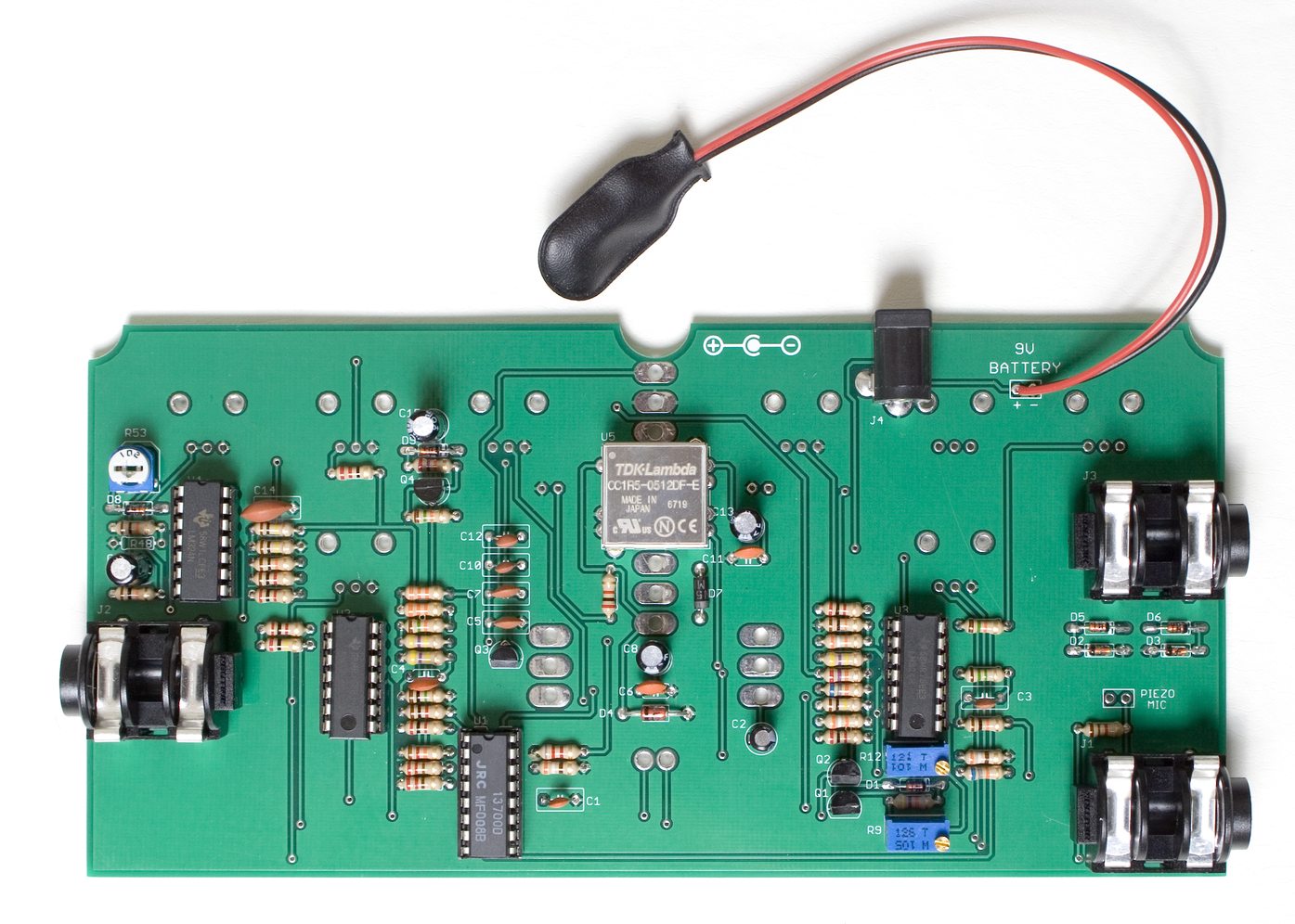
Piezo Mic
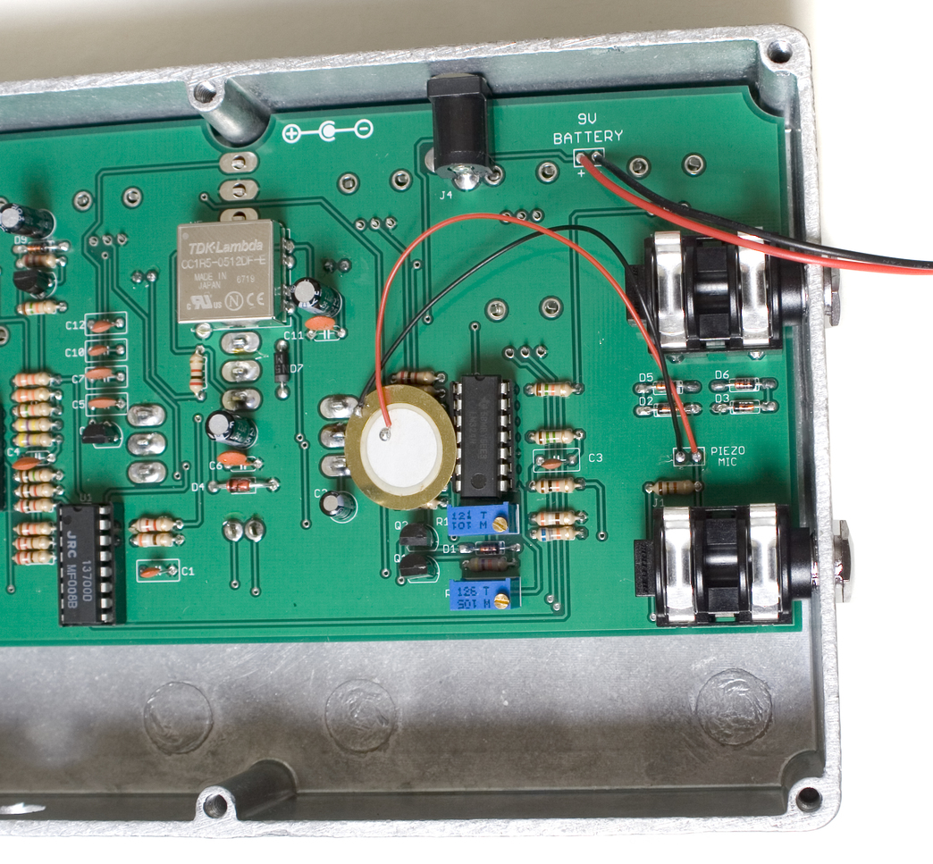 Next, solder the piezo mic into place as shown above. It doesn’t matter which solder pad the red or black wires go into.
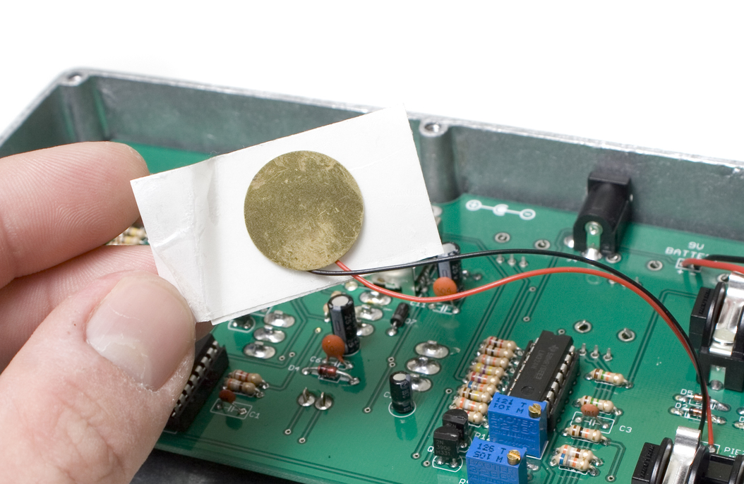 Grab your piece of tape, and affix it to the piezo as shown above. When it is placed on the case, you want the flat side of the piezo against the metal.
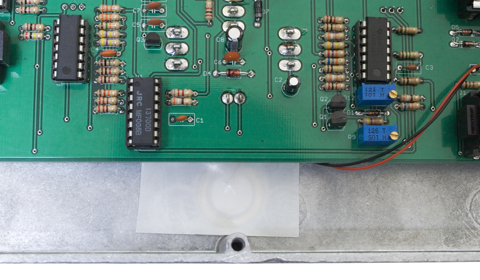 Firmly press the piezo and tape down, making sure that you have the piezo centered in the case. Be careful not to stretch the wires going from the piezo to the PCB.
Final Assembly
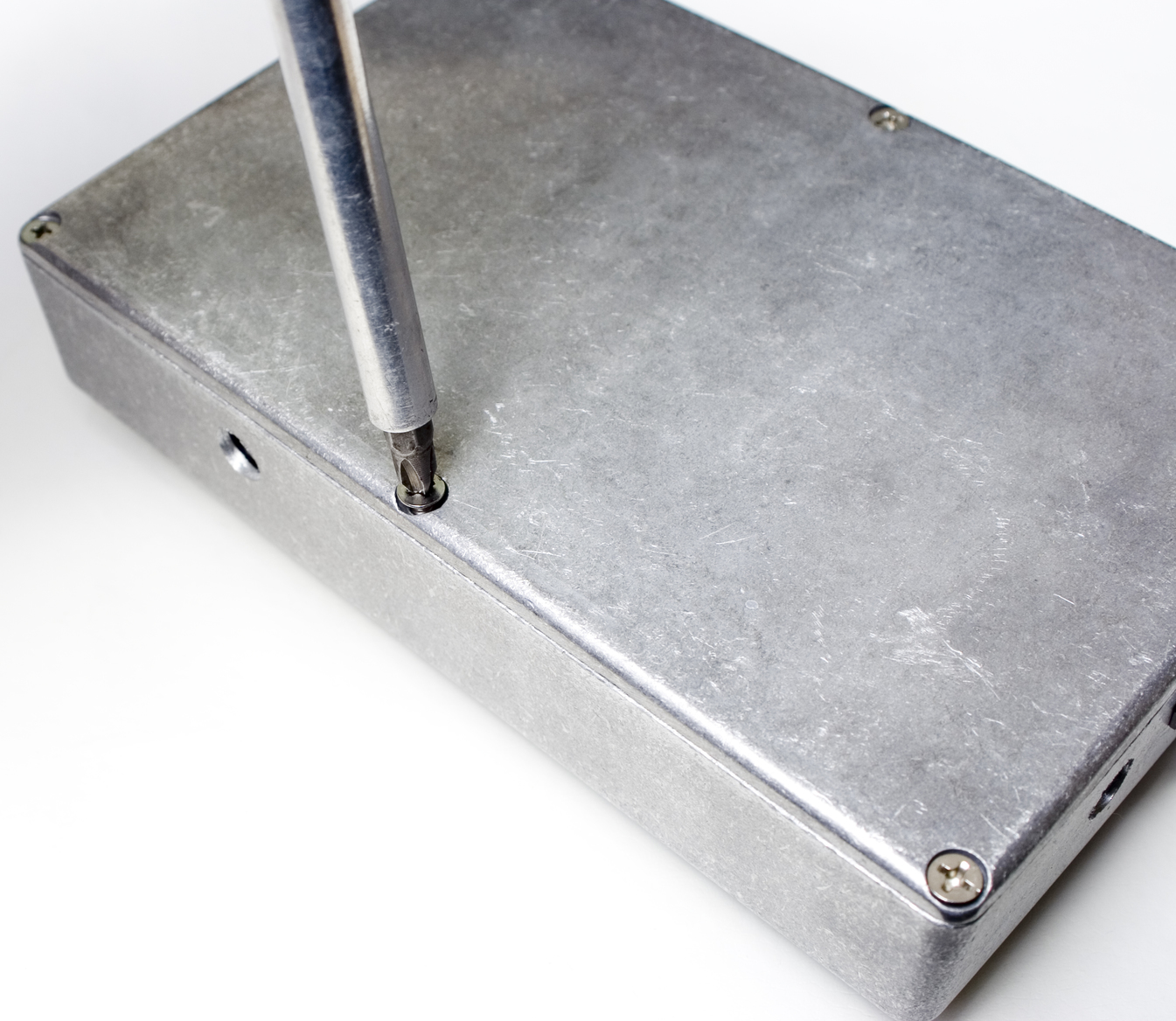 Finally, place the bottom of the case on your project, and use a phillips head screwdriver to tighten down all the screws.
When the bottom of the case is nice and tight, the last step is to install the knobs on all the pots.
 Congratulations! You have finished the Space Drum Synth build! Now that you have it built, you can follow the instructions below to fully test it, and make sure that it is functioning properly.
Thanks for choosing Synthrotek!