


Important Links
Product Page
Store Page
Assembly Instructions
Bill of Materials
Capacitor and Resistor Lookup Guide
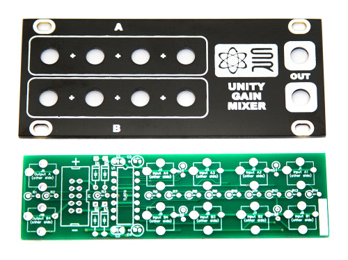
1U Unity Gain Mixer
Thank you for purchasing the Synthrotek Eurorack 1U Unity Gain Mixer Module kit! This is an intermediate build as it has many stand-up resistors and tight soldering. If you feel like you can handle it please proceed! If not, get some help from a friend with experience or purchase a fully completed unit.
These assembly instructions show the PulpLogic format version of the module, but the build order will be the same if you purchased the 1U Multiformat version.
ATTN: Please follow the BOM and these instructions and don’t populate from the PCB alone. Also sometimes we cannot get the exact pictured components, so please look over your parts and check the codes first. Lets begin!
DIODES
Start with the diodes as shown below, then turn over on a firm surface to solder, then clip your leads. Diodes are polarized components so you must match the black stripe on your diodes with the white stripe on the PCB silkscreen.
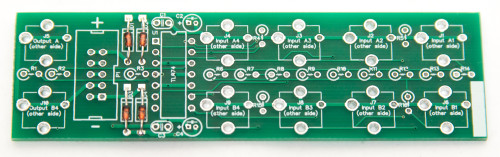
1U UNITY GAIN MIXER Diodes
IC SOCKETS
Place the IC Sockets by aligning the notch with the notch graphic on the PCB Silk Screen. Turn over on a flat surface and solder into place.
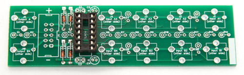
1U UNITY GAIN MIXER IC Socket
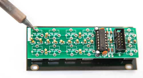
RESISTORS
There are quite a few resistors that need to be installed standing up. It is helpful to bend over one of the resistor leads first before populating each resistor. Solder and clip leads.
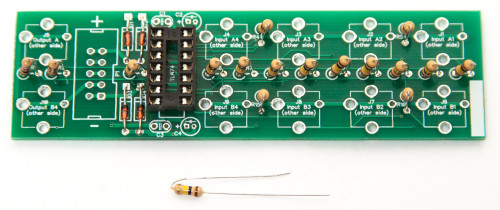
1U UNITY GAIN MIXER Resistors
CAPACITORS
Add the non-polarized capacitors as shown below. Next, make sure you orient the electrolytic capacitors in correctly. The longer lead needs to be inserted into the hole that has the “+” marking near it. Turn over to solder and clip leads.
1U UNITY GAIN MIXER Capacitors
10-PIN POWER HEADER & IC
Next add the 10-Pin Eurorack Power Connector in place by matching the key notch with the key indicator on the PCB silk screen. Turn over and solder on a flat surface. Then add the IC by aligning the notch of the IC with the notch on the header and pcb silkscreen.
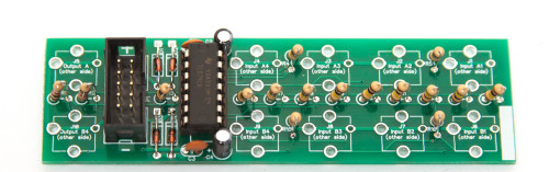
1U UNITY GAIN MIXER Power Header & IC
JACKS & PANEL
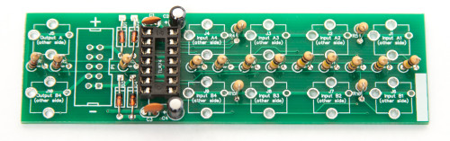
Now place the jacks on the other side of the pcb as shown below (do not solder just yet!).
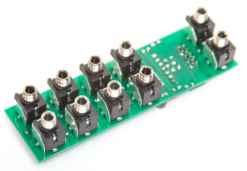
1U UNITY GAIN MIXER Jack Placement
Now marry the PCB and the Panel and fully tighten (not too tight) the jack nuts as shown below:
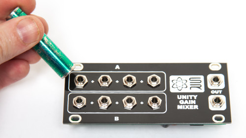
1U UNITY GAIN MIXER Jack Nuts
You can now solder the jacks in place. After you have soldered all of the jacks you are ready to test your module!
1U UNITY GAIN MIXER Final Soldering
TESTING PROCEDURE
The 1U UNITY GAIN MIXER has two independent sections (marked A & B) that are capable of mixing / summing AC signals (audio) and/or DC signals (gates, triggers, CV).
TESTING WITH AC
Start by plugging in an AC signal from the OUTPUT of an oscillator, sampler, percussion module, or any other module that outputs audio into the UNITY GAIN MIXER’s INPUT A section (top left of module). It is best to start with the jack on the far left side. Take a second AC signal and plug it into the next INPUT on the UNITY GAIN MIXER’s “A” section. Both signals should now be summed together, and you can monitor this by taking the “A” OUTPUT and running it into the INPUT on a mixer. Now test the other 2 available “A” INPUTS on the UNITY GAIN MIXER by either moving the two AC signals over or by plugging in two other AC signals from other sources. After verifying that all “A” INPUTS are summing AC signals correctly, repeat the same steps above for the “B” section to verify that it is also summing AC signals correctly.
TESTING WITH DC
Start by plugging in a CV signal from an envelope, LFO, sequencer, or a MIDI to CV module into the UNITY GAIN MIXER’s INPUT “A” section. It is best to start with the jack on the far left side. Take a second DC signal and plug it into the next INPUT on the UNITY GAIN MIXER’s “A” section. Both signals should now be summed together, and we can test this by running the “A” OUTPUT into the 1V/O INPUT on an oscillator and monitoring the frequency changes that the summed DC signals are causing. Now test the other 2 available “A” INPUTS on the UNITY GAIN MIXER by either moving the two DC signals over or by plugging in two other DC signals from other sources. After verifying that all “A” INPUTS are summing DC signals correctly, repeat the same steps above for the “B” section to verify that it is also summing DC signals correctly.
By now you should be able to confirm that all INPUTS and OUTPUTS are working correctly on the 1U UNITY GAIN MIXER and that both A & B sections are working correctly with both AC and DC signals.
If you have any questions or need help debugging, please first refer to our troubleshooting guide BY CLICKING HERE. If this gets you nowhere, please contact us by email for support. Thank you again for purchasing your kit from Synthrotek!
Mine works great. Different layout than the one pictured, but simple nd easy build. I cut off the spacers at the ends of the input jacks. That can’t be harmful, is it? Lastly a question on whether it should be functioning this way: If I have seven Audio Signals coming from a TR-808 Eurorack replica (https://www.youtube.com/watch?v=OgOwNm_sZew) and have them input into Jacks 2, 3, 4, &5 of “Column A” and 2, 3, &4 of “Column B” All seven are mixed into “Output A”, however when I input anything into “Input 1” of “Column B” everything on “Column B” becomes mixed down only to “Output B”. When I do this, “Output A” becomes twice as loud and “Output B” remains the same level. When Inputs 2, 3, &4 of Column B are used Output B” is the sum of only those three inputs and not all seven las “Output A” reacts.
Not complaining at all. I like it more this way as I happen to have a Drum-kit of Eurorack Modules that is exactly 8 pieces leaving me “Input 1” on “Column A” for a VCO.
Thanks,
Danny