


Important Links
Product Page
Store Page
Assembly Instructions
Bill of Materials
Quick Start Tutorial
Capacitor and Resistor Lookup Guide
Thank you for purchasing the Synthrotek AVR Programming Interface kit! It is very important to get all the components properly soldered into the PCB in the correct placement. If you feel like you can handle it, please proceed! If not, get some help from a friend with experience or purchase a fully completed unit.
Please build according to the BOM, and not these instructions or the pictures alone. Some components may have changed since these were written, or we may not be able to get the proper components in the pictures.
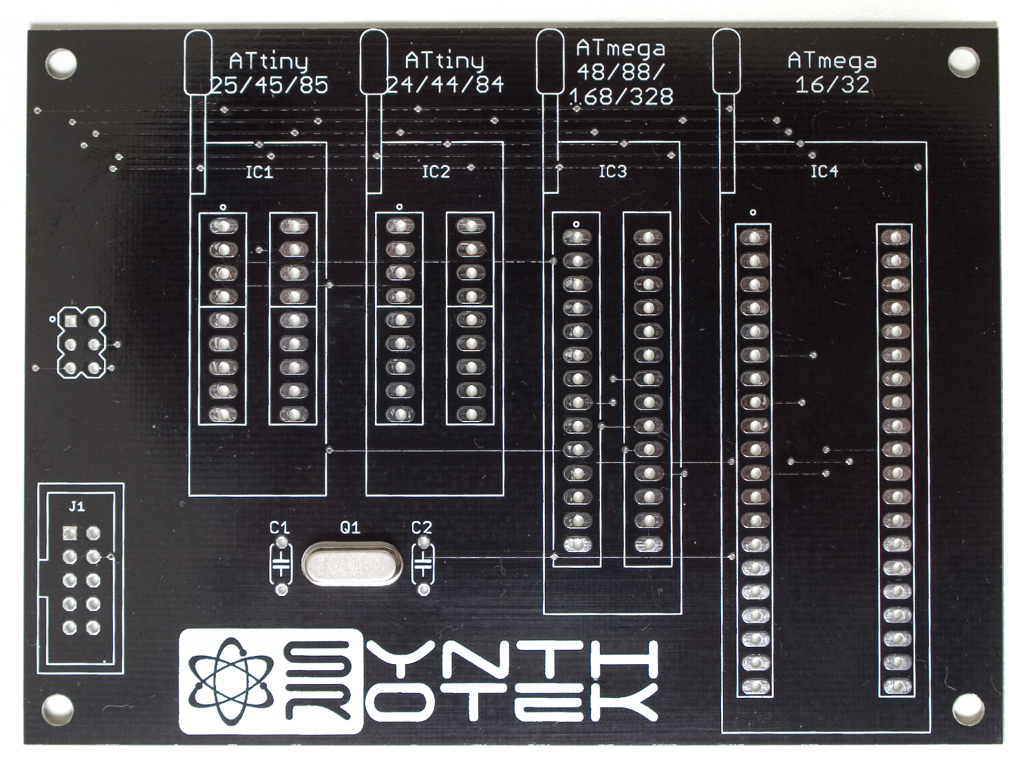
Crystal
The crystal in this build is optional, and will likely be determined by your project. Different applications of microcontrollers require different operation frequencies. We suggest socketing this if you plan on changing up what your doing a lot. The crystal is non-polar, so it doesn’t matter which way you insert it into the PCB, just stick it through the holes, and then flip your project over and solder it in place, clipping any excess leads.
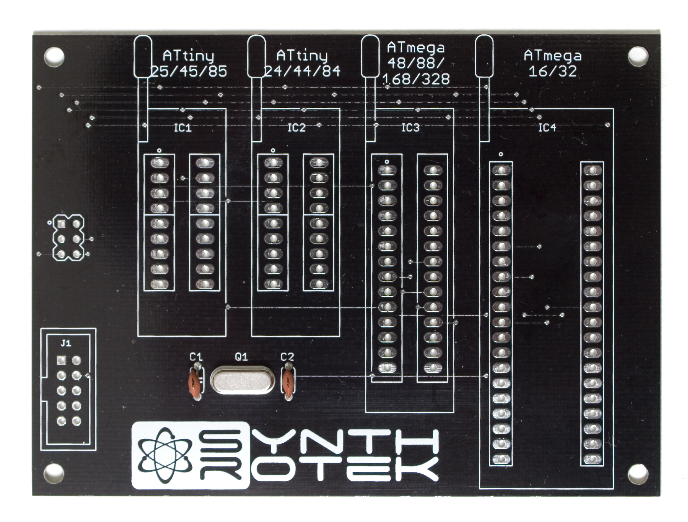
Ceramic Capacitors
Next up are the two 18pF ceramic capacitors. These are also not polarized, so insert them through the PCB. Then carefully flip over your project and solder them into place, clipping the excess leads. A trick to getting them sitting nice and straight is to only solder one leg of them in place, and then re-flow the solder, and adjust the capacitor. Then you can solder the remaining leg and clip the leads.
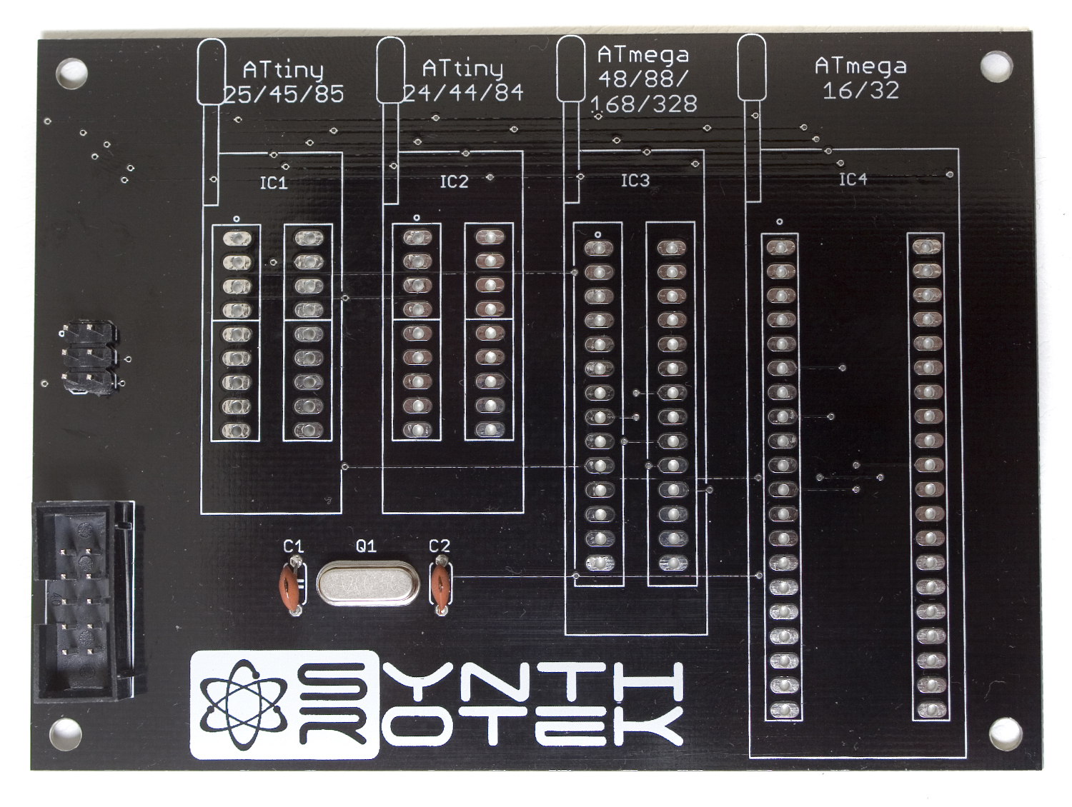
Programming Headers
Next up are the two programming headers. This is how you will interface your programmer with your microcontroller. You can hook your programmer into the ten pin header and then hook the six pin header to your projects ISP header, or just plop a chip right in the ZIF socket.
When inserting the 10 pin shrouded header into the PCB, make sure to align the notch in the header with the notch indicator that is printed on the PCB. This will ensure that your programmer gets hooked up properly. Once you have both headers in, carefully flip over your project and solder everything in place.
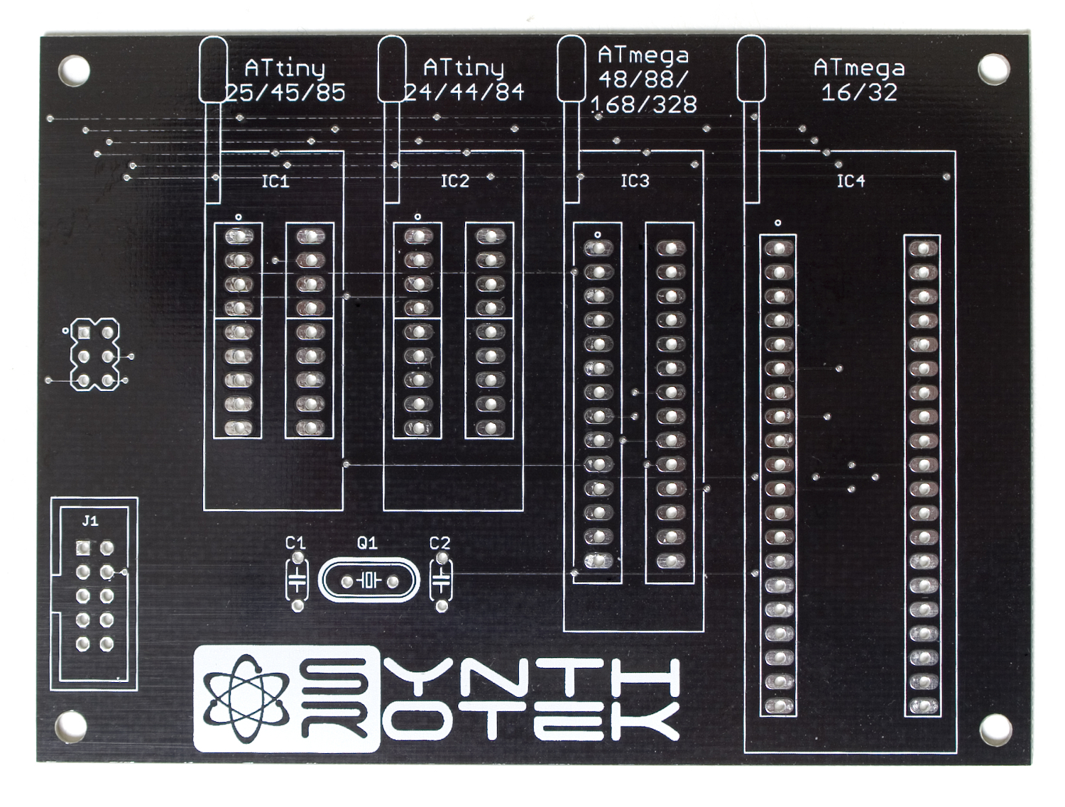
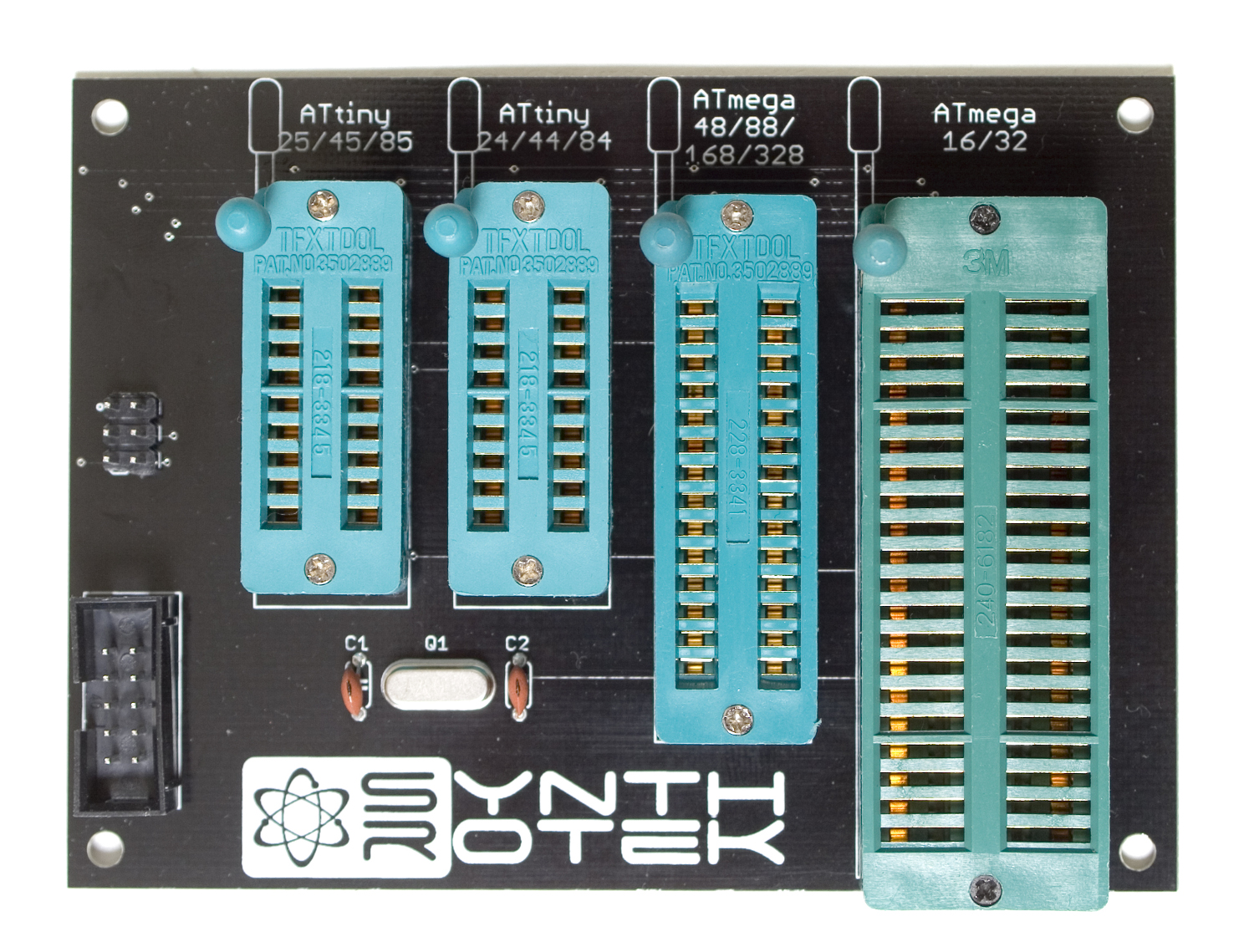
ZIF Sockets
Zero Insertion Force (ZIF) sockets are the next components to populate. The legs on these guys can move around a little bit, so we recommend making sure all the legs are nice and straight, and pushed ‘into’ the socket as much as possible. Start with the levers on the sockets in the up position, and when you insert it into the PCB, hold the socket to the PCB with one hand, and move the lever to the down position. This will push the legs on the bottom against the solder holes, and hold the socket in place easier. You can either solder them in one at a time, or you can solder them all at once, whichever you find to be easier. Once you have your sockets in the PCB, carefully flip your project over and solder everything in place.
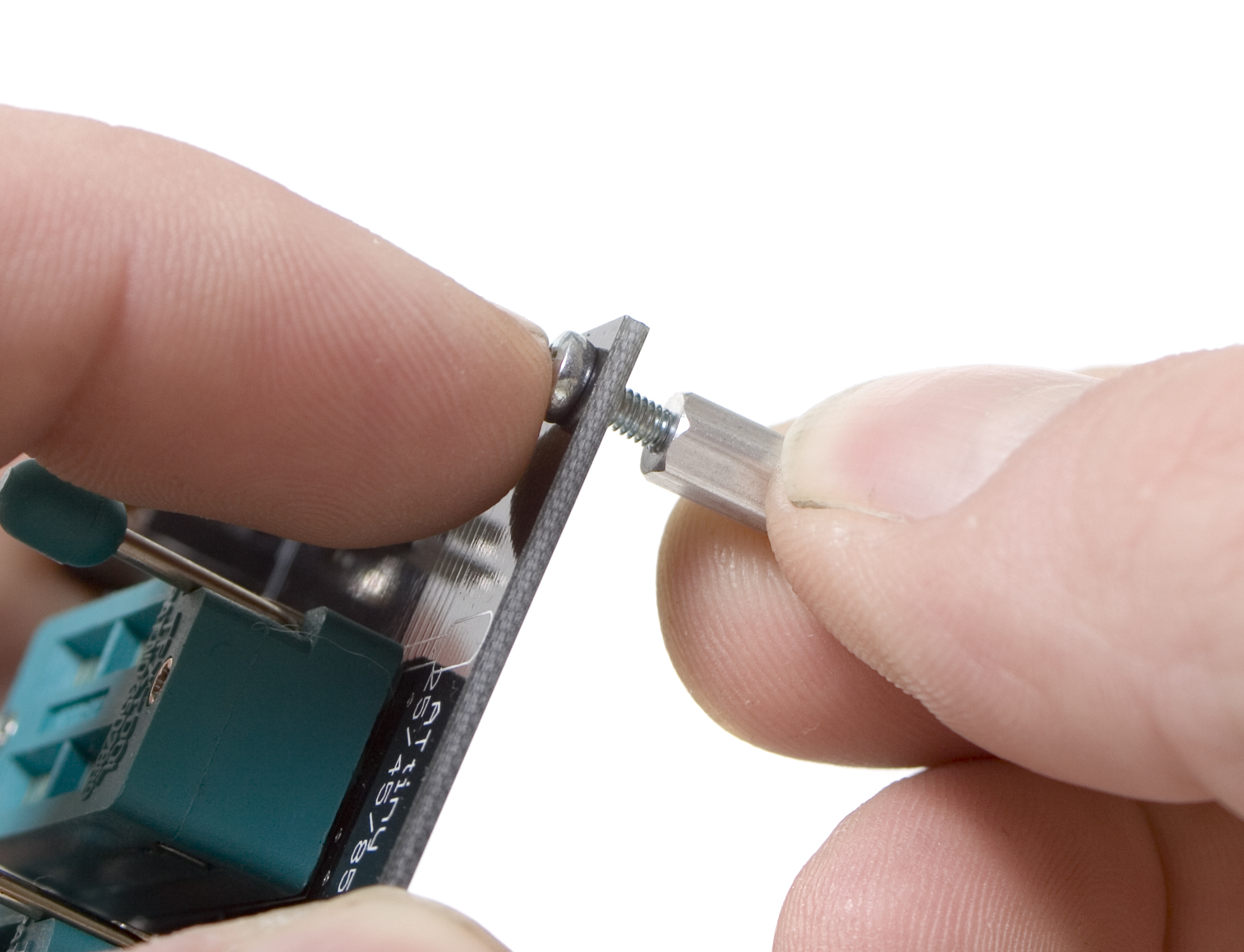
 Legs
Legs
The legs are completely optional on this project. Depending on how you want to use your AVR interface and how your workbench is set up, you may want to velcro it down, or use double stick tape, or even mount it straight to your desk with the provided wood screws and spacers. The included hex standoffs just make it easier to move around, and more importantly, they keep the metal pins of the sockets and headers off of the table, and anything that may be on it (like resistor clippings!).
Start by inserting the 2.5mm screw through the hole, and then spinning the hex standoff onto it. Once it is finger tight, you can come back with a screwdriver and tighten the screw down just a little bit more. Be careful not to over-tighten the screw or strip the hex standoff.
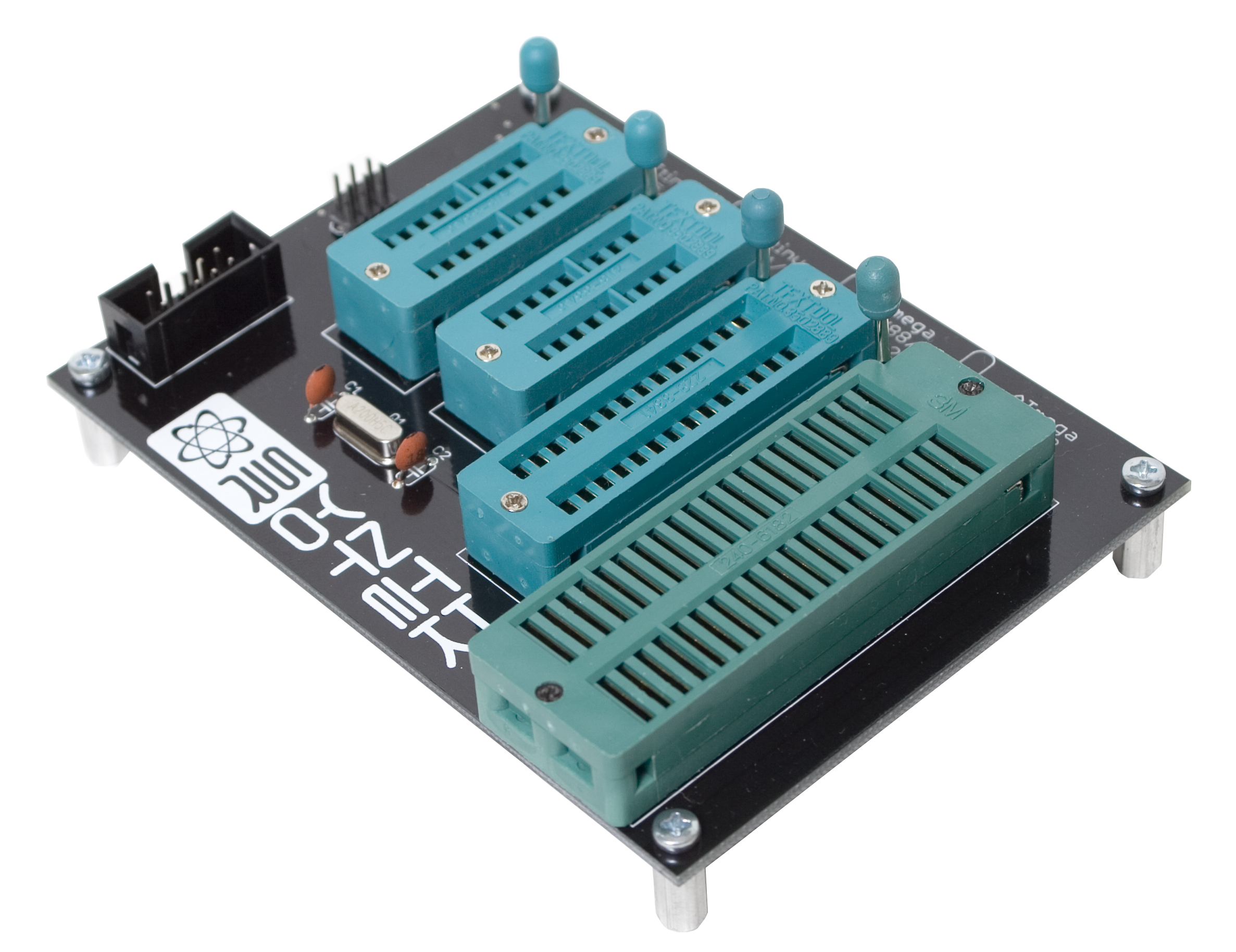
Completed Unit
Congratulations! You’ve completed your very own AVR Programming Interface! Keep on reading for a quick start guide on how to use it.
Quick Start Tutorial
In this quick start tutorial, we will walk you through how to use your AVR Programming Interface to program a microcontroller.
This guide is intended for people who are somewhat familiar with AVR programming, or if you just need to re-flash some code onto your chip/module. Please read through the AVR Programming Interface Manual for a more in-depth guide to AVR programming.
For the purpose of this tutorial, we will be using a USBasp programmer (with avrdude), and programming an ATmega88 chip with our ADSR code. If you would like to follow along, make sure you have everything you need before you begin:
- AVR Programming Interface
- At least one blank ATmega88
- USBasp
- A host computer with avrdude installed.
- The ADSR hex code.
Before we begin, please make sure you have avrdude installed on your machine. You can follow our guide to install it here.
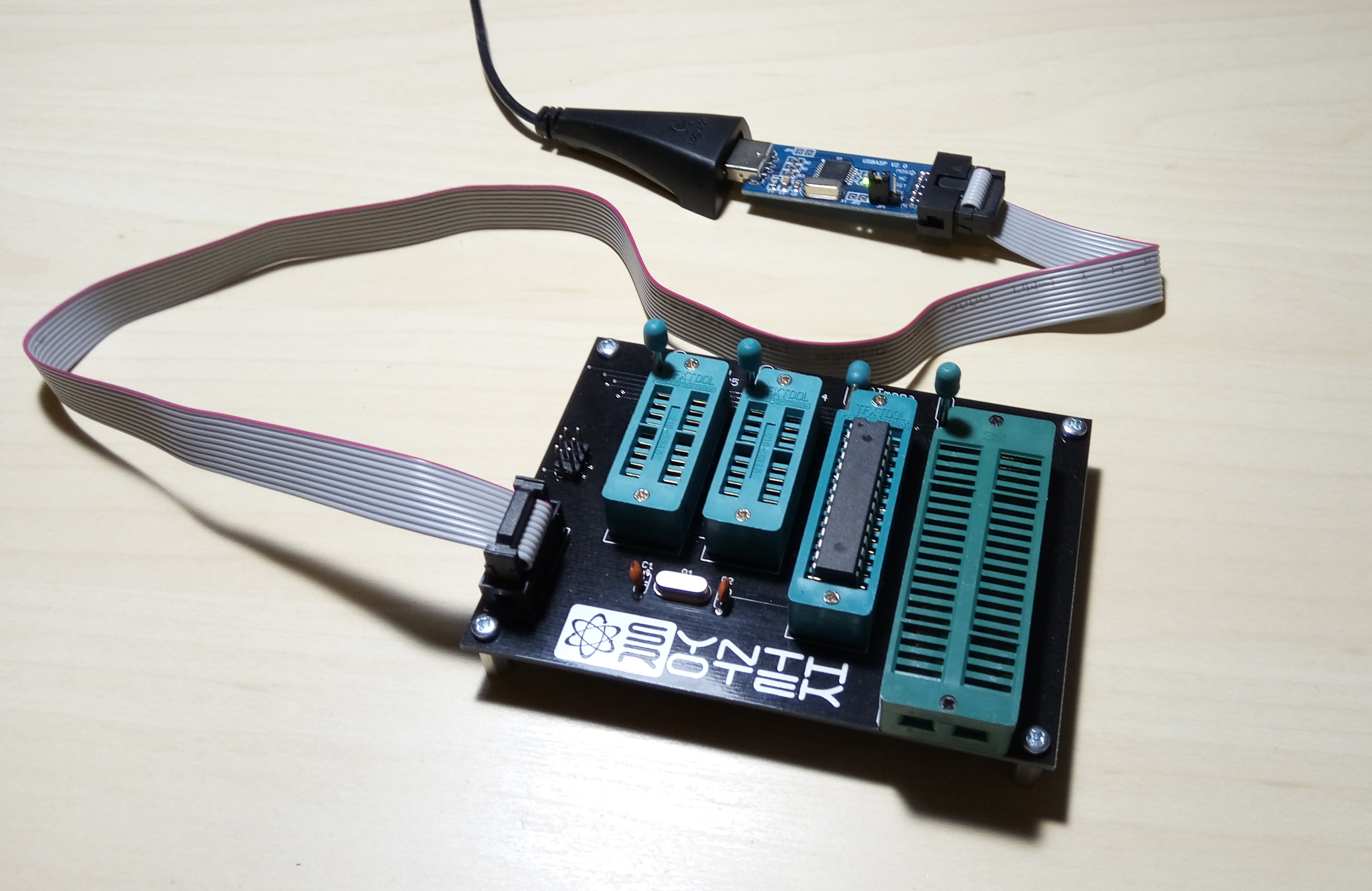
First up, plug in your USBasp to your computer via USB, and then attach the 10 pin connector to the AVR Programming Interface via the shrouded header.
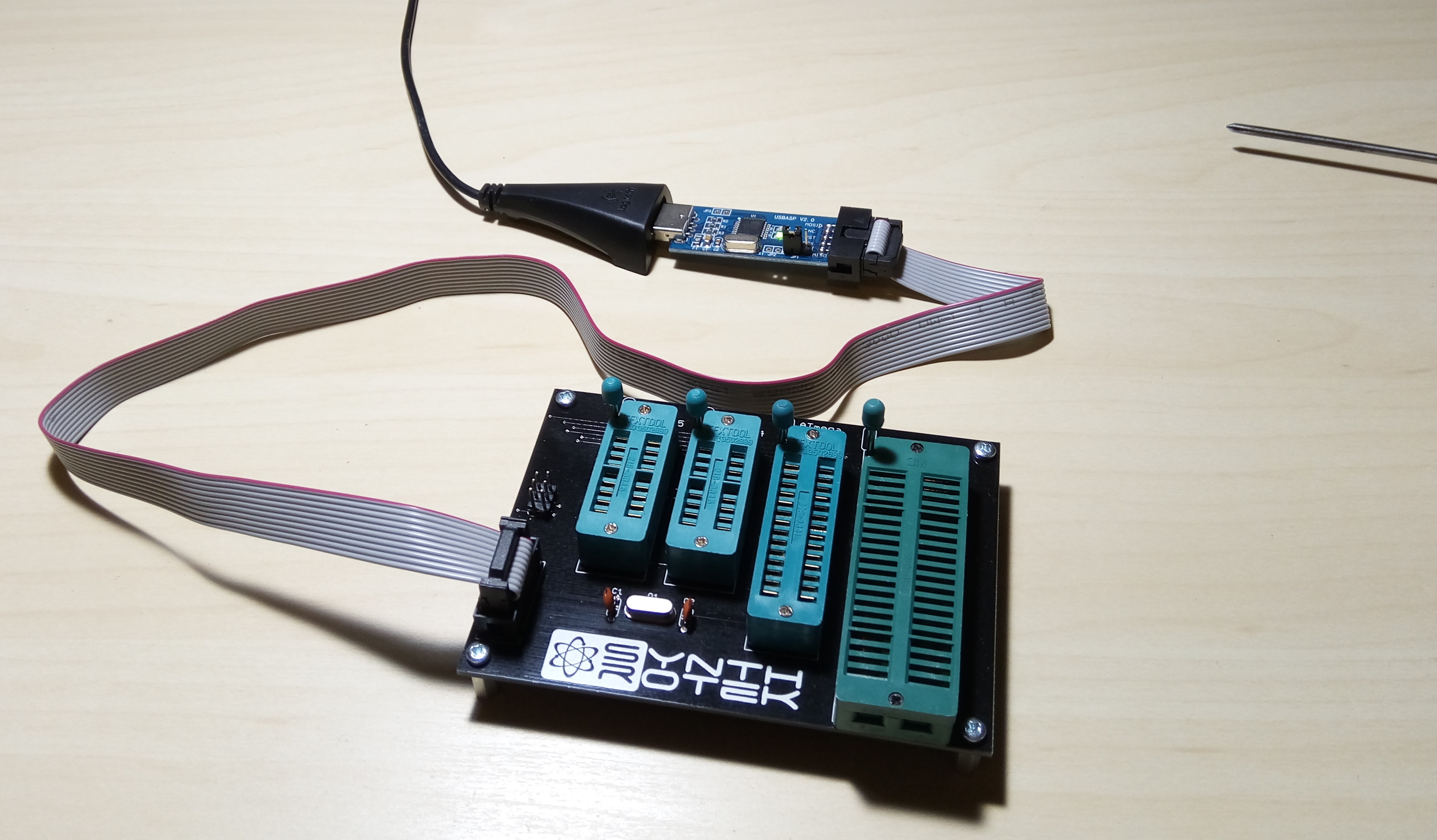
Next, Insert your ATmega88 into the third socket from the left, (with the lever in the up position), and then lock it in by pushing the lever down.
Next, we are going to use avrdude to program with fuse bits and load the .hex file.
Windows Instructions | Linux Instructions | Mac Instructions
Windows Instructions
insert instructions with screencaps here.
Linux Instructions
First up, open a terminal window (CTRL+ALT+T in ubuntu), and navigate into the directory where you downloaded your hex file.

Next, we need to program the three fuse bits to their appropriate values:
lfuse: 0xff
efuse: 0xf9
hfuse: 0xdc
To program these fuse bits, type the following into your terminal window, and keep an eye on the output for any errors that may pop up.
If it shows a warning about the sck period, thats fine. It will still work, but your usbasp may need a firmware update.
avrdude -c usbasp -p m88 -B 10 -u -U lfuse:w:0xff:m -u -U efuse:w:0xf9:m -u -U hfuse:w:0xdc:m

Next up, we are going to program the actual .hex file. To do so, type the following into your terminal, and hit enter:

Thats it! You should be able to pop the microcontroller into your ADSR module and turn it on.
You can also follow the above section to program any intel hex formatted file (ends in .hex) to any chip that our AVR Programming Interface supports. All you would need to do is find out the correct fuse bits for your project and then replace the values above with your values.