


Important Links
Product Page
Store Page
Assembly Instructions
Bill of Materials
Schematic
Capacitor & Resistor Lookup Guide
Eurorack EITHER-OR Module Assembly Instructions
BOM LAYOUT:
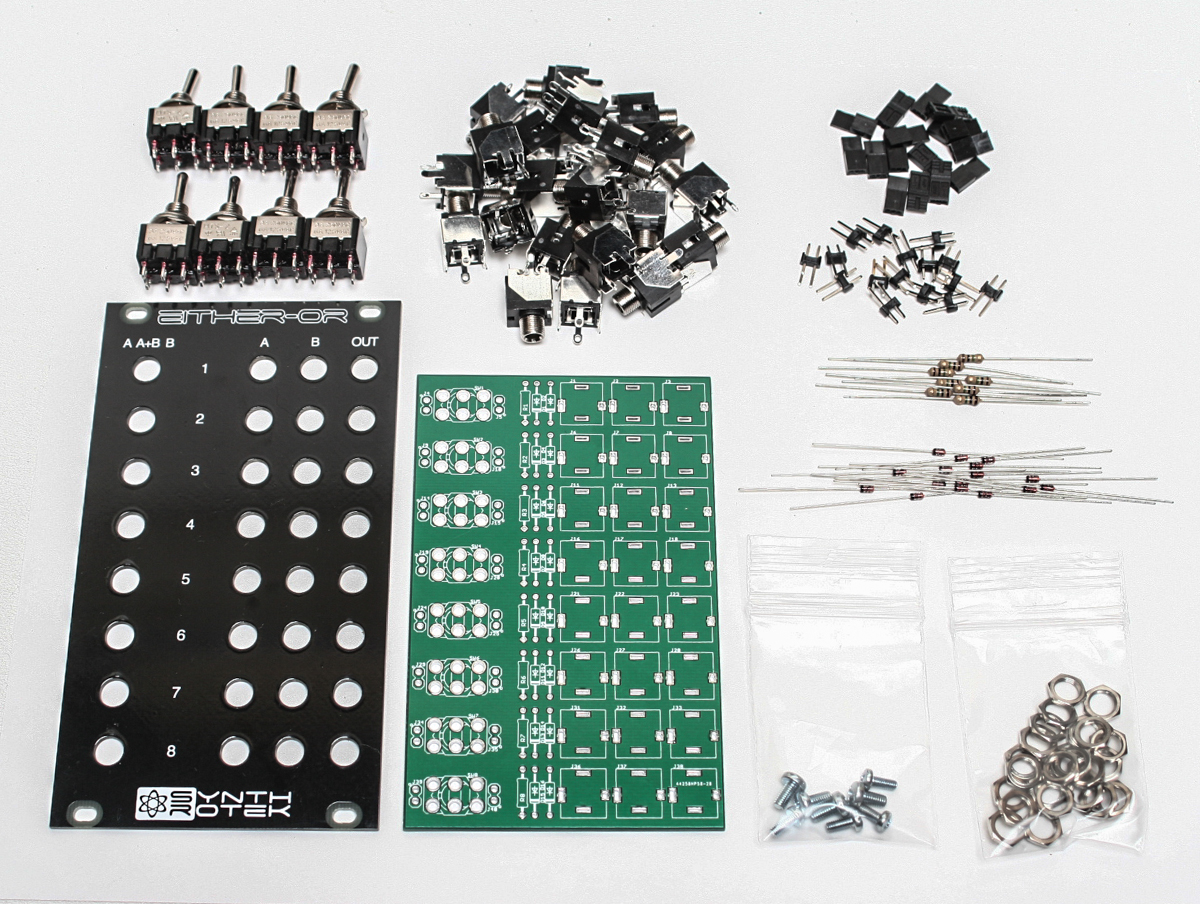
Either-OR Components
If you’ve received your parts and ready to build, the first thing you should do is to check to make sure you have all the parts. Check your kit against the Either-OR BOM, If you’re missing anything we’ll send it to you free of charge and apologize a bunch.
Soldering the Components
Attention: Changes may occur after the Assembly Instructions are created and the photos may not reflect those changes. Always use the BOM to verify the placement of components.
Resistors and Diodes:
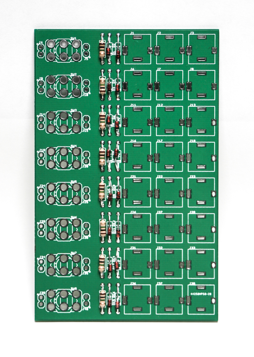
Either-OR Resistors and Diodes
First solder all the resistors and diodes into place. Ensure that the line on the diode matches with the line on the PCB silkscreen. Resistors are not polar sensitive so you may install them in any orientation.
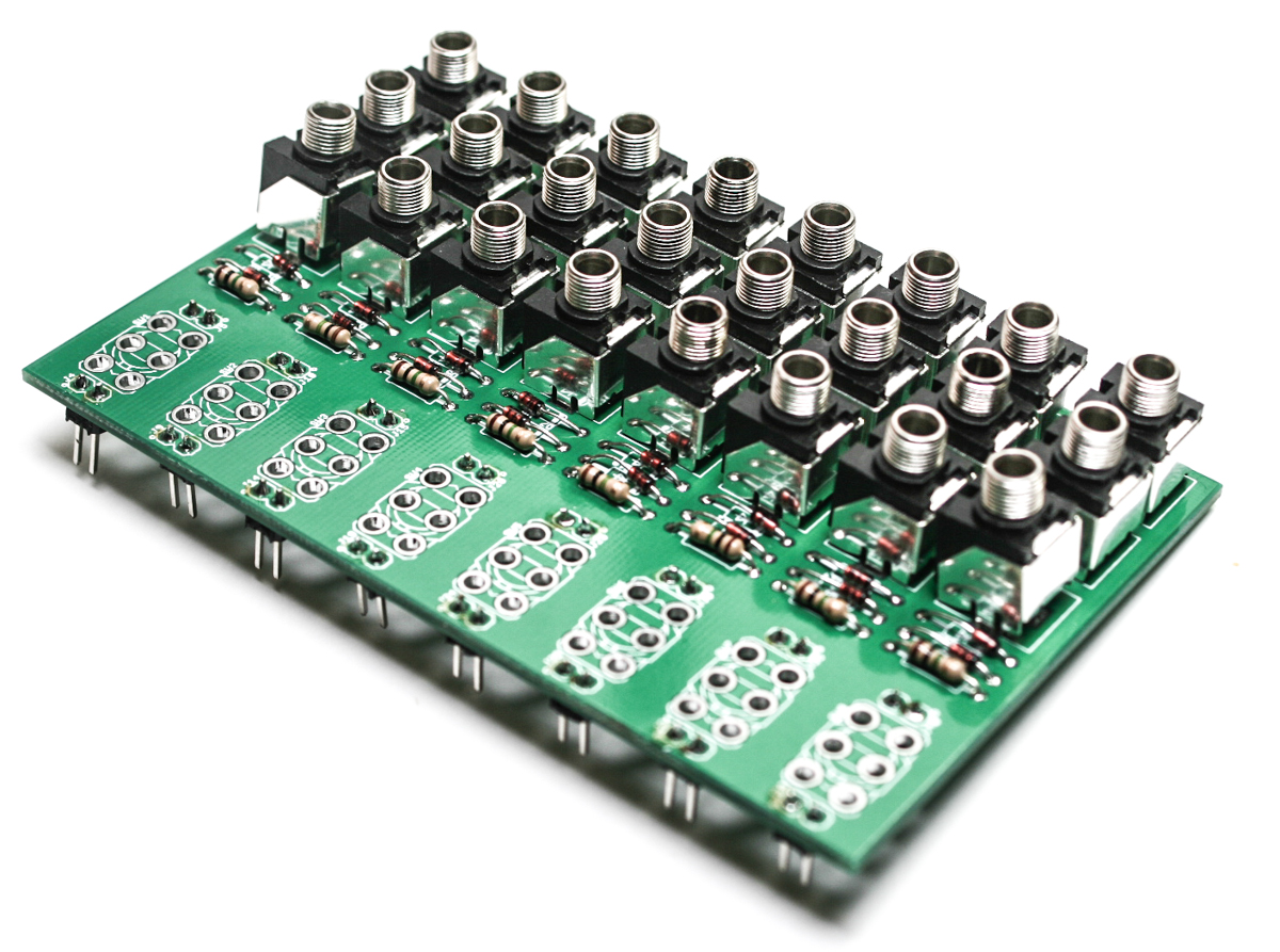
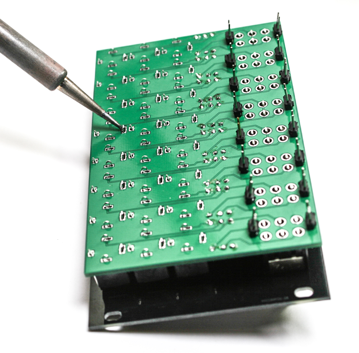
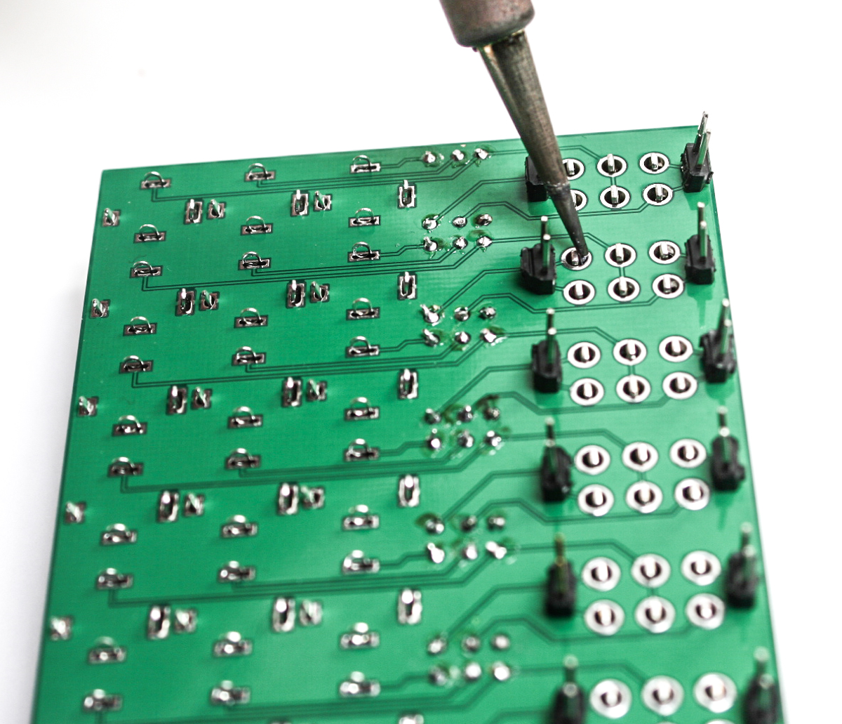
2-Pin Headers
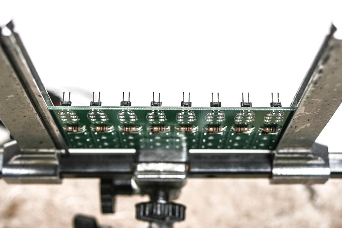
Either-OR 2-pin headers
Next, add all of the 2-pin headers on the opposite side the PCB. Insert the shorter end into the PCB. This is possibly the most tricky part of the build. A pan-a-vice or other brand tool will really help here. You need to set the headers in the PCB while being able to solder from the bottom. Solder them in place at this time.
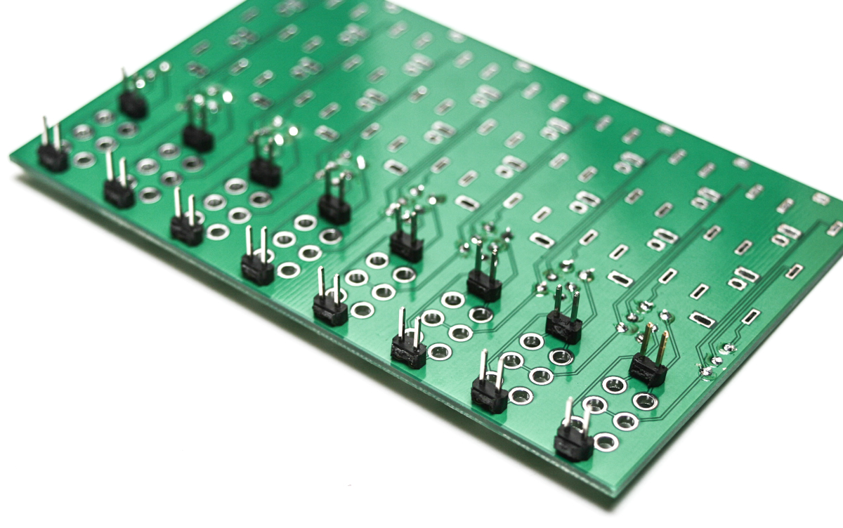
Either-OR 2-Pin Headers
Jacks & Switches
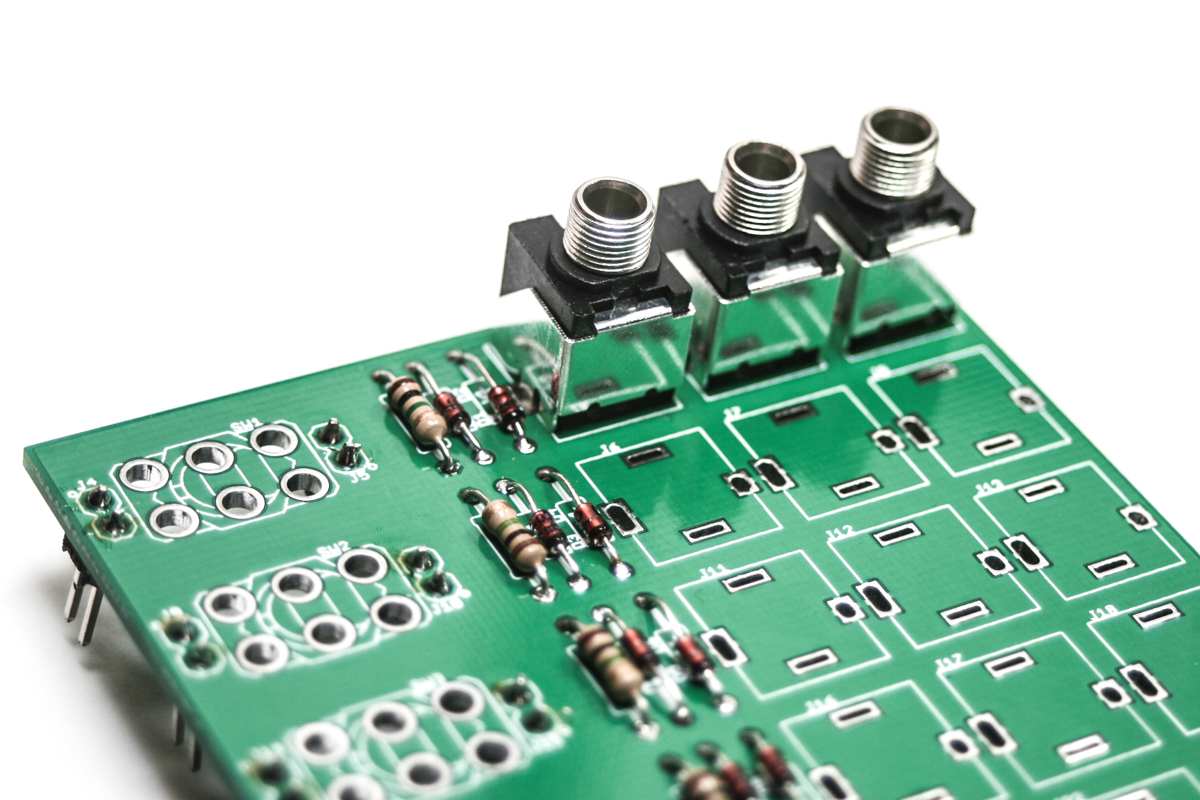
Either-OR Jack Placement
Start adding the jacks to the PCB as seen in the above photo.
Either-OR Jack Placement
Attach, BUT DO NOT SOLDER YET, all of the jacks in place. Next, move onto the switches.
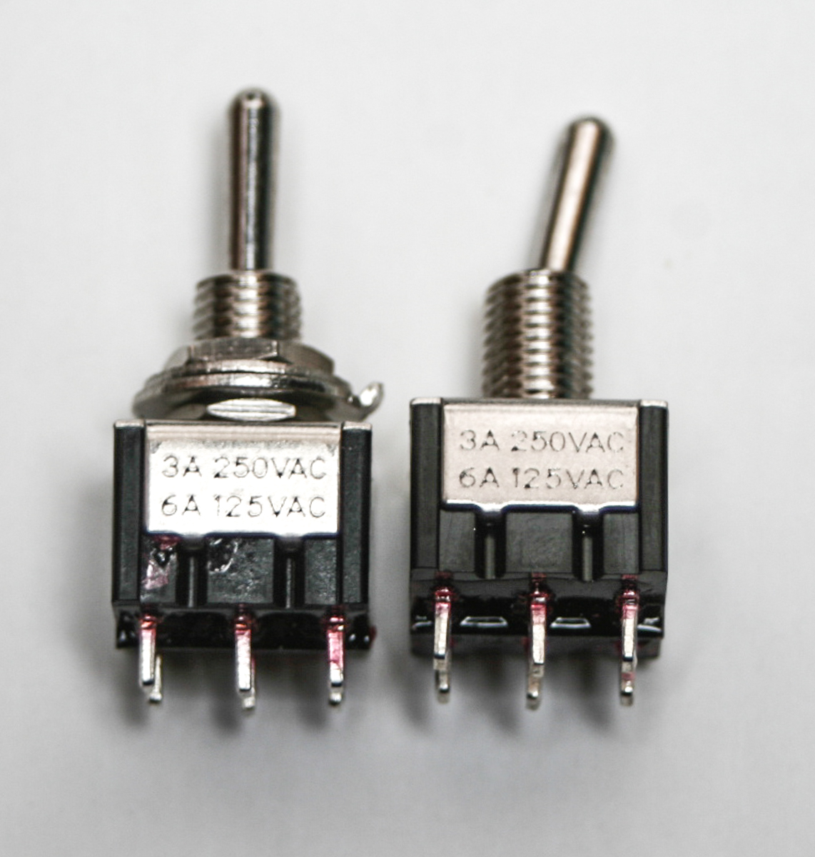
Remove all nuts and washers
Please remove all of the washers and nuts from the switches prior to placing the panel on the project. You will just need one nut per switch and this is applied after the panel is placed.
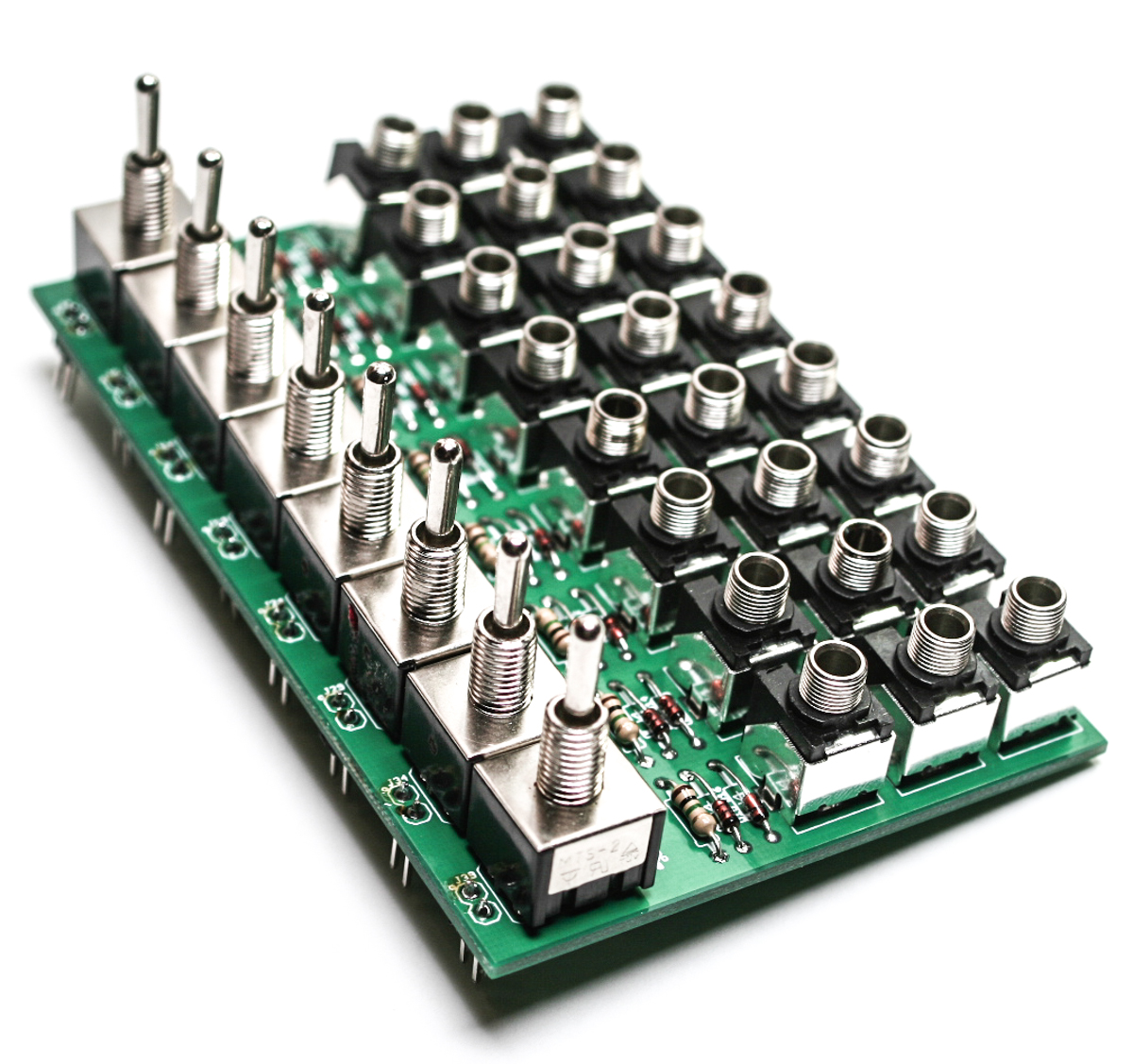
Either-OR Switches
Insert all 8 switches in the PCB, do not worry about which way to put them in, they will work either way. Again DO NOT SOLDER them at this point.
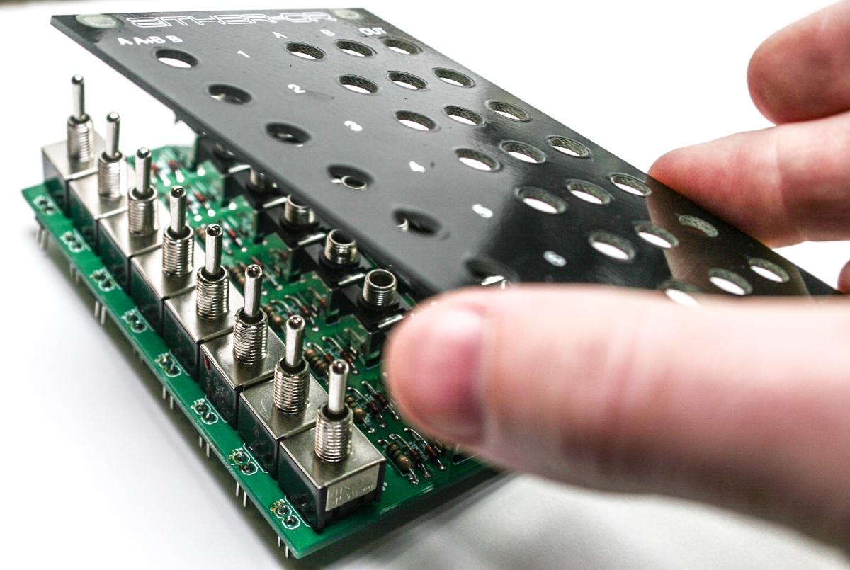
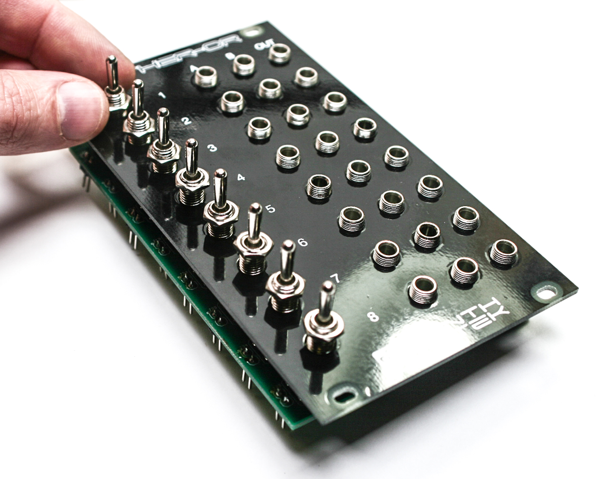
Either-Or Panel Placement
Carefully take the panel and lay it over the components so that the components poke through the panel’s holes.
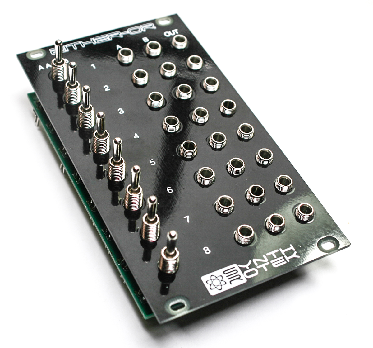
Either-OR Panel Placed
Press down the panel so that it fits over all of the components as seen above.
Placing Switch Nuts
Add the Switch Nuts and tighten down fully, but gently.
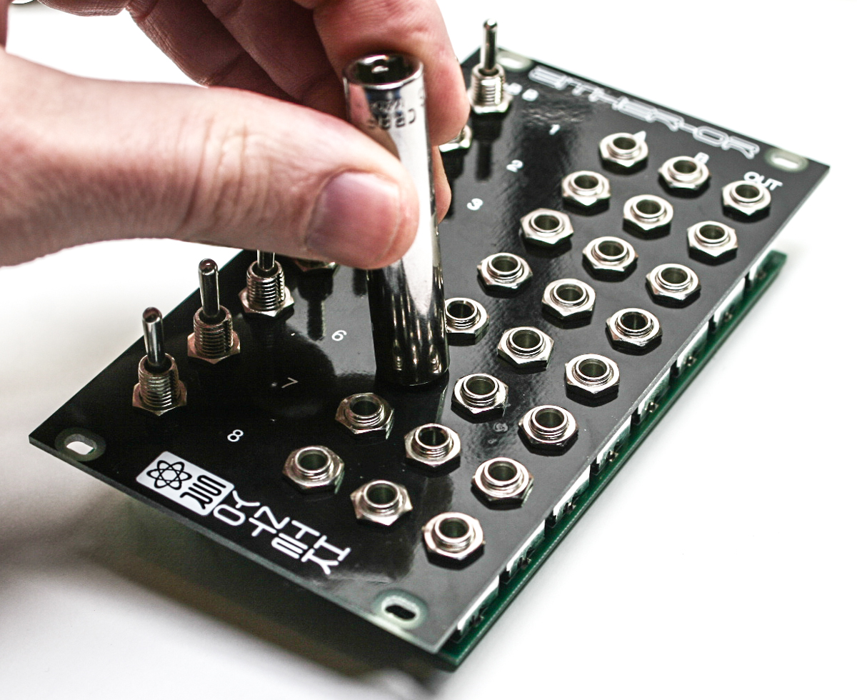
Tighten Jack Nuts
Next, add and tighten down the jack nuts fully, but gently.
Soldering Jacks
Gently turn over the module and solder down the jacks and switches.
Switch Soldering
Jumpers
Now add the jumpers either to one pin, or both (connecting both pins) to achieve the desired result (Either a ‘mute’ or an ‘OR Combiner’)
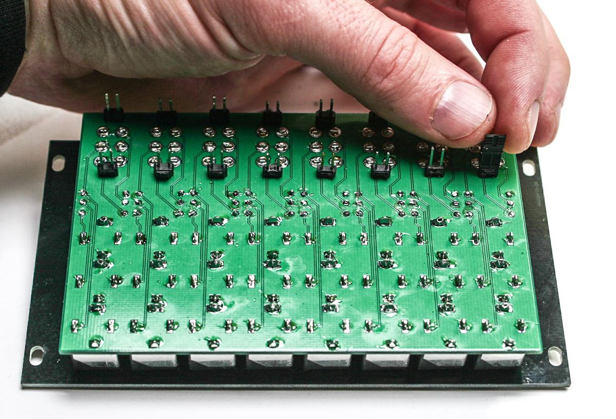
Adding Jumpers
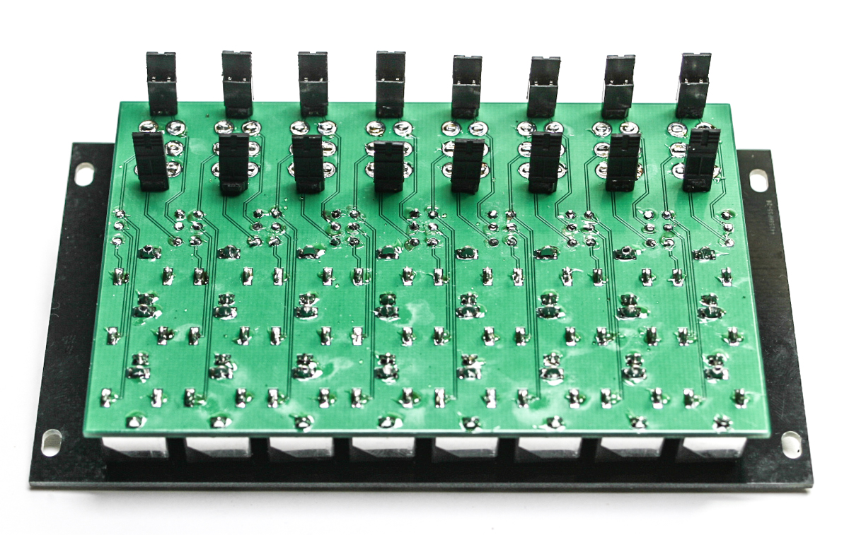
Either-OR Jumpers
After placing the jumpers, the project should be done and ready for testing and use. Congrats!
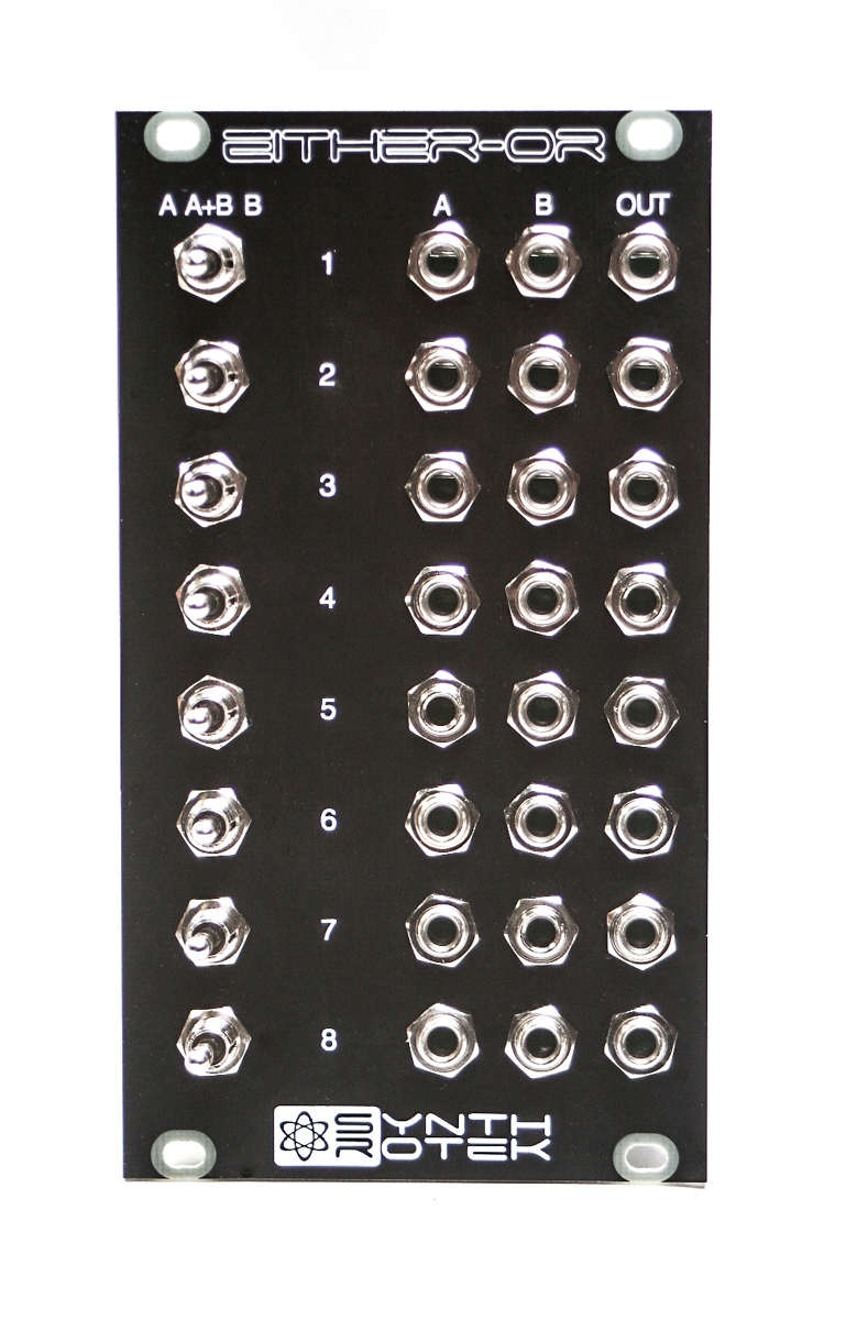
Either-OR Completed Unit
Testing Procedure
—TESTING OR LOGIC—
Make sure that all of the jumpers (shunts) are on all of the available headers on the back side of the modular. This will set up the A/B position of the switch to be a Combiner / OR Logic function.
TESTING WITH GATES / TRIGGERS:
Plug in a Gate or Trigger into Input A on Channel 1. Plug in another Gate or Trigger into Input B on Channel 1. Take the Output from Channel 1 and plug it into the input of a 1V/Oct Oscillator. Whichever Gate or Trigger is high will be passed through the Either-OR Output and will modulate the Oscillators frequency when the Channel’s switch is set to A/B (middle position).
Repeat the above steps for Channels 2 – 8.
TESTING WITH ENVELOPES / LFOS
Plug in a Envelope or LFO into Input A on Channel 1. Plug in another Envelope or LFO into Input B on Channel 1. Take the Output from Channel 1 and plug it into the input of a 1V/Oct Oscillator. Whichever Envelope or LFO is high will be passed through the Either-OR Output and will modulate the Oscillators frequency when the Channel’s switch is set to A/B (middle position).
—TESTING MUTE—
Pull all of the jumpers (shunts) off of the available headers on the back side of the modular. This will set up the A/B position of the switch to be a MUTE / OFF function. Follow the same steps above and confirm that when the Channel’s switch is set to A/B (middle position) that it does not pass any signal out of that Channel’s Output.
By now you should be able to confirm that your Either-OR module is working correctly. Thank you for choosing Synthrotek!