Important Links
Product Page
Store Page
Assembly Instructions
Bill of Materials
Quick Start Guide
Capacitor and Resistor Lookup Guide
Thank you for purchasing the Synthrotek RND kit! This is an easy to intermediate build. It is very important to get all the components properly soldered into the PCB in the correct placement. If you feel like you can handle it, please proceed! If not, get some help from a friend with experience or purchase a fully completed unit.
Please build according to the BOM, and not these instructions or the pictures alone. Some components may have changed since these were written, or we may not be able to get the exact looking components in the pictures.
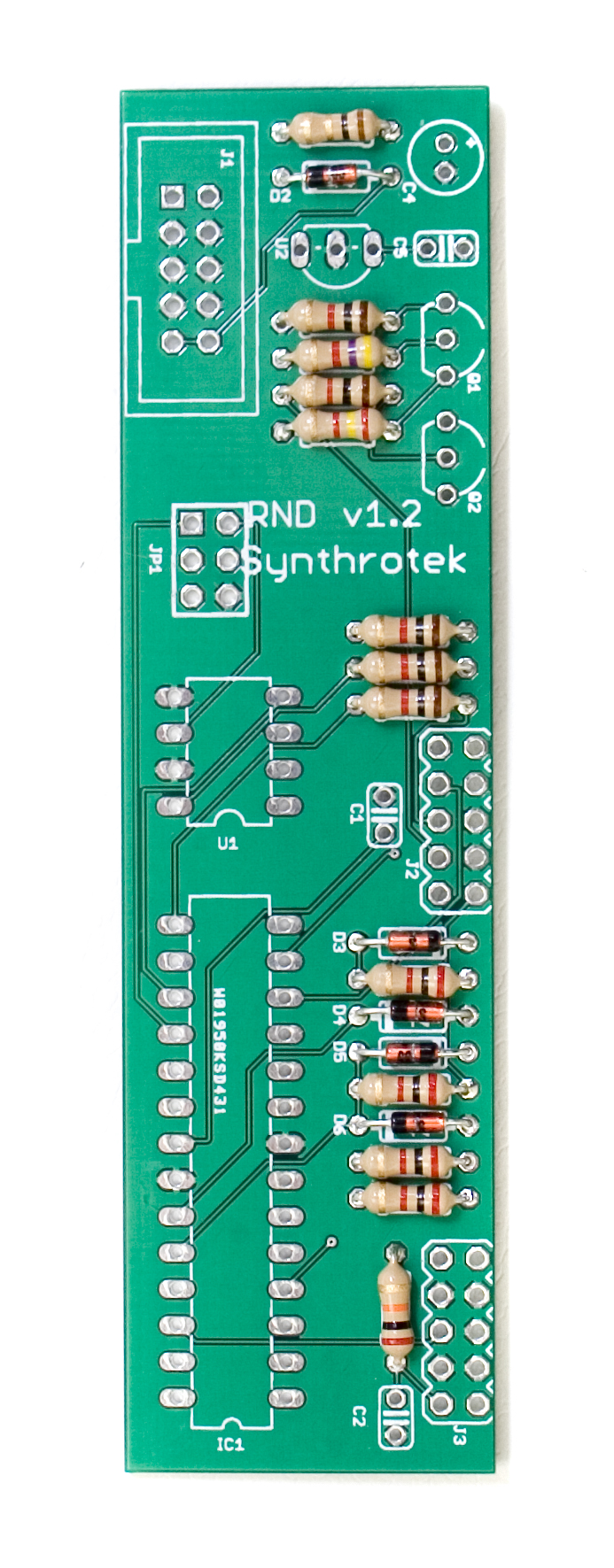
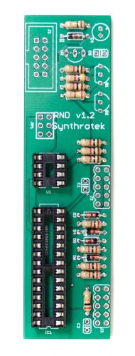
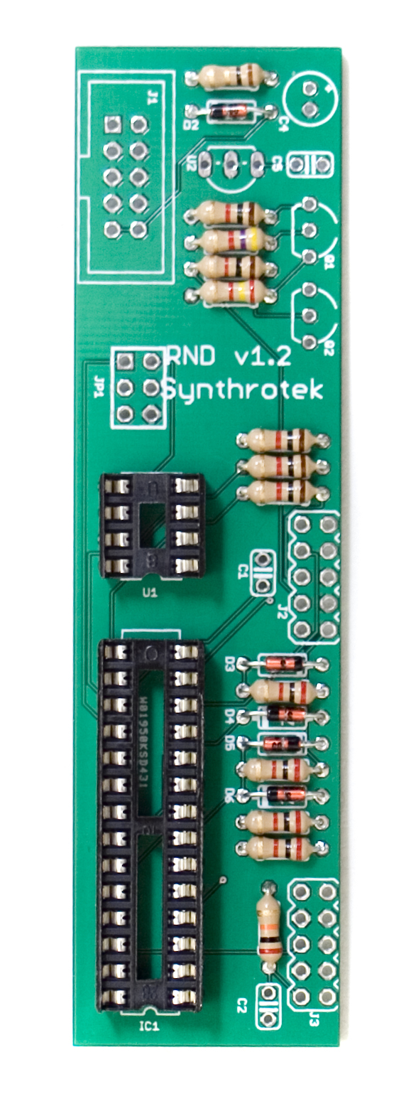
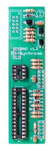
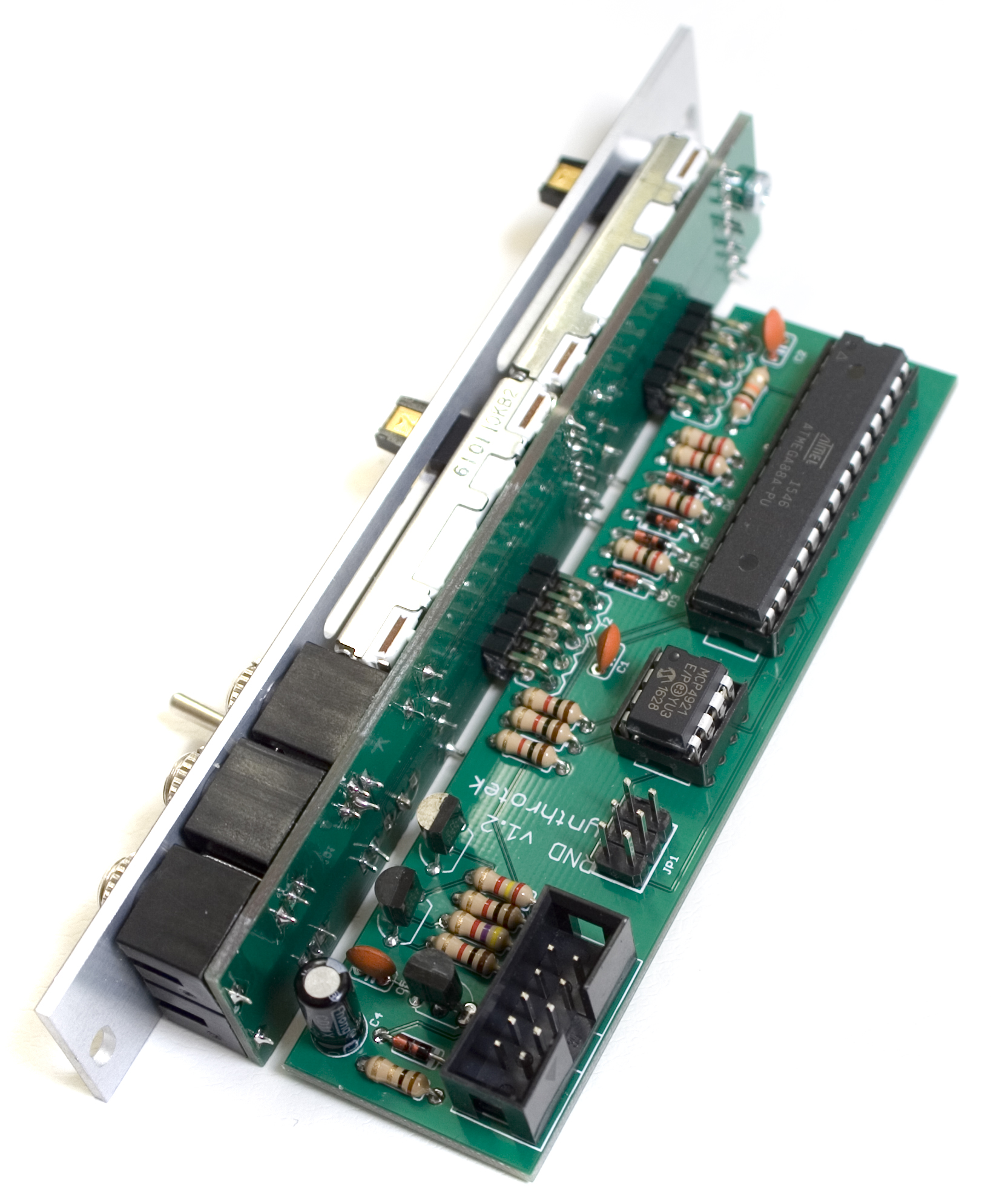
Logic Board Resistors & Diodes
Start by populating the resistors on the logic board. Resistors are non polarized, so it doesn’t matter which direction you put them on the PCB, but it will help with any troubleshooting that may arise if you line up all the tolerance bands (usually a gold stripe) on one side. This will make it easier to read the color codes on the resistors.
Next up are the diodes. These are polarized, so make sure to populate them with the cathode stripe in the same direction as indicated by the silkscreen.
Once everything is in place, carefully flip your project over, and solder the components in place. Clip any excess leads on the bottom of the board.
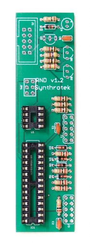
 IC Sockets
Next up are the IC sockets. Take care when populating these to not bend any of the legs, and to line up the notch in the end with the same notch that is displayed on the silkscreen. This notch indicates where pin 1 of the IC is. When you have them populated, carefully flip your project over and solder everything in place.
A trick to getting these nice and flat is to only solder one or two pins of each socket, and then reflow the solder joint while gently pushing on the top of the socket to seat it flat against the PCB. Then continue on and solder the rest of the pins, periodically checking for flatness.
 Ceramic Capacitors
Now we can populate the three ceramic capacitors. These are non polarized, and can be inserted either direction. Once they are in, carefully flip over your project and solder them in place, clipping the excess leads.
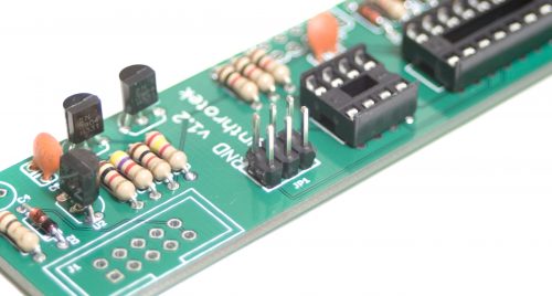
 Transistors and Voltage Regulator
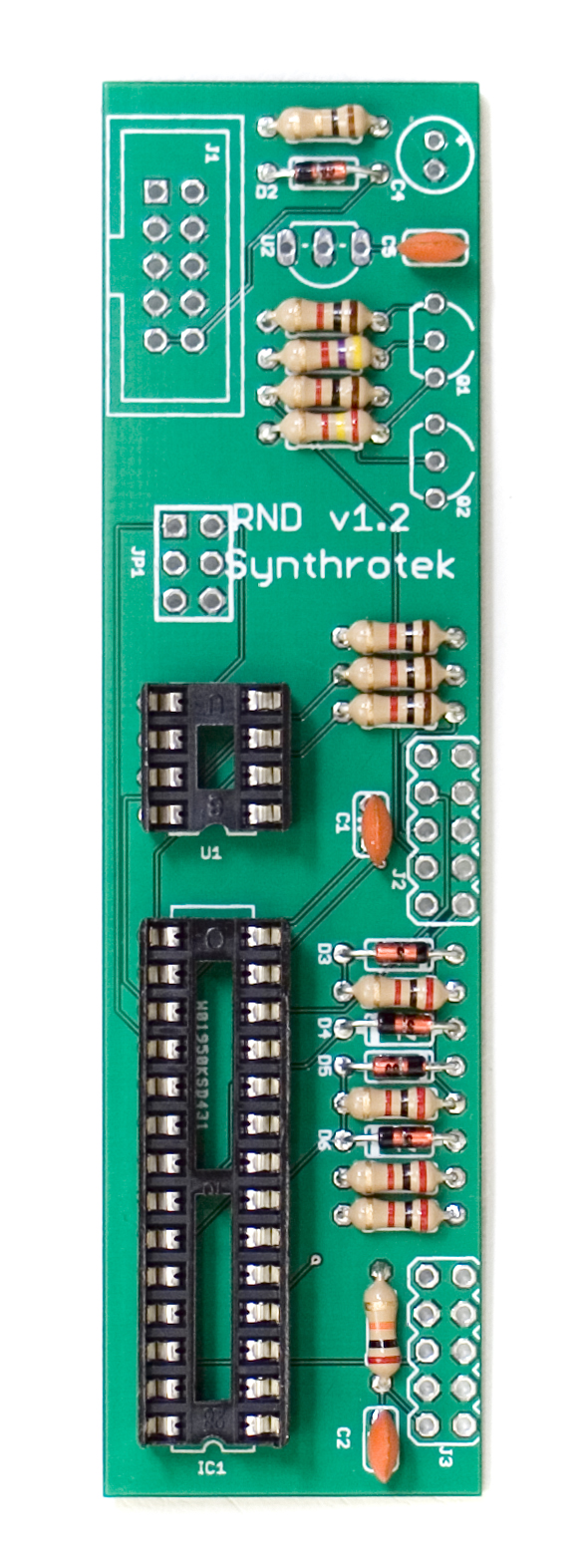
Next up are the two transistors, and the 5v regulator. These are all polarized, so make sure when populating them that you align the flat edge of the component with the corresponding flat line on the silkscreen. Also pay close attention to the number on the side of the component, as it is very easy to mix up the voltage regulator with the transistors, as they all look alike.
Once everything is in it’s proper place according to the BOM, carefully flip your project over and solder everything in place, clipping any excess leads on the bottom.
 ICSP Header (optional)
If you are going to re-program the RND at a later date, or sourced your own parts and need to program the module after building, you will need to populate this component and solder it in place. If you purchased a pre-made kit from Synthrotek or one of our distributors, you don’t need this header.
If you are populating it, just place it in the appropriate spot on the PCB, and then carefully flip the project over and solder in place. You can use the same trick that was used on the IC sockets to get this header to sit nice and flat as well.
 10 Pin Power Header

Next up is the shrouded power header. Make sure when populating this that the notch in the header is lined up with the notch designation in the silkscreen. (it’s on the side closest to the edge of the PCB).
When you’re sure that it is oriented correctly, carefully flip your project over and solder it in place.
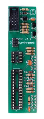 Electrolytic Capacitor

The electrolytic capacitor is the last component to be soldered onto the logic board for now. It is polarized, so take care when populating it. Ensure that the longer leg (the leg that is further from the stripe indicator on the body) goes through the solder pad with the little ‘+’ symbol next to it.
Once it is aligned properly, carefully flip your project over and solder it in place, clipping the excess leads on the bottom.
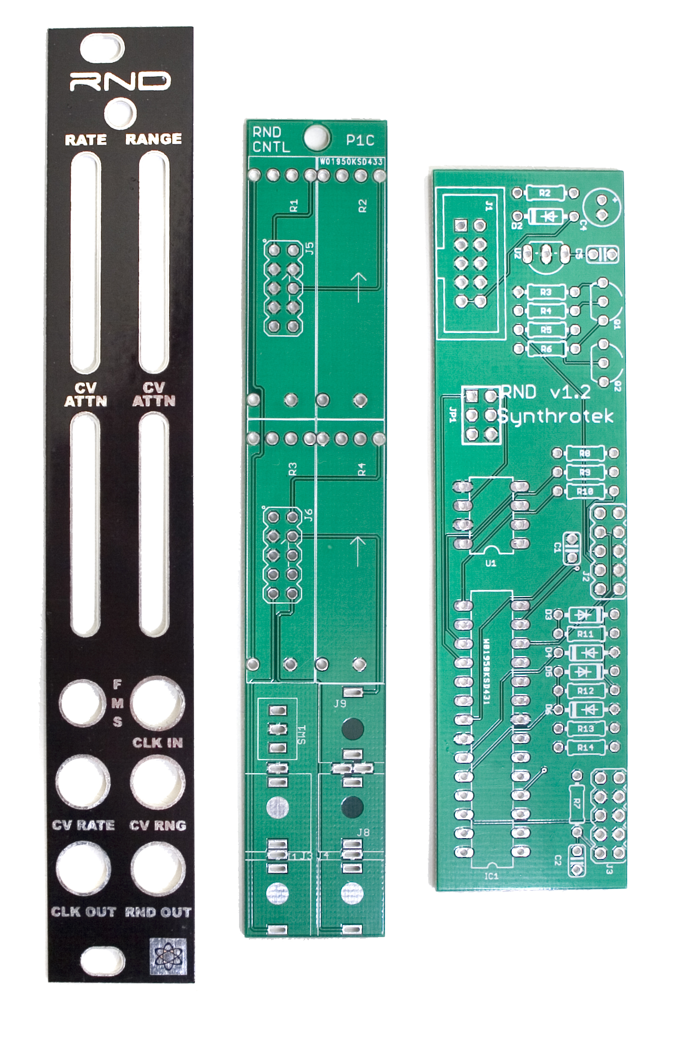
Control Board
Board to Board Headers
We are now going to start building the control board. We will start with the 5×2 right angle board to board headers. Make sure when you populate these that the side of the header without the bend in it goes through the control board. The black plastic stopper should be resting against the board.(see image below)
Make sure that you get these seated nice and flat against the board to ensure that everything will fit behind the front panel, and be at a nice 90 degree angle to the control board.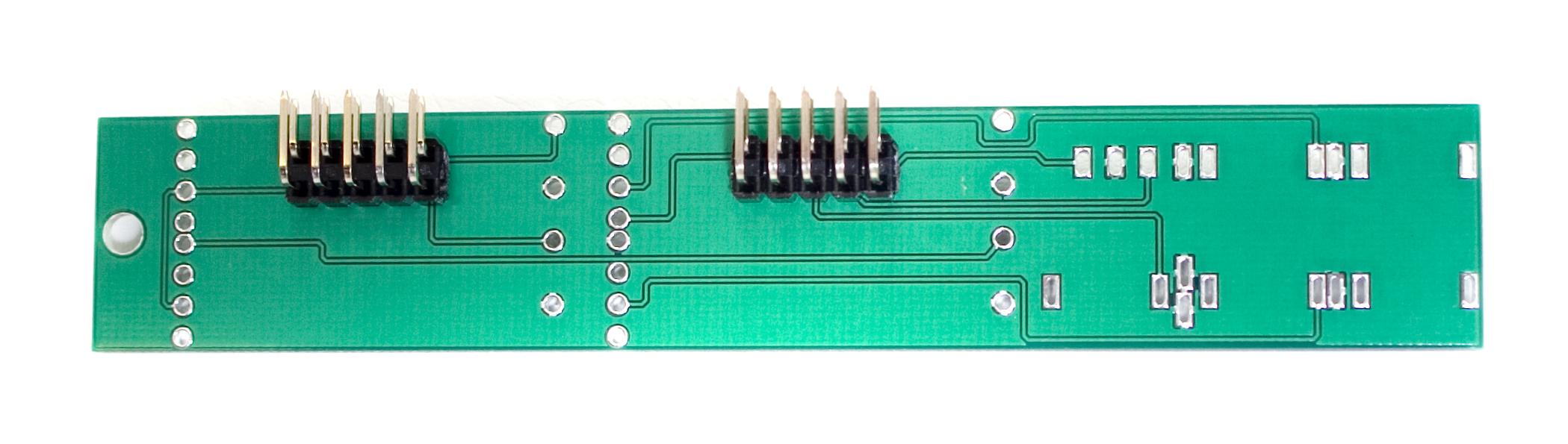 It is HIGHLY recommended to solder only one of the middle pins of these headers first, then re flow the solder and re-seat the header so it sits nice and flat. Take your time with these and make sure everything is straight and flat before soldering the rest of the pins in place.
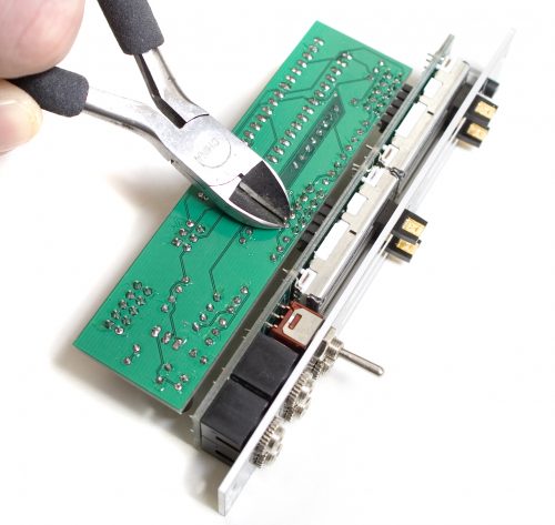
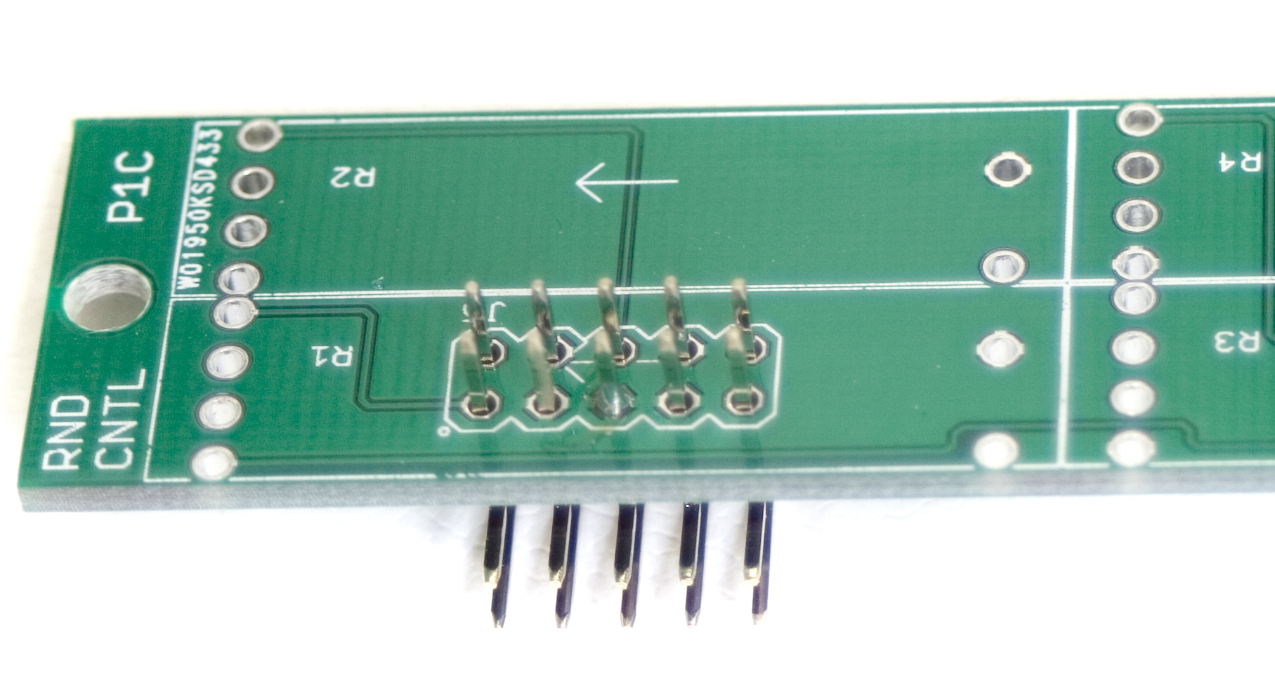 Once they are all soldered in place, we need to clip the pins that we just soldered down a little bit so that they don’t interfere with the slide potentiometers that need to go over them.
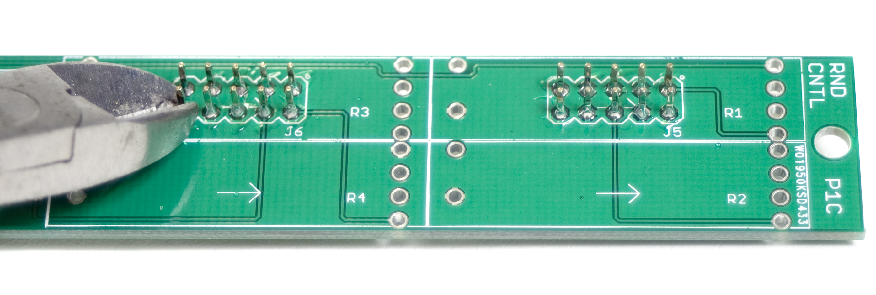 After clipping it is highly recommended to re flow all the solder joints on these guys, just to make sure that there aren’t any cold solder joints on these. They will be unaccessible after completing the build.
Slide Potentiometers
Next up are the slide potentiometers. These will only fit in the PCB one way, but the legs can get a little bent during shipping or general handling, so take your time and make sure they all get fitted properly into their respective solder pads.
Start by soldering just one leg on each side (top and bottom) of the slide potentiometer. Then, while gently applying pressure, re heat the solder joint to fully seat the potentiometer against the PCB. This will ensure they are all the same height after the front panel is assembled.
Once you are happy with how they are sitting, finish soldering the rest of the legs.
 Front Panel Components
DO NOT SOLDER ANYTHING ELSE UNTIL THE FRONT PANEL IS ON
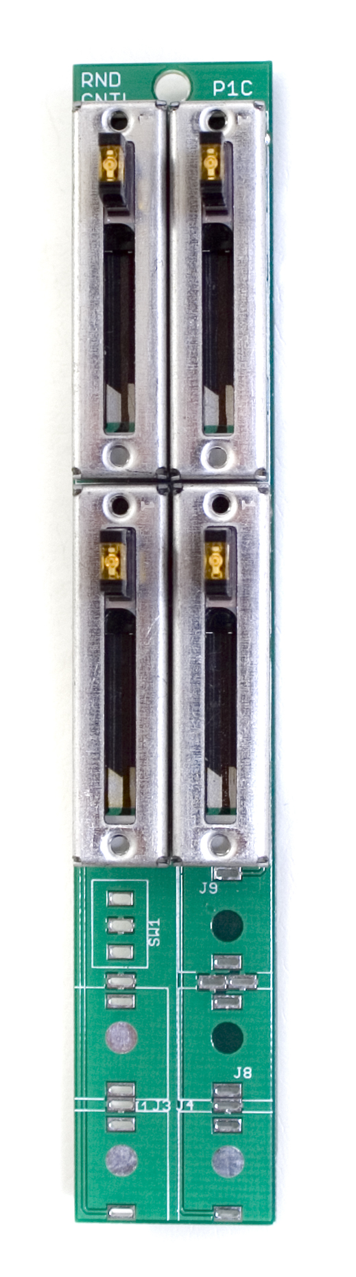
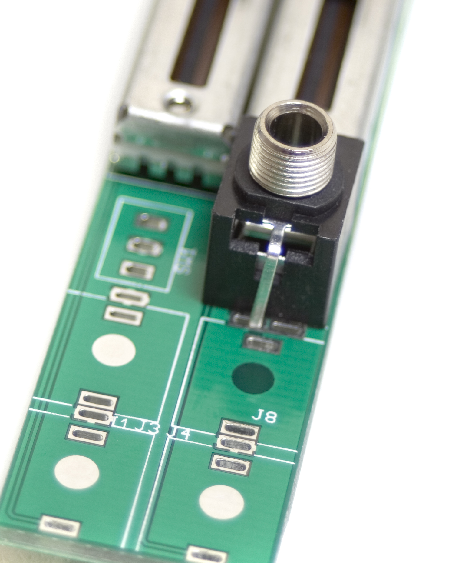
Now we are going to populate the remaining jacks and switch. For J8 and J9, we are going to have to bend the ground lead to the side just a little bit for them to fit properly.(see photo below) Don’t worry if they touch, as they are both ground signals, and it will not interfere with anything.
Next we are going to populate the aluminum hex standoff. You can do so by inserting a 2.5mm screw through the bottom of the board, and then spinning the hex standoff a little to get it started. Then use a phillips head screwdriver to tighten the assembly together.
Now populate the remaining three jacks and the switch. Once everything is in place (but not soldered!), carefully set the front panel down over everything.
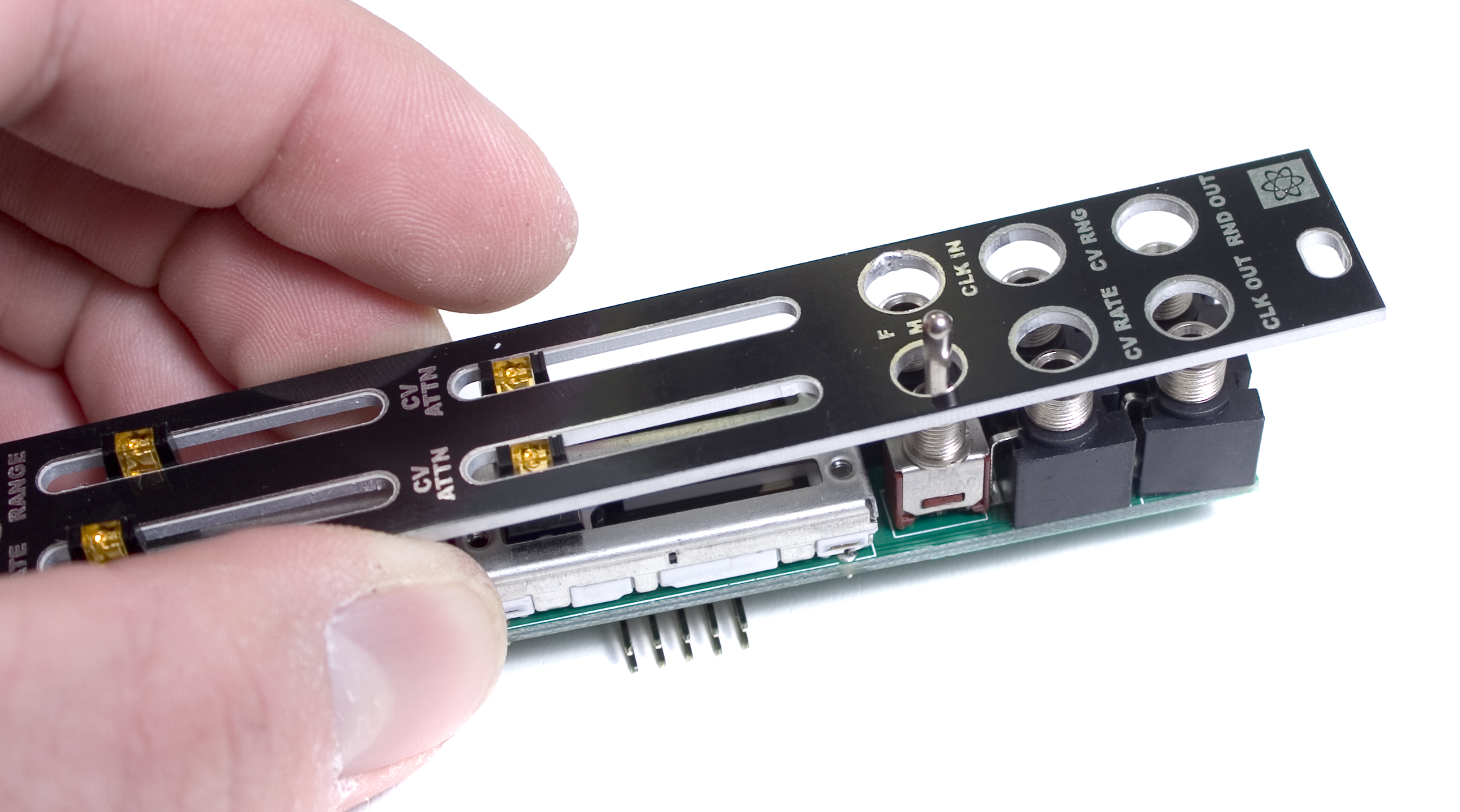 Next, grab your favorite tool (pliers not recommended!) and tighten down the nuts on everything.
 Then insert the black allen head screw through the front panel and tighten it down on the standoff.
\
Final Board Mating
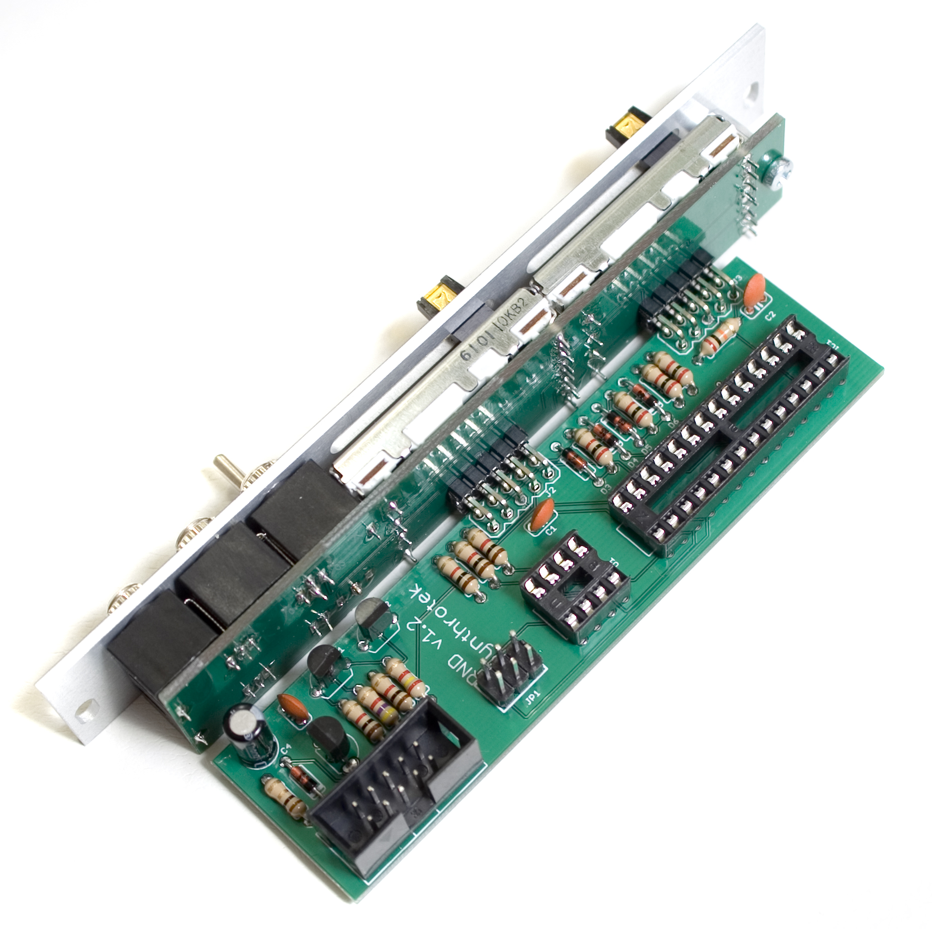
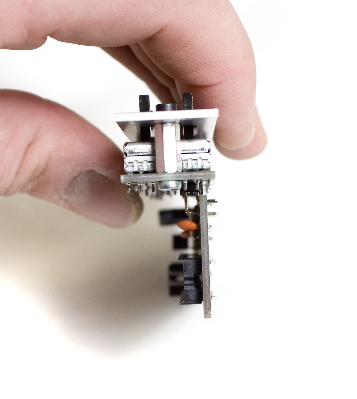
When mating the two boards, take care to make sure that everything lines up at a 90 degree angle. We can use the same trick as before with the headers on the control board to make sure that the logic board is sitting as flush to the bent part of the headers, and is coming straight off the control board. Solder just one pin of the header, and then re heat and straighten until you are satisfied with how it looks.
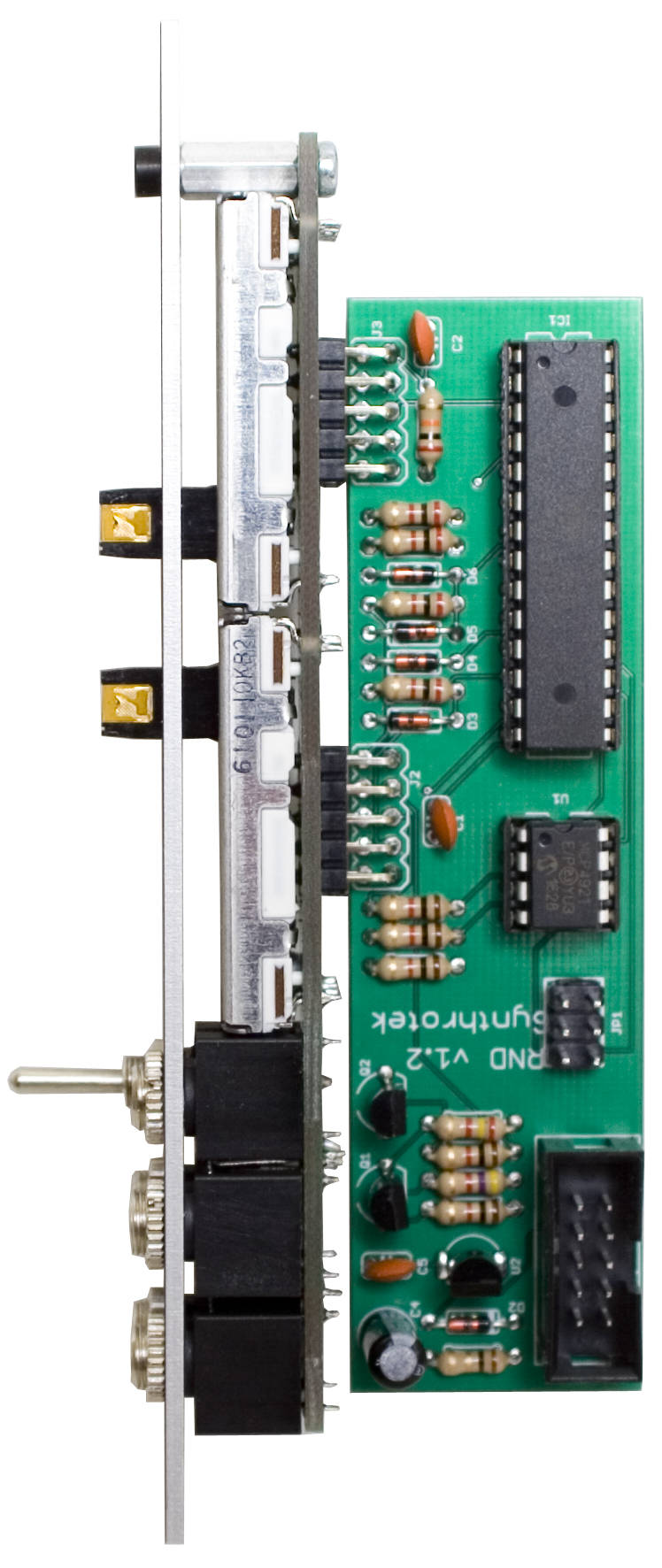
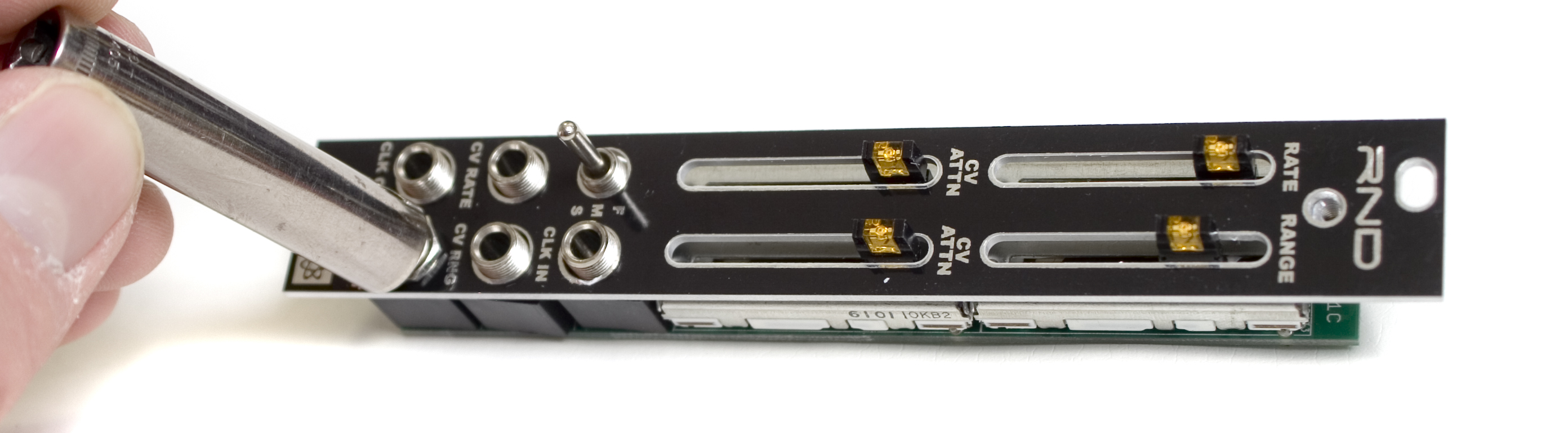
 Here is a side view that shows where your logic board should sit in relation to the control board.
 After you are happy with how it looks, solder the remaining pins, and then take your trusty clippers and clip the excess off the bottom of the pins, so they don’t bump into another module when installed in your system.
 ICs
ICs

The last, but quite crucial step is to insert the ICs into their sockets. Take care not to bend any legs of the ICs when doing this.
 Completed Unit
Congratulations on your completed RND module! If you sourced all your own parts, keep on reading for instructions on how to program your new module. If you purchased a kit, you’re done! Go make some music!