Important Links
Product Page
Store Page
Assembly Instructions
Bill of Materials
Quick Start Guide
Capacitor and Resistor Lookup Guide
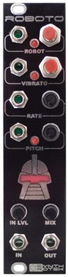
Thank you for purchasing the Synthrotek Roboto Kit! This is an intermediate build. It is very important to get all the components properly soldered into the PCB in the correct placement. If you feel like you can handle it, please proceed! If not, get some help from a friend with experience or purchase a fully completed unit.
Please build according to the BOM, and not these instructions or the pictures alone. Some components may have changed since these were written, or we may not be able to get the proper components in the pictures.
Lets Begin!
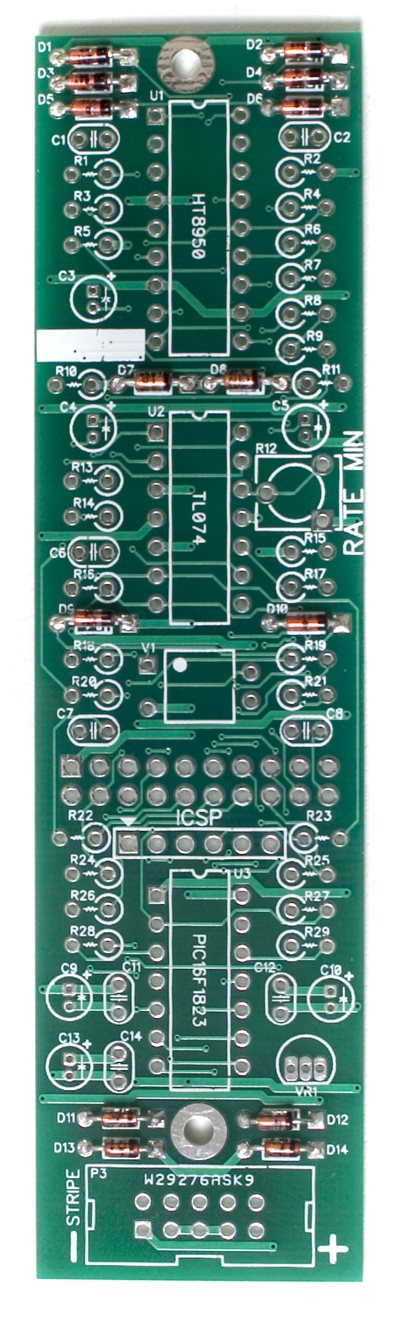
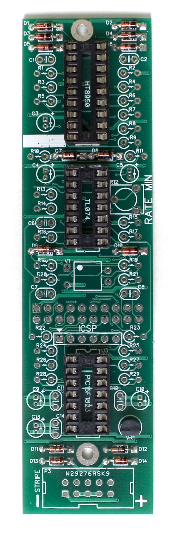
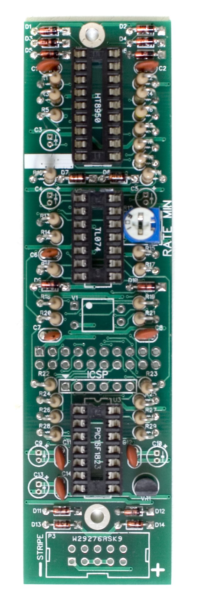
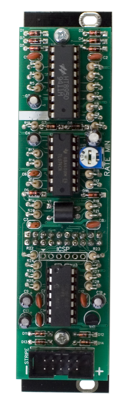
Diodes
We’re going to start with the diodes on the logic board. This project has three different kinds of diodes, so pay attention to the BOM and make sure they are in the correct spots. These are polarized, so make sure when you are populating them to get the cathode band (black stripe) aligned in the same orientation as indicated on the PCB by the stripe. Once they are populated, flip the project over, and solder them in place, clipping the excess leads.
 IC Sockets and Voltage Regulator
Next upare the IC sockets. Thesehave a semi-circular notch in one end that indicates pin1 on the IC, so it is important to make sure it is lined up properly. Put the side of the socket with this notch facing in the same direction as indicated on the PCB (towards the top of the PCB). Carefully flip your project over and solder it in place. In order to get it nice and flat, you can solder just one leg of the socket, then while applying gently pressure, reflow that solder joint so that it sits flat. Then go back and solder the remaining pins.
With the voltage regulator, match up the flat side on the regulator with the same flat spot that is indicated on the PCB. Be careful when soldering it in place that none of the legs create a solder bridge! One way to combat this is to solder one leg, then clip it, and then solder another and clip it, etc..
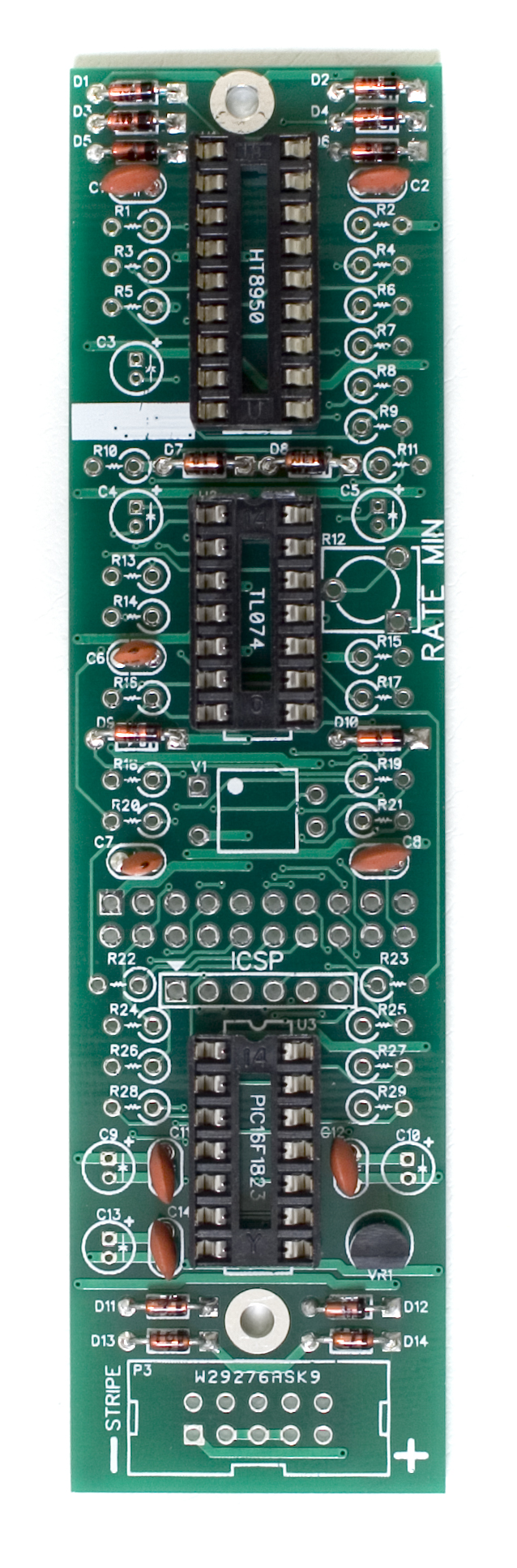
 Ceramic Capacitors
Now we can move on to the ceramic capacitors. These are non polarized, so it doesn’t matter which direction you populate them, but it will help with any troubleshooting that may arise if you populate them in a way that they can be easily read once the module is completed. When they are all populated, carefully flip your project over and solder them in place, clipping the excess leads.
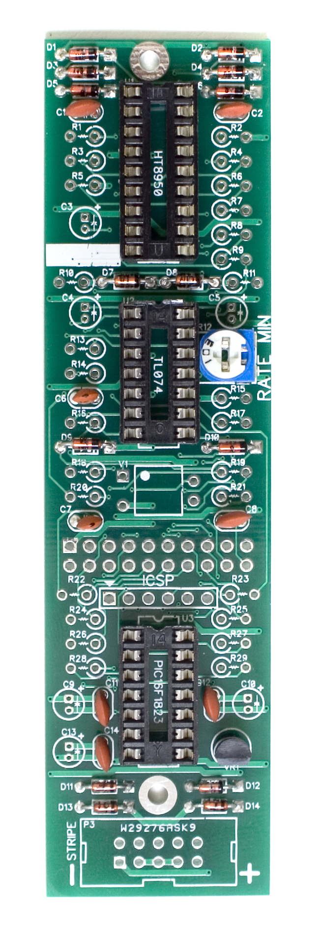
 Trimmer Potentiometer
Next up is the trimmer potentiometer. Populate the trimmer so that the flat side (the one with two legs on one side) is facing the edge of the board. When properly populated, carefully flip your project over and solder it in place.
 Resistors
The resistors on this project are ‘stand up’ resistors, which means they need to be bent so that both legs are facing the same direction. Below is an example of how they need to look. It is important not to make the bend right next to the body of the resistor, as when they are soldered in, this can cause undue stress on the body and may lead to failure.
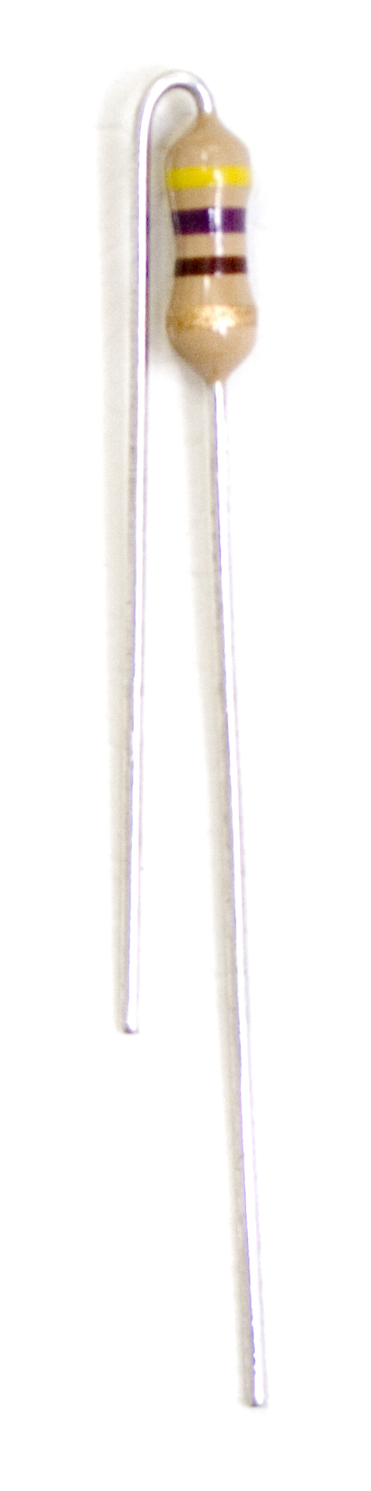 Resistors are non polar, but it can make troubleshooting easier if you populate them in such a way that all the tolerance bands (usually a gold stripe) are facing the same direction. This will make reading the color bands a lot easier. When you have them populated as per the BOM, carefully flip your project over and solder everything in place. Then clip the excess leads. A tip to get these guys sitting flat is to solder the longer leg of the two on all the resistors, and then go back and reflow each one while gently pushing on the top part of the resistor to sit it flat.
 Opto-Coupler (Vactrol)
Next up is the Vactrol. This component is polarized on one end, so it is VERY important to make sure you get the right alignment when populating it.
NSL-7053 Vactrol
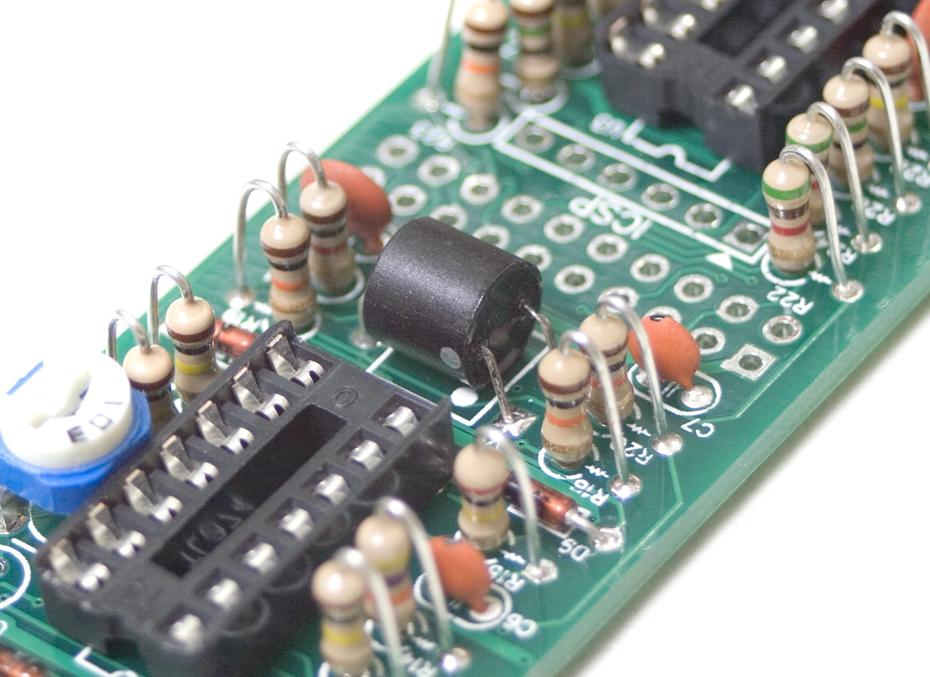
There is a small white dot on the side of the vactrol that needs to be lined up with the corresponding dot on the PCB. See the picture below for the proper alignment. You want to line it up so that the white dot is facing towards the IC socket that is directly above the vactrol, and so that the longer leads are facing towards the right side of the board.
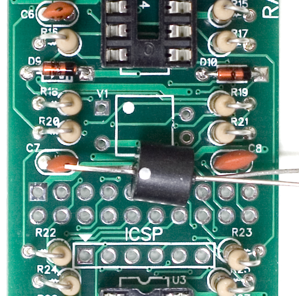
 Below is a close-up shot of the vactrol alignment.
VTL5C3 Vactrol
There is a small “+” sign on the side of the vactrol that needs to be oriented on the OPPOSITE side of the dot on the PCB. Look for the red + in the picture below for the proper alignment. You will need to bend the pins under the vactrol a little in order to get them to fit properly.
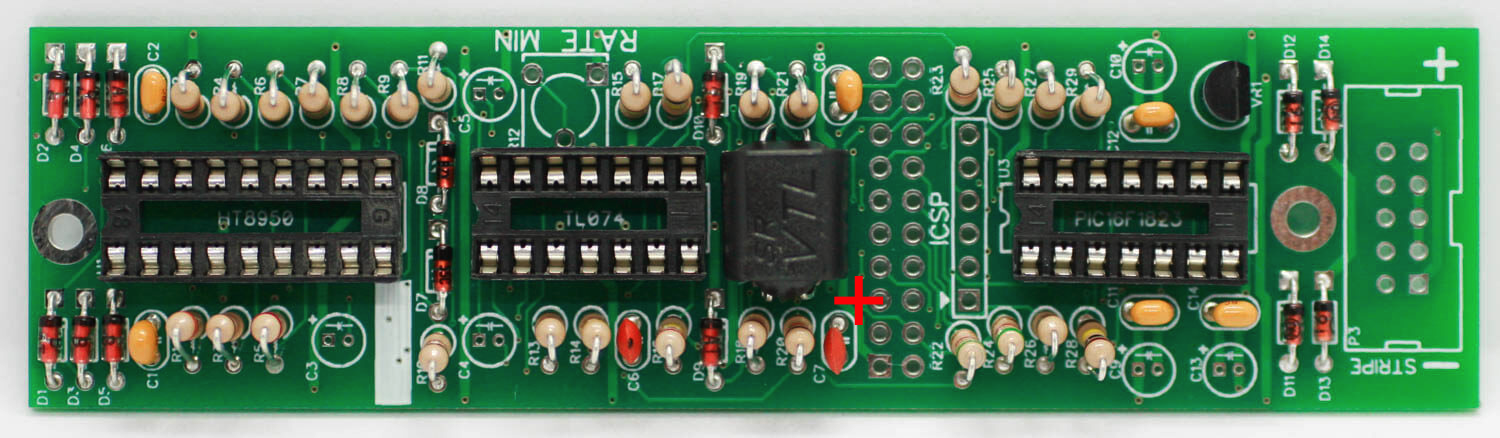
Align the + on the VTL5C3 with the red plus in the picture
10 Pin Shrouded Power Header
Now we can populate the keyed power header. When populating, it is VERY important to align the side of the header with the notch with the same indication on the PCB. If this gets soldered backwards, it will break your module. When soldering this in place, you can use the same trick as on the IC socket, with only soldering one pin, then coming back and making sure its flat and then soldering the rest of the pins.
Electrolytic Capacitors
Next up are the electrolytic capacitors. These guys are polarized, so take care when populating them. There is a small ‘+’ on the PCB that indicates where the longer of the two leads needs to go. When populated, the stripe on the capacitor should be facing away from the ‘+’ symbol. When you are happy with their placement, carefully flip your project over and solder everything in place, clipping the excess leads.

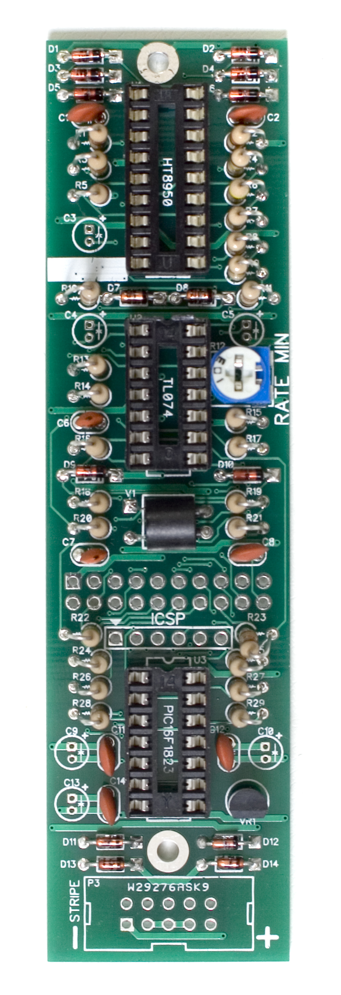
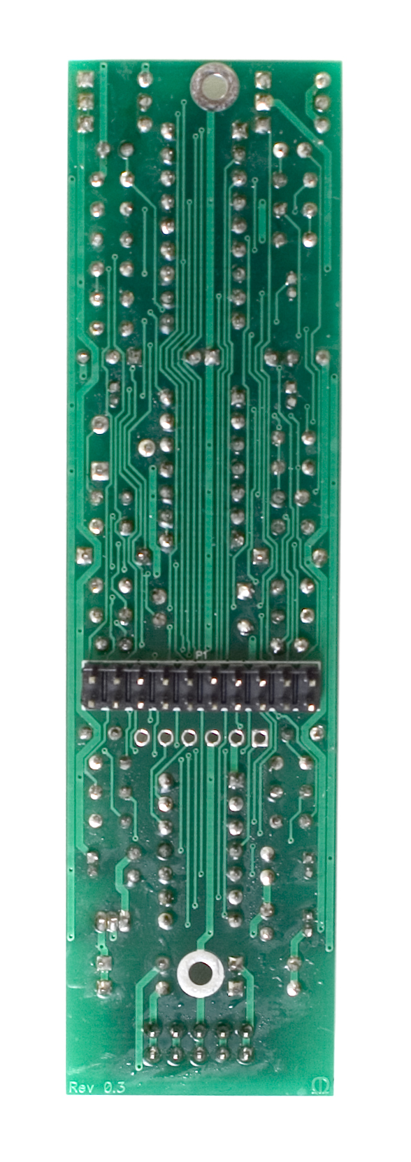
20 Pin Board to Board Header
The last component on the logic board is the 20 pin header that will connect the two PCBs together. Flip your project over and populate the header. Then carefully flip the project back over and solder the header into place. You can use the same trick that we used earlier with the IC sockets to get the header nice and flat to the PCB. It is imperative that the header is nice and straight, otherwise the boards won’t mate properly later!
Control Board Resistor and 5mm LED
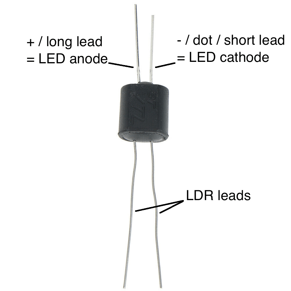
Next up is the single resistor and the 5mm LED on the control board. Populate the resistor as we did above with the logic board. The LED is a polarized component, so when populating it, make sure that you align the flat side of the LED with the flat side that is indicated on the PCB. The shorter leg of the LED should be going through the solder pad closer to the left side of the PCB, as shown below.
When soldering these components into place, make sure that the LED is nice and flat and sitting straight. This is the LED that will be lighting up the robot’s visor on the front panel. After you are satisfied with the placement, solder everything in place and clip any excess leads.
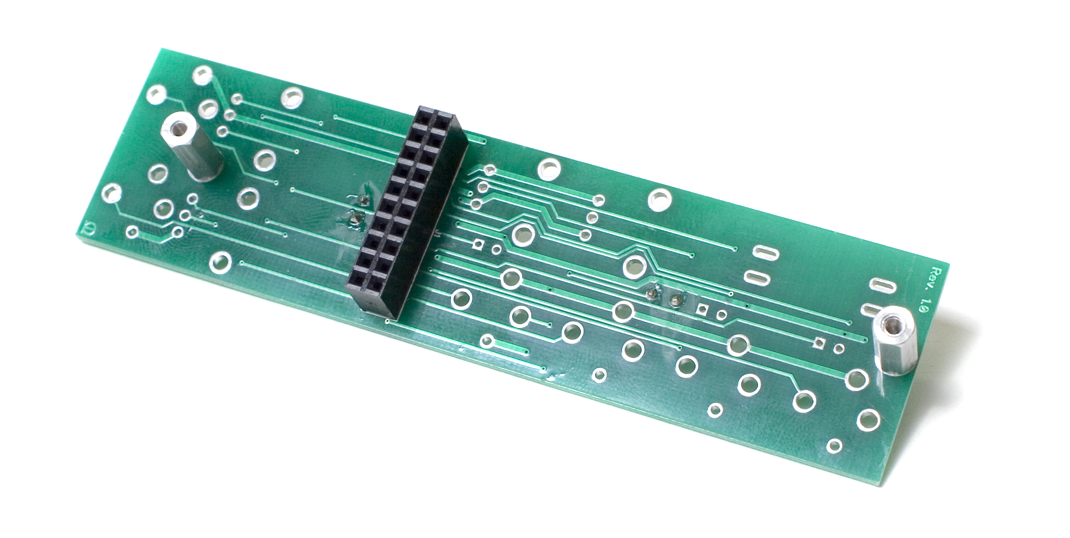
Control Board 20 Pin Socket and Hex Standoffs
Now we are going to populate the 20 pin socket that is the mate to the header on the logic board. Using the same methods as above, solder the socket onto the back side of the control board.
After you are satisfied with the socket’s placement, install the hex standoffs onto the control board. An easy way to do this is to insert a 2.5mm screw through the hole on the control board, and then screw the standoff onto the screw. Once it is finger tight, you can use a phillips head screwdriver to give it an extra little turn.
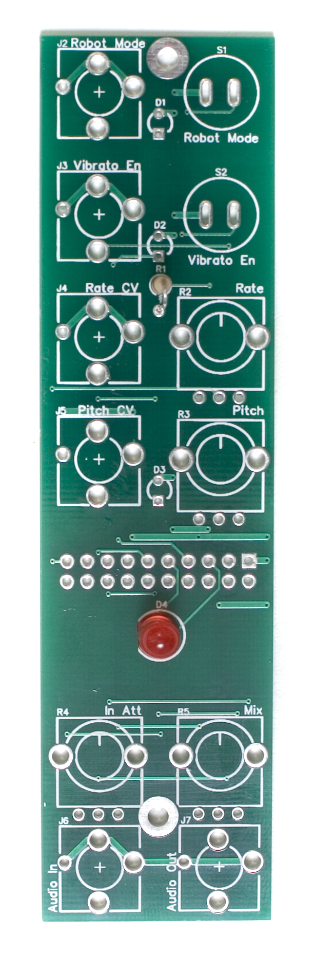
Component Placement
Next up are all the front panel components: pots, switches, jacks and LEDs. Note that these LEDs are also polarized, so make sure that the shorter leg of the LED goes through the solder pad that is square shaped.
DO NOT SOLDER ANYTHING YET!
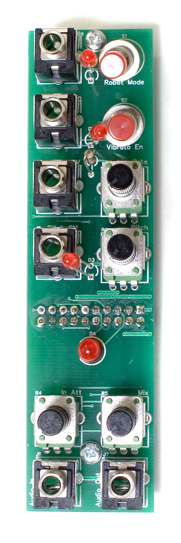
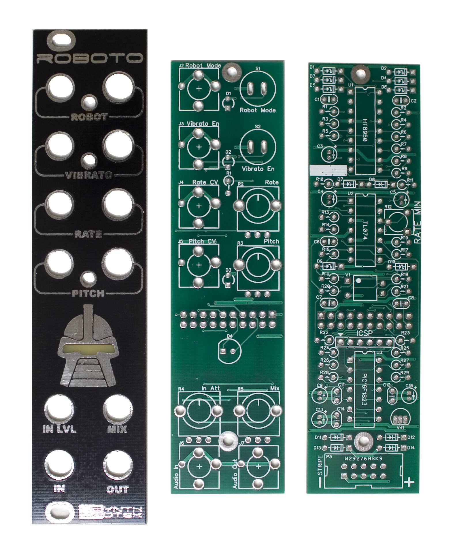
Front Panel Placement
Next we will place the front panel over all of the components we just populated.
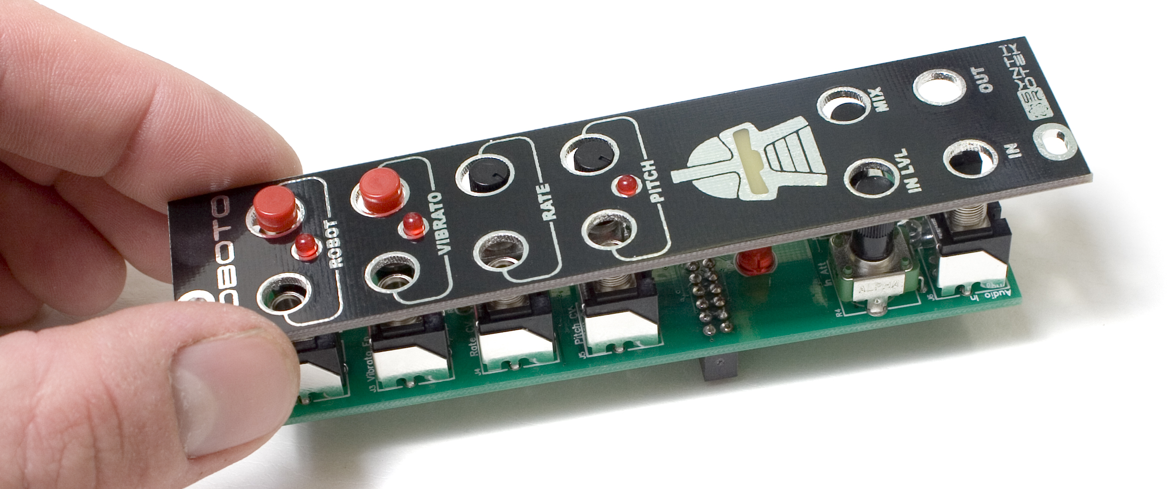
Then carefully thread the nuts onto the components by hand, and come back with a tool to tighten them. Be careful not to over tighten!
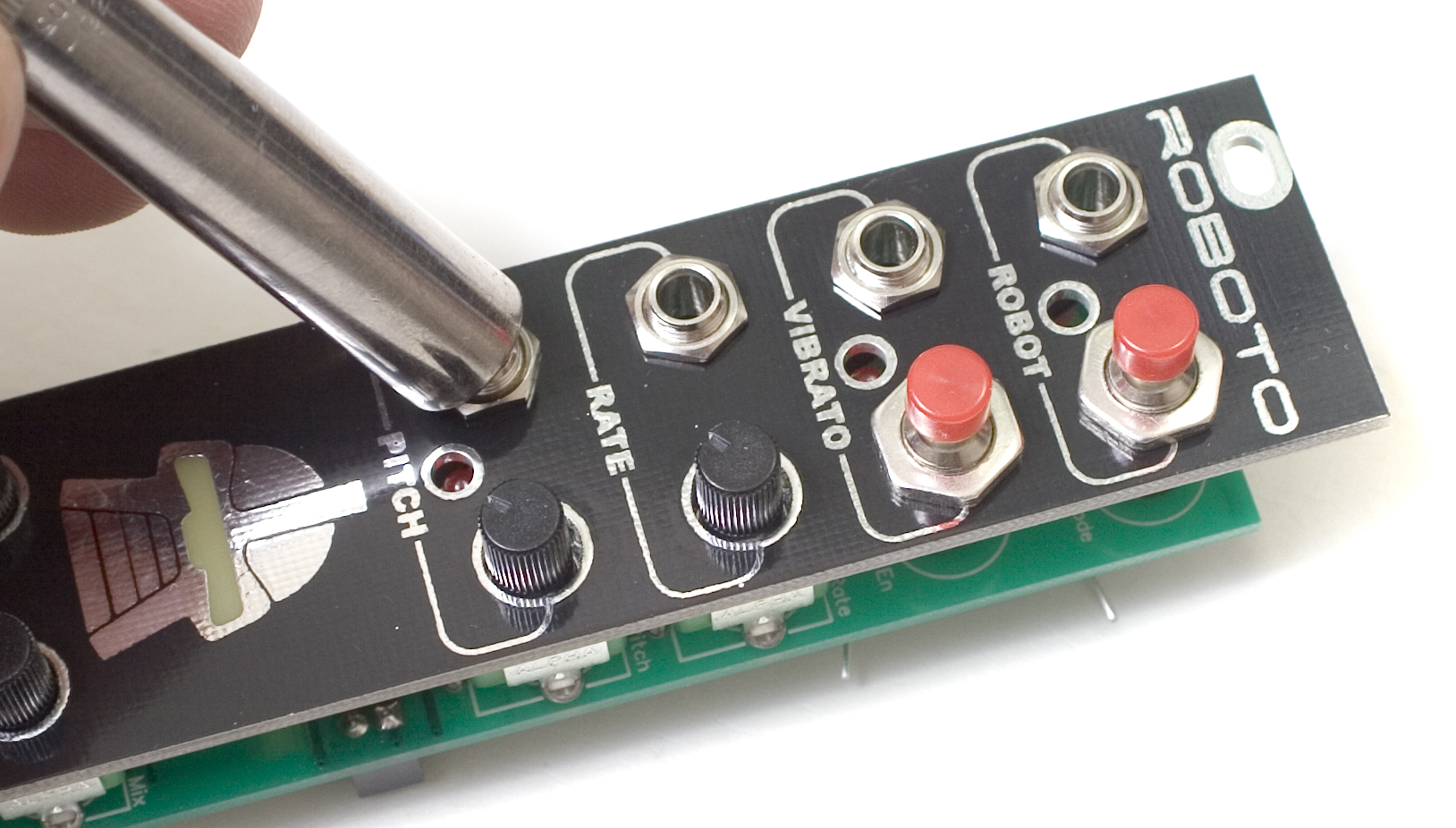
Next, take a close look at all of the components, and make sure they are sitting flush with the PCB and that they are straight. Once you are happy with the placement, carefully flip your project over and solder everything into place.
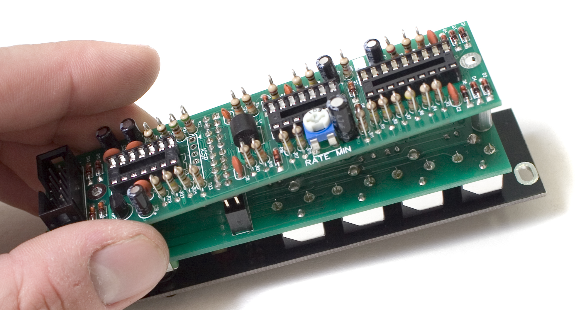
Final Assembly
Now we are ready to finish the assembly of the project. Carefully take the logic board in one hand and the control board / Front panel assembly in the other, and insert the header from the logic board into the socket of the control board. Make sure that you have the orientation right! The power header should be on the bottom of the project, as shown below. It’ll be easy to tell if the boards are backwards, because the logic board won’t line up with the control board.
Now would be a good time to go ahead and insert all the ICs. Just like the sockets, make sure that when you are populating the ICs that you align the semi-circular notch in the IC with the same notch in both the socket and the PCB.
Finally, grab two more 2.5mm screws, and insert them through the logic board and into the hex standoffs. Use your phillips head screwdriver to tighten them down, holding the two boards together.
Completed Unit
Congratulations!! You’ve just completed building the Synthrotek Roboto DIY Kit!