


Important Links
Product Page
Store Page
Assembly Instructions
Bill of Materials
Quick Start Guide
Capacitor and Resistor Lookup Guide
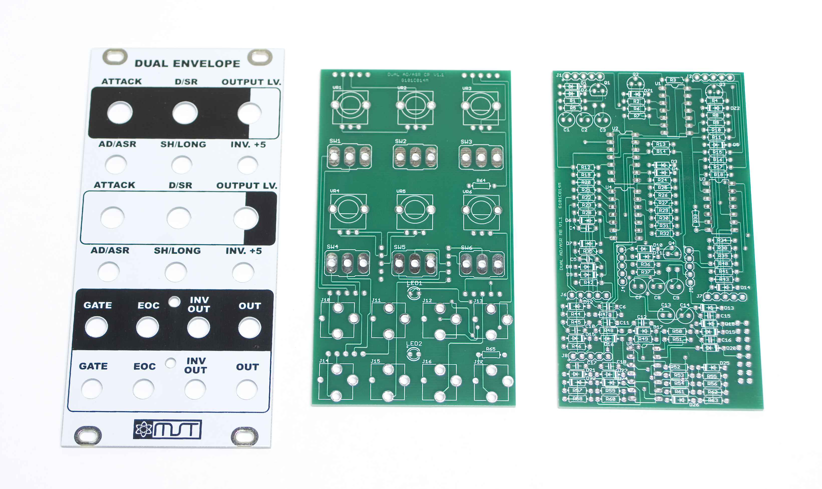
MST AD/ASR Dual Envelope PCB and Panel Set
Thank you for purchasing the MST AD/ASR Dual Envelope Eurorack module kit! This is an intermediate build. If you feel like you can handle it, please proceed! If not, get some help from a friend with experience or purchase a fully completed unit.
ATTN: Please follow the BOM and these instructions and don’t populate from the PCB or these instruction pictures alone. Also sometimes we cannot get the exact pictured components, so please look over your parts and check the codes first.
Lets begin!
DIODES
Start with the diodes as shown below, then turn over on a firm surface to solder, then clip your leads. Diodes are polarized components so you must match the black stripe on your diodes with the white stripe on the PCB silkscreen. This build has two zener diodes in it, DZ1 and DZ2, identify and place these first so as to avoid putting them in the wrong spot.
MST Dual Envelope Diodes
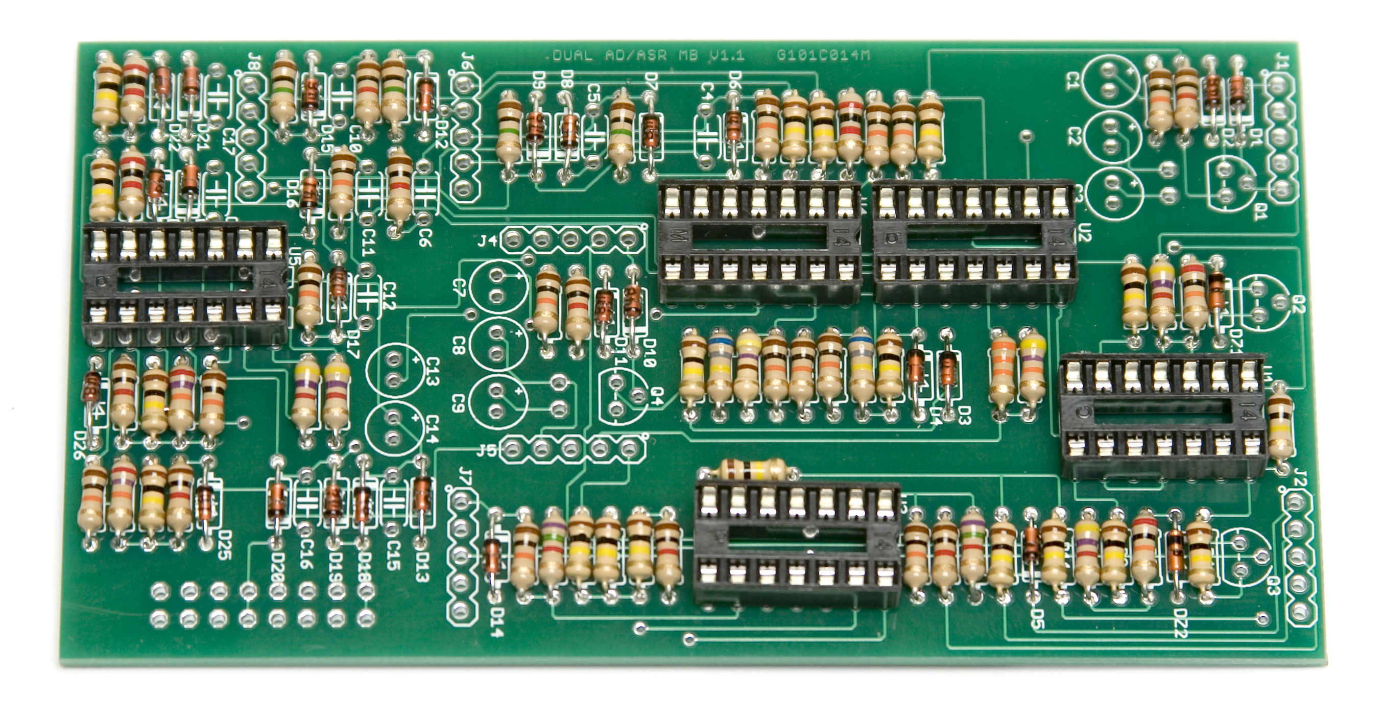
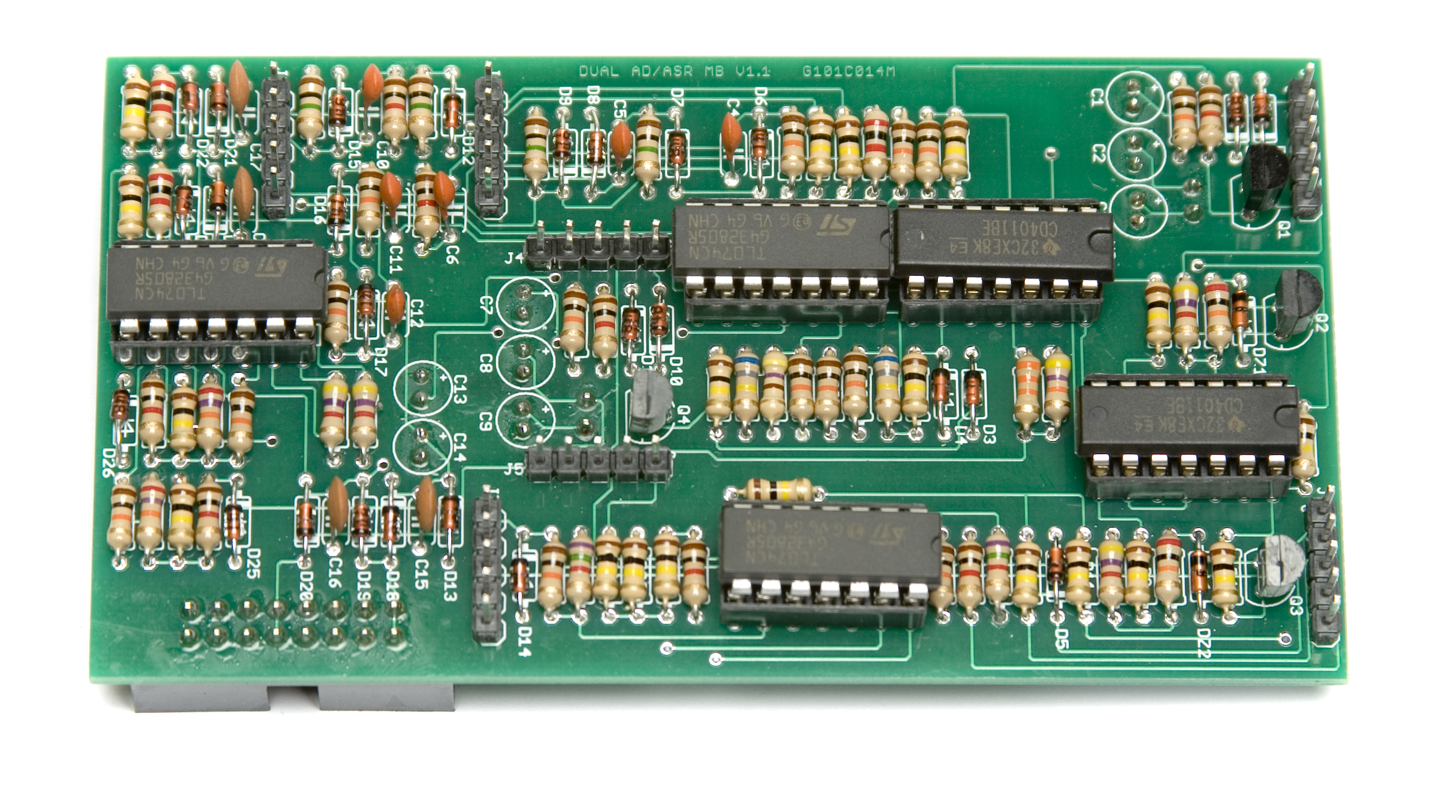
RESISTORS
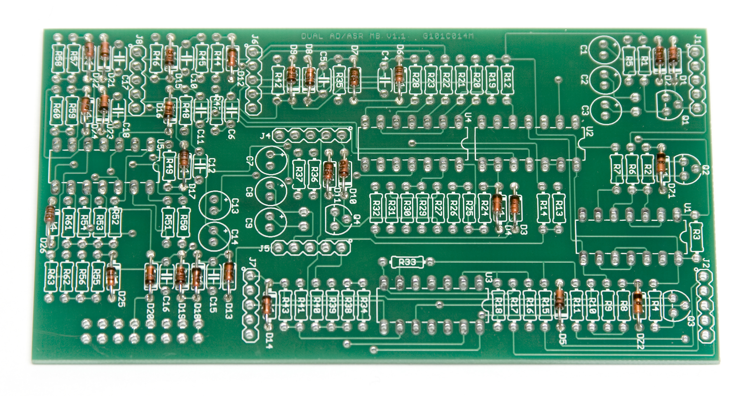
Populate first, then turn over on a firm surface to solder and clip leads. Using a flat rigid card or another PCB can help hold the resistors in place as you turn the board over. With the density of resistors in this build, it is recommended to only solder the leads you can comfortably get to, with at least getting one leg of every resistor, then clip the ones you’ve soldered and then continue soldering. OR you can populate roughly half, flip and solder, then do the other half.
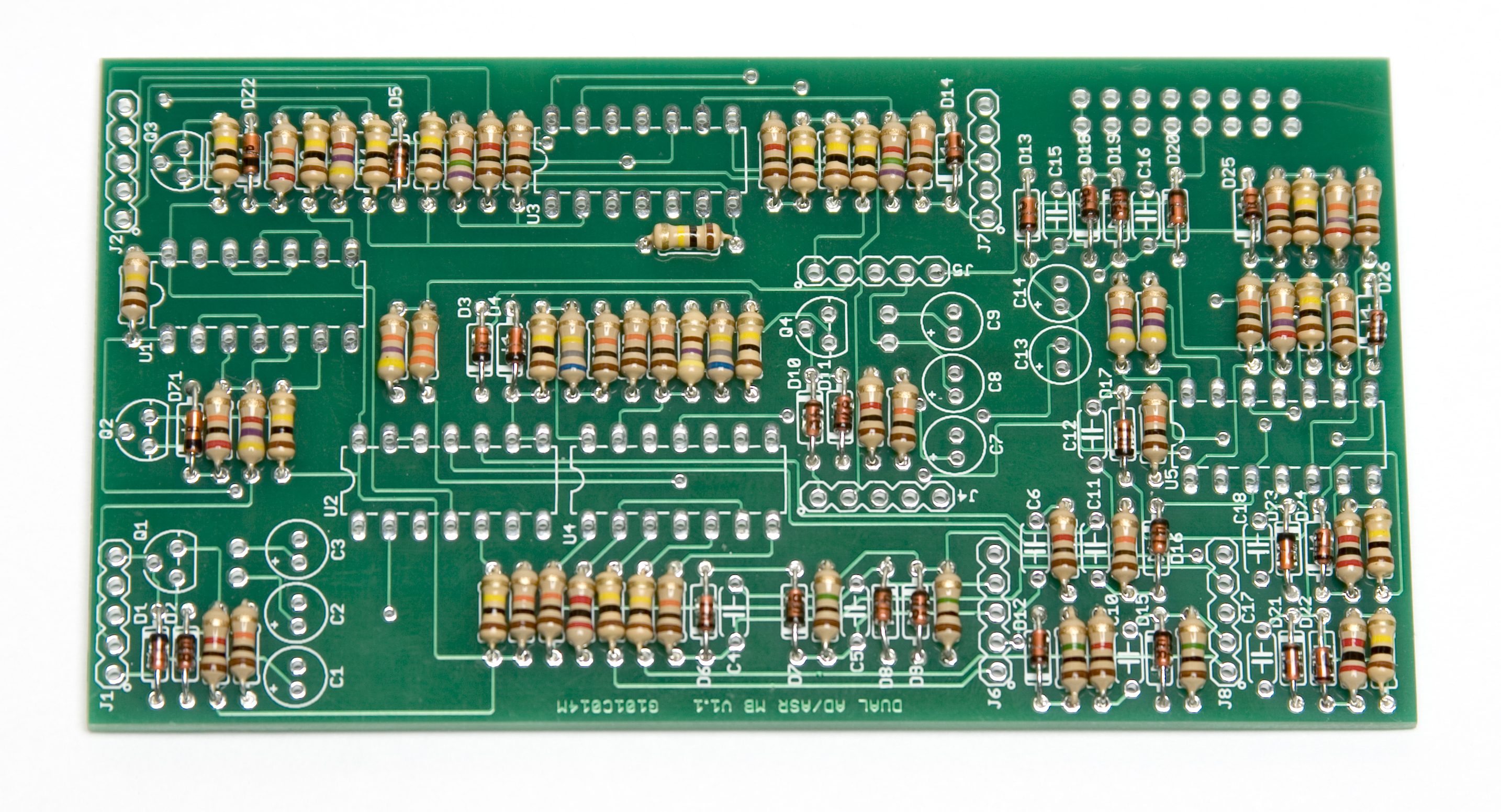
MST Dual Envelope Resistors
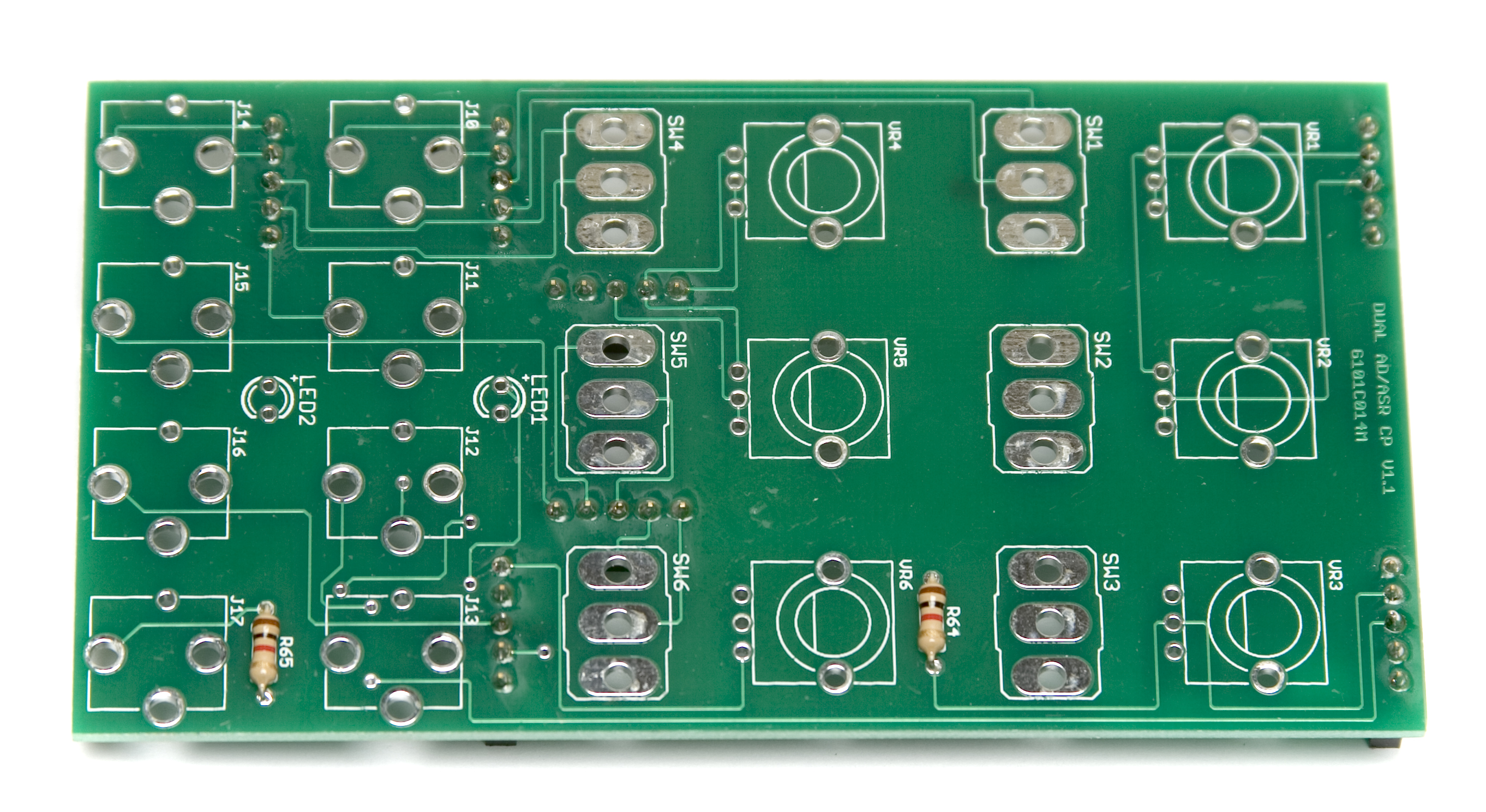
Now would be a good time to also populate the resistors on the control panel. Like the logic board, populate and then flip over and solder.
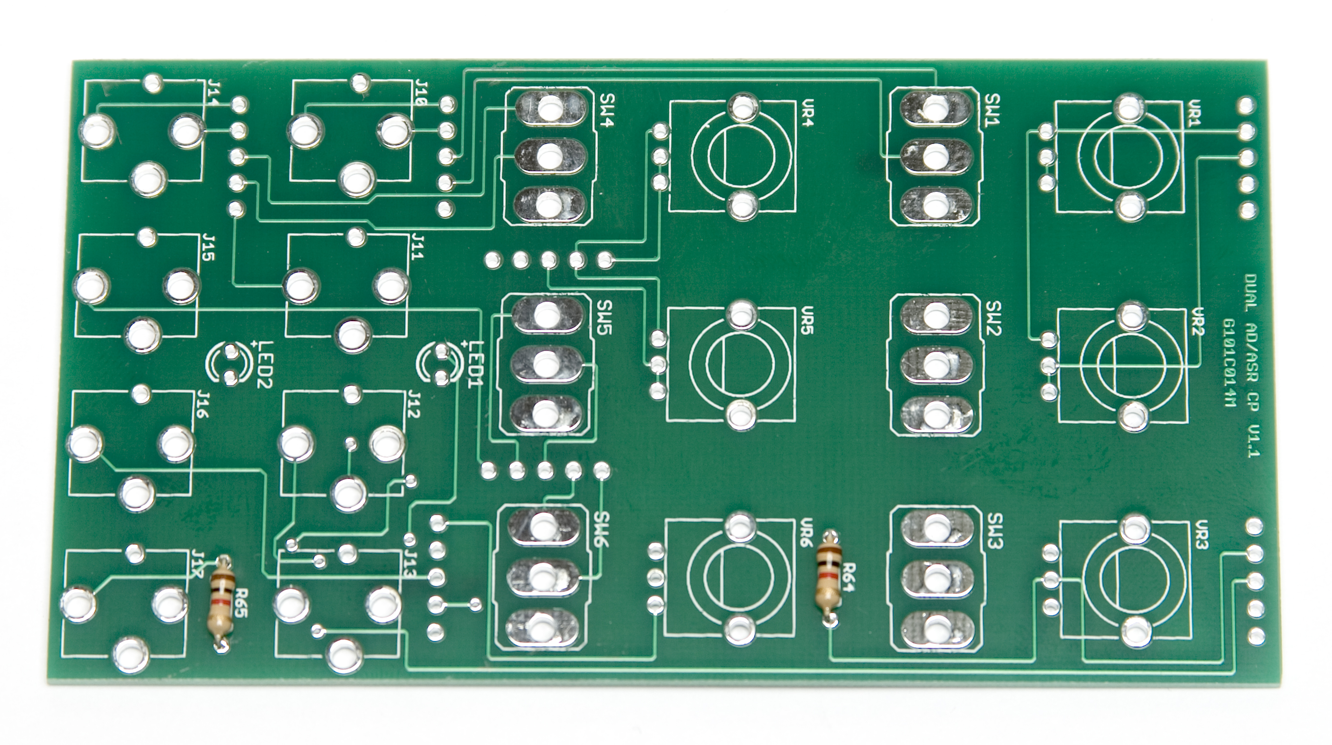
Dual Envelope Control Board Resistors
IC SOCKETS
Place the IC Sockets by aligning the notch with the notch graphic on the PCB Silk Screen. Turn over on a flat surface and solder into place.
Dual Envelope IC Sockets
CERAMIC CAPACITORS
Add the ceramic capacitors as shown below. Turn over to solder and clip leads. If you have trouble with getting your ceramic caps to sit straight, you can solder one leg of them, then while heating them with your iron, re-adjust them so they are centered. BE CAREFUL not to burn the solder pad or PCB while doing this.
DO NOT SOLDER THE ELECTROLYTIC CAPACITORS YET. (see below)
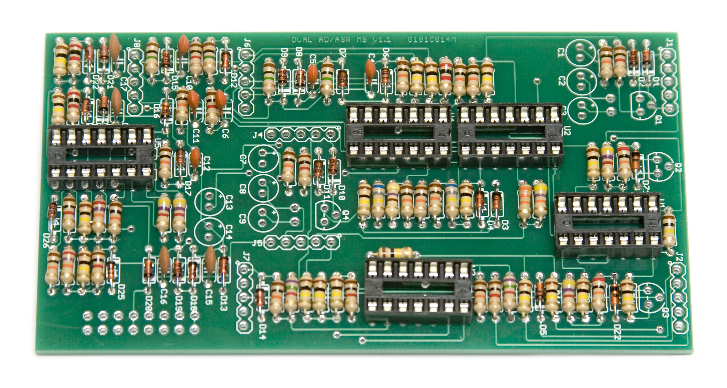
Dual Envelope Ceramic Caps
TRANSISTORS
Next, insert the transistors into their correct positions as per the BOM, then turn over and solder, then clip the leads. If having trouble getting them straight, you can use same trick as with the ceramic caps. (this trick can be used on virtually any component)
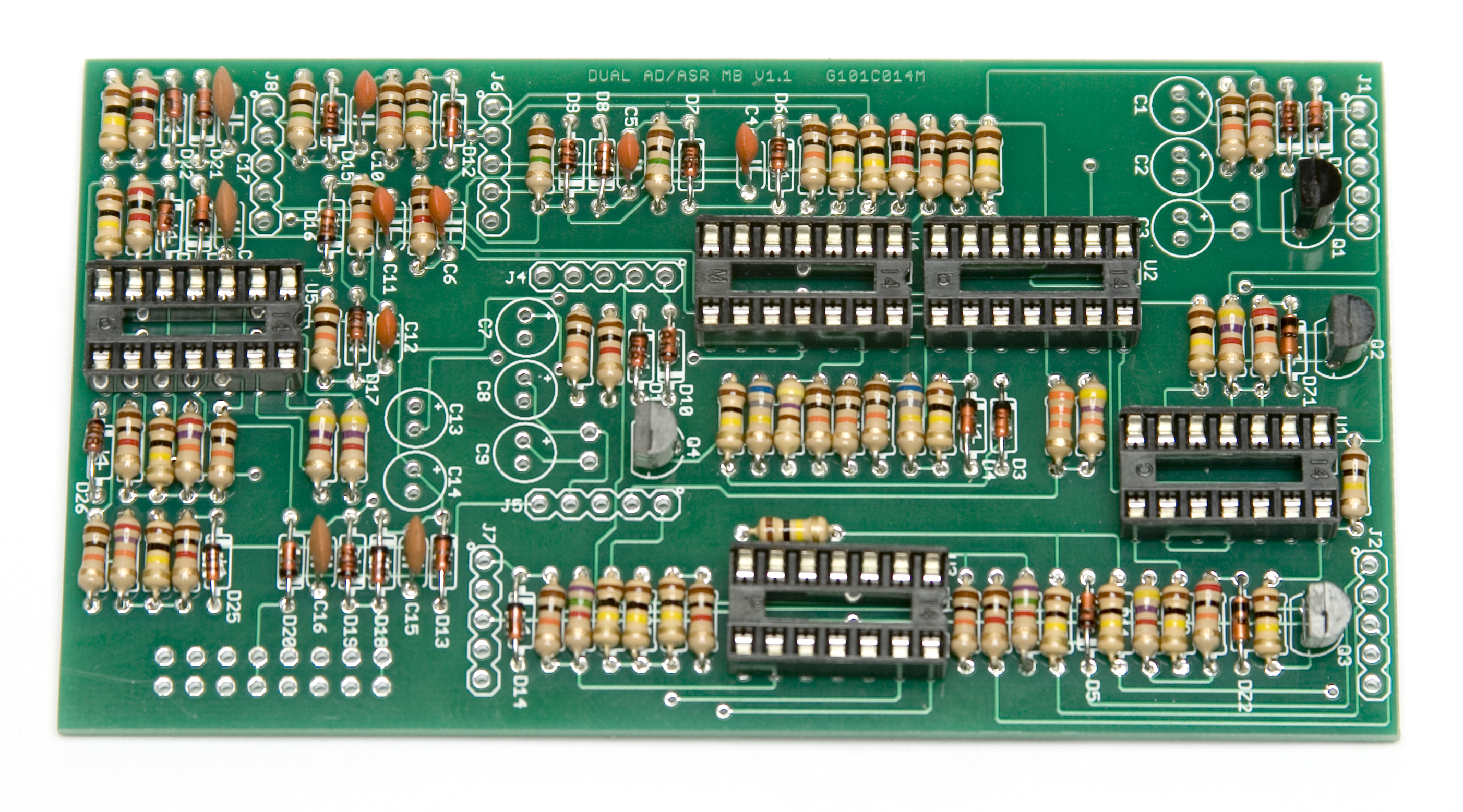
MST Dual Envelope Transistors
5 PIN MALE HEADERS
Now place the 5 pin male headers into their proper spots on the board. Then turn over to solder. There really isn’t an ‘easy’ way to do this, but some luck has been had by first SLIGHTLY filling the middle hole for the header. While holding the header to the board, apply LIGHT pressure and re-heat the solder. The header should slide down into place.
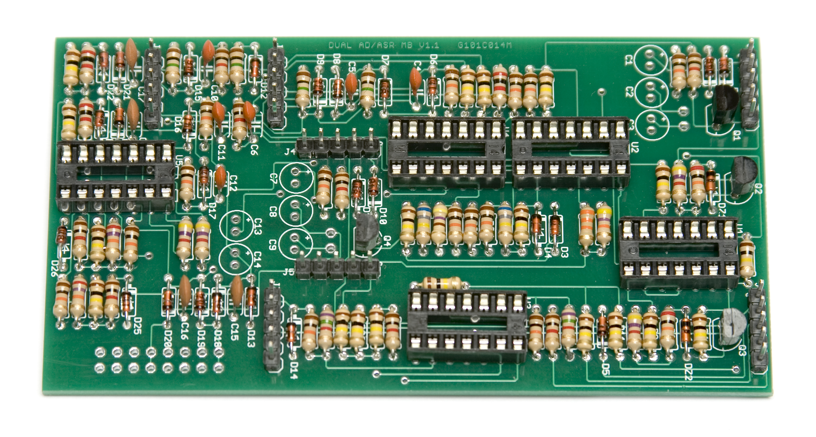
Dual Envelope 5 Pin Male Headers
2 PIN MALE HEADERS
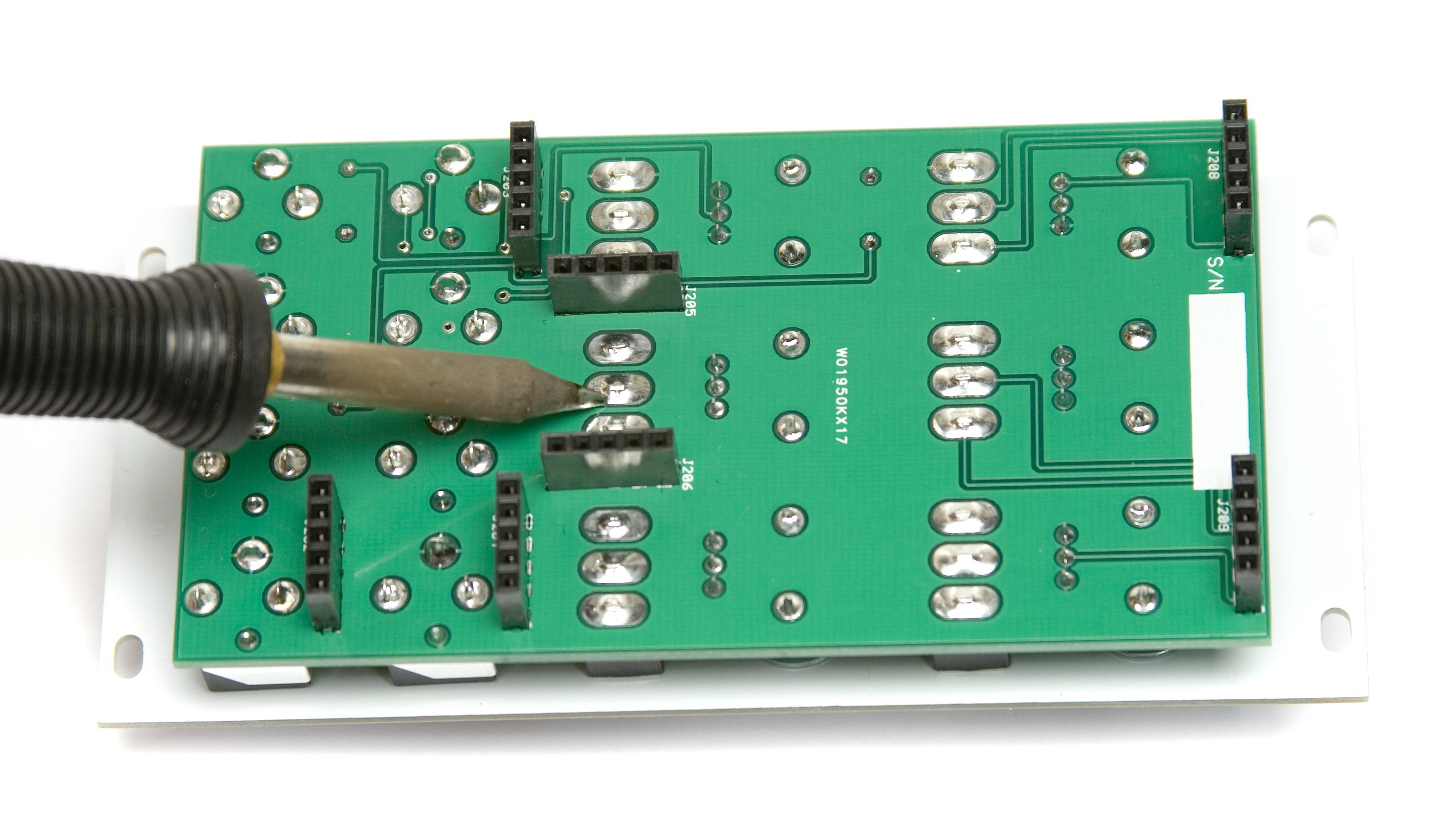
Next up, flip the board over so you are working on the back. Place the 2 pin male headers in their spots. Now flip the board back over and solder. Please be careful, as you will be soldering close to sensitive components.
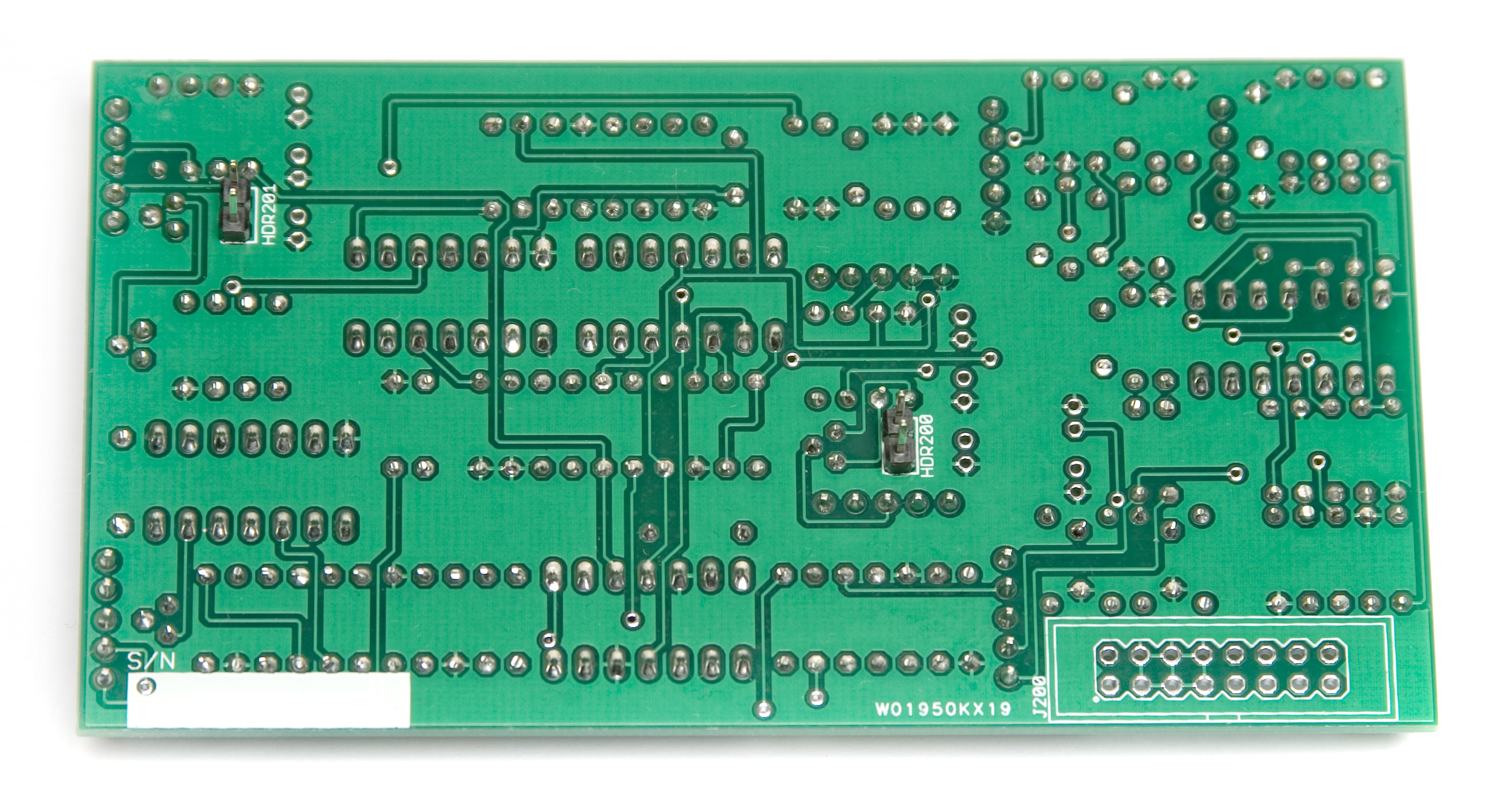
MST Dual Envelope 2 Pin Headers
16 PIN EURORACK POWER CONNECTOR
Now populate the 16 pin power connector, taking care to align the notch in the connector with the ‘notch’ (the two lines close to the board edge in the silkscreen). Then flip it over and solder.
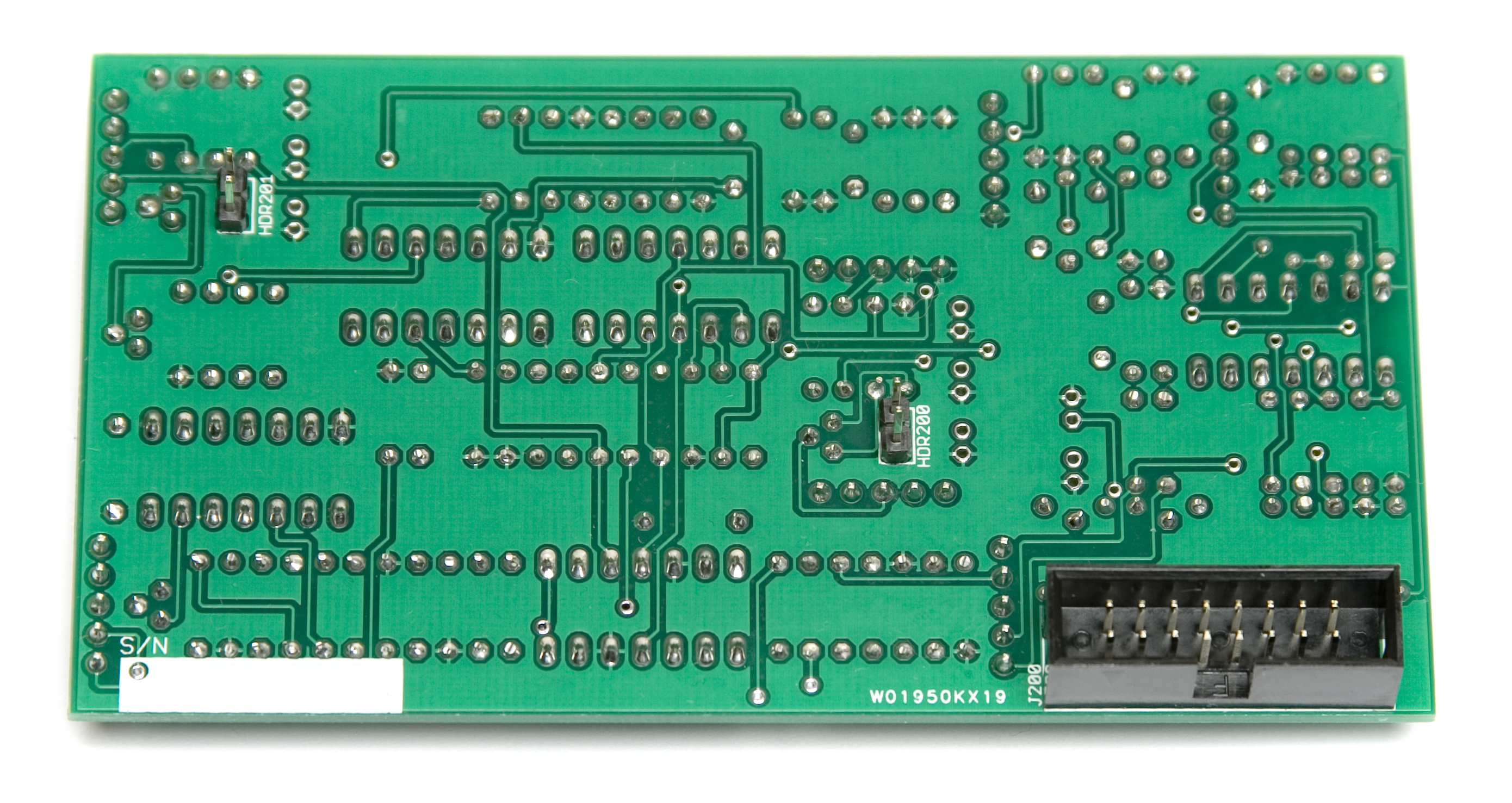
MST Dual Envelope Power Connector
ELECTROLYTIC CAPACITORS
This part can be tricky. Read through the whole section before you begin soldering!
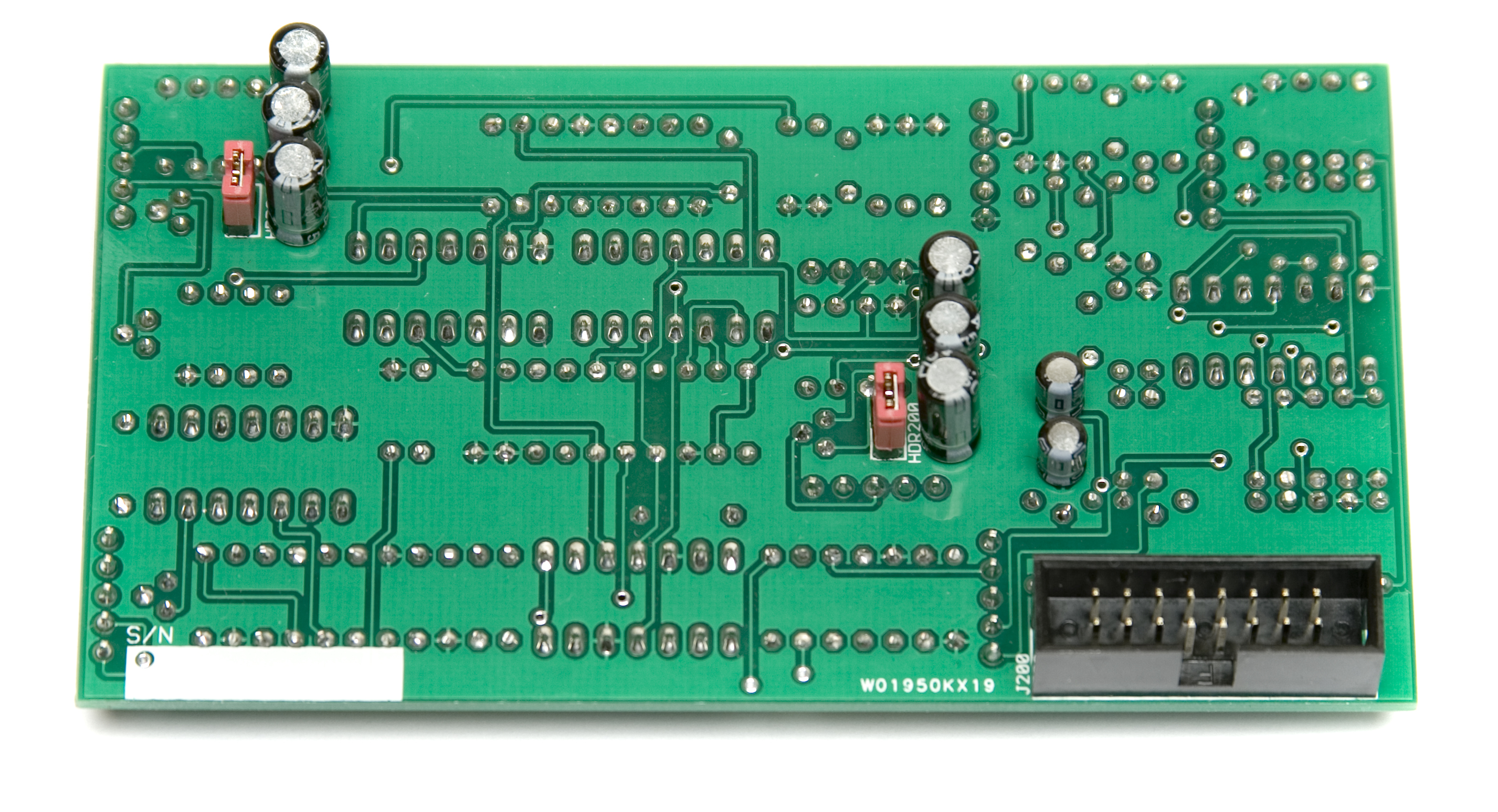
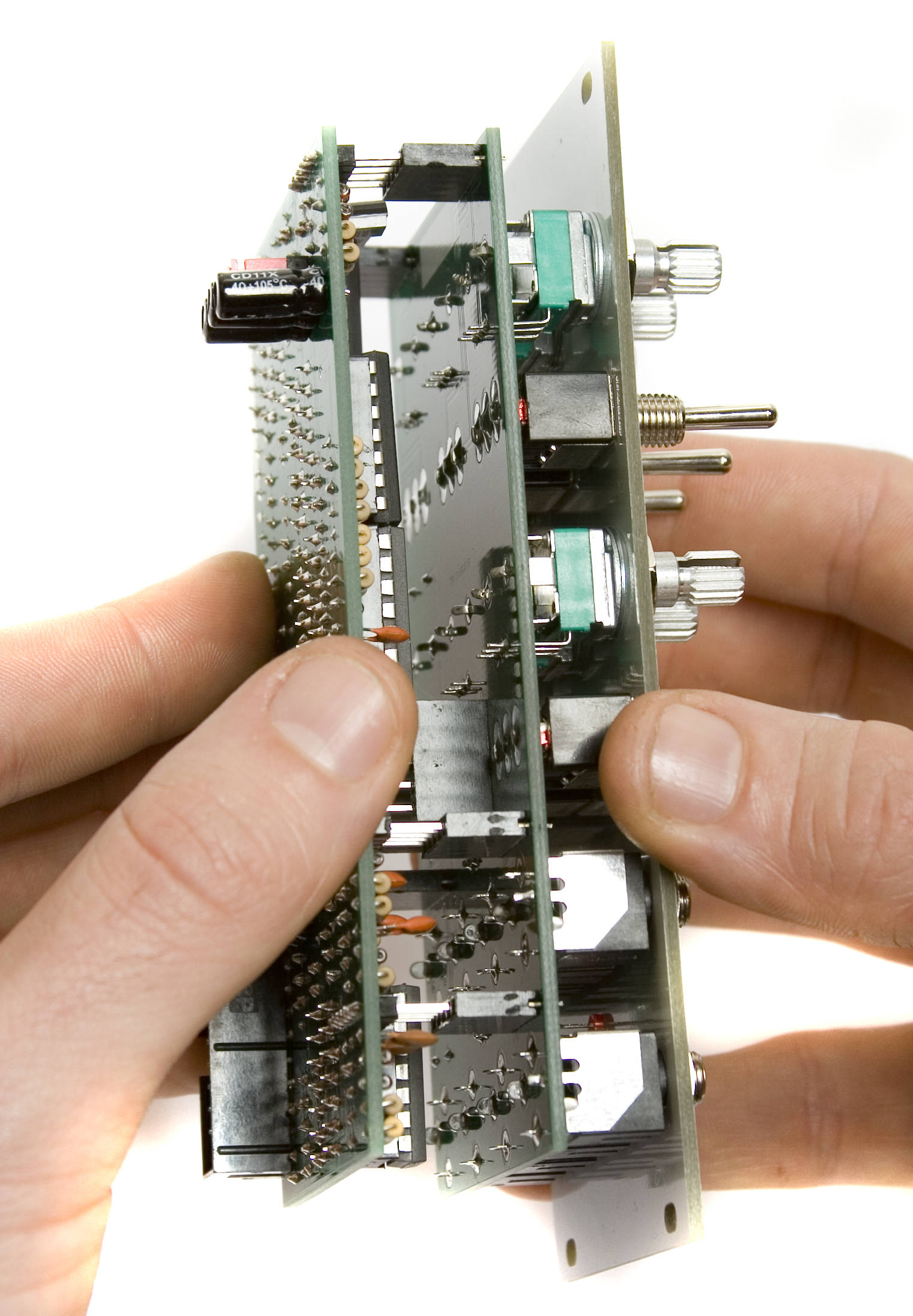
The electrolytic capacitors go on the back side of this module, due to space between the boards. To properly orient the electrolytic capacitors, look at the side of the board with the resistors, and note which solder pad has a + next to it. When placing the capacitors on THE BACK of the board, (same side as the 16 pin power connector) be sure to put the anode (+) through the proper hole. See the pictures below for reference.
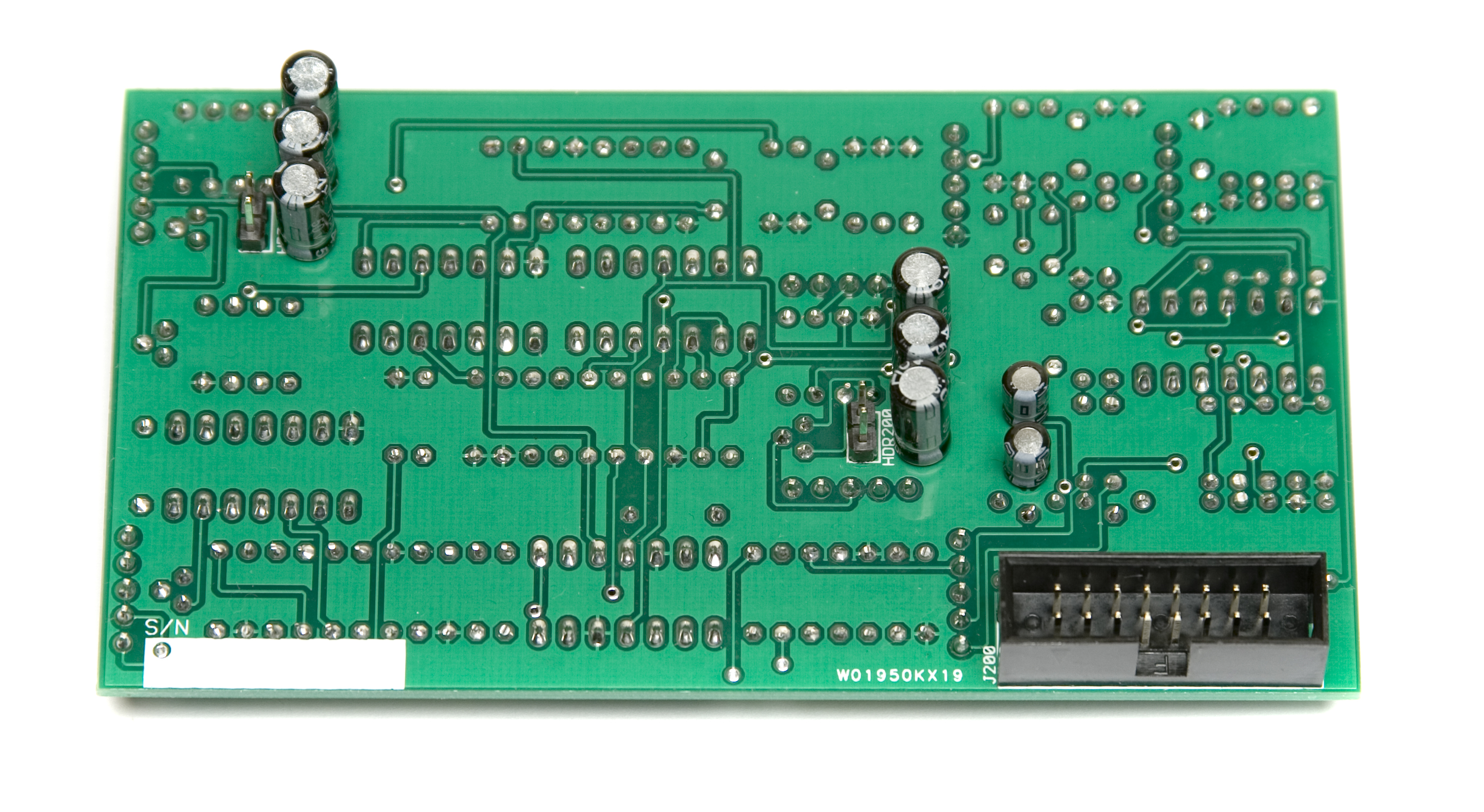
MST Dual Envelope Electrolytic Capacitors
Align your capacitors like in the photo above. All the cathodes (marked with the stripe) face the bottom of the board in the picture above. Make sure yours looks like this.
ICS AND 2 PIN JUMPERS
Next up, insert the ICs into their proper sockets by aligning the notches in the ICs with the notches on both the socket and the PCB silkscreen. Then flip the board over, and place the 2 pin jumpers on the 2 pin headers you placed earlier.(see pictures below)
Dual Envelope ICs
Dual Envelope 2 Pin Jumpers
CONTROL BOARD HEADERS
Now it is time to start on the control board. First is the 5 pin female headers. Place the headers into the board as shown below and flip over on a flat surface and solder. Then clip the leads. If you’re having trouble, you can use the trick as described above (for the male headers) to help get them soldered down. Another pro tip for perfect alignment is to place the female headers (unsoldered) on the male headers already soldered to the logic board. Then align the control board PCB to the headers and make sure its nice and flat. Then solder the headers into the control board. The two boards can be removed now to continue on.
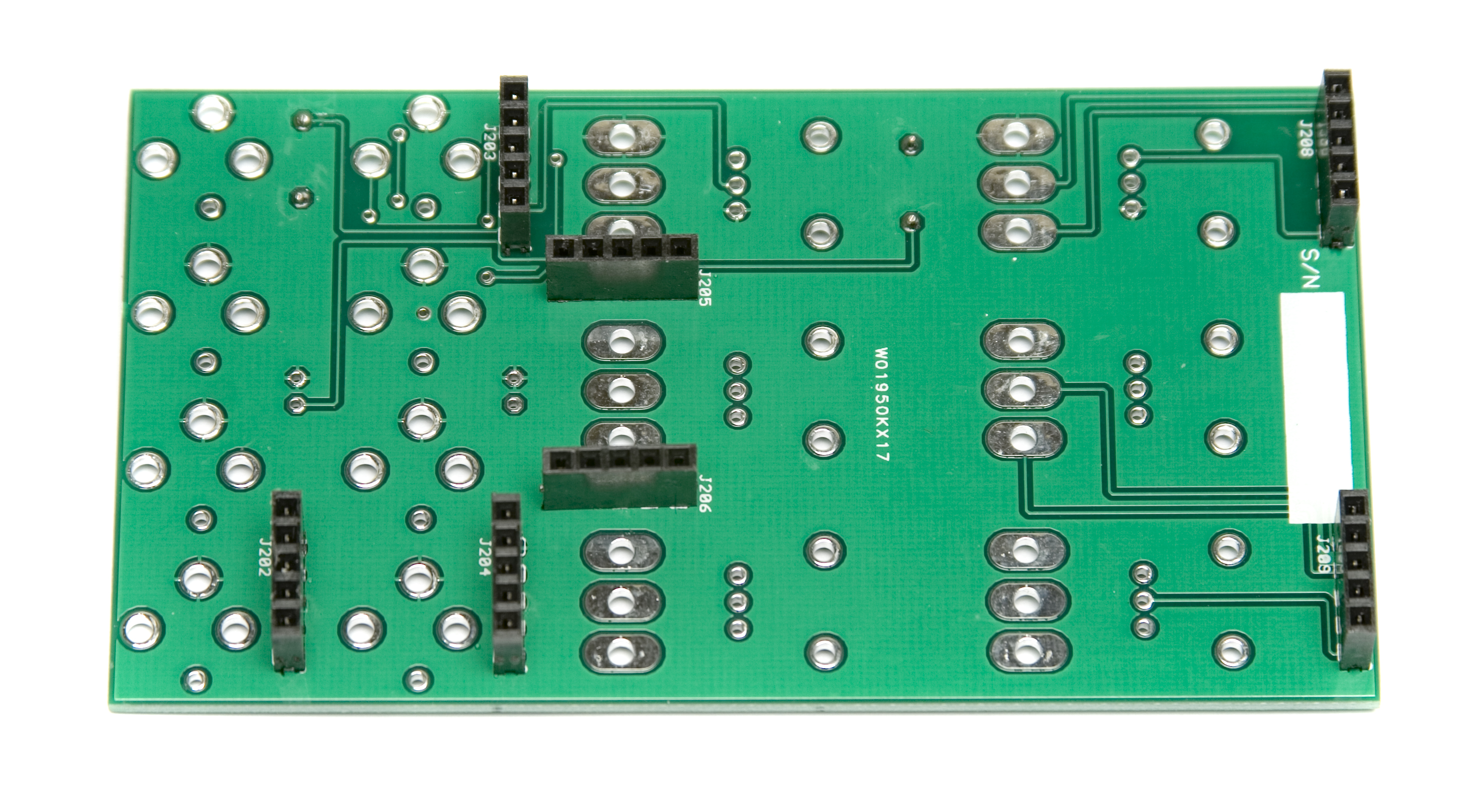
MST Dual Envelope 5 Pin Female Headers
JACKS, POTENTIOMETERS, SWITCHES & LEDs
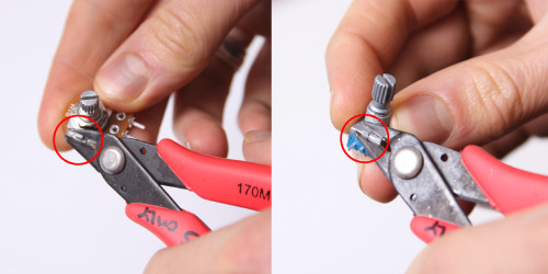
Don’t forget to cut the nubs on the potentiometers as necessary.
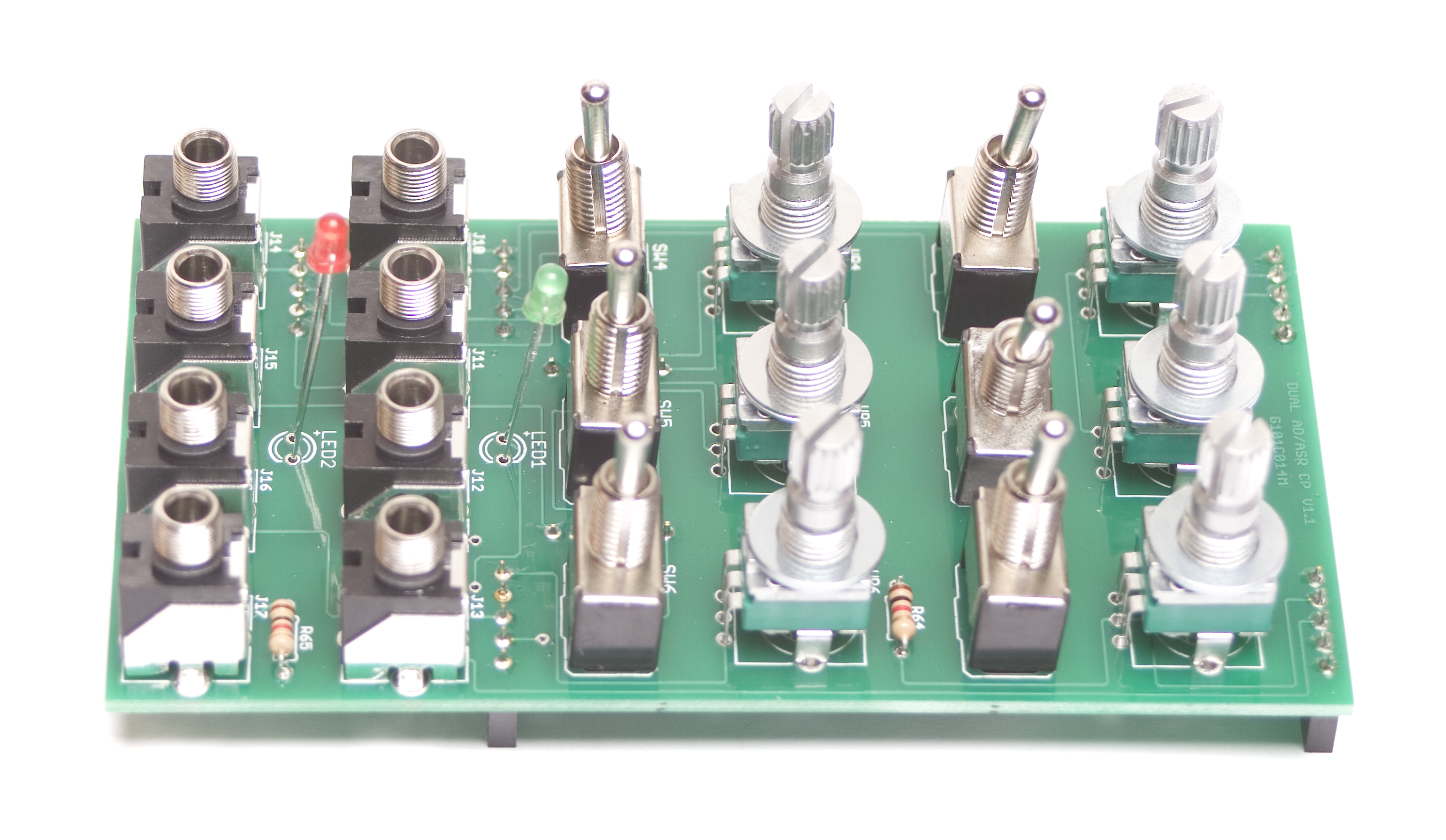
Now PLACE (do not solder yet!) the jacks, potentiometers, switches and LEDs in the circuit board as shown below. Make sure to remove ALL the nuts and washers from your switches before panel placement. LEDs are polarized components, make sure you place the anode (longer lead) into the pad with the ‘+’ marking next to it. The green LED goes in the top placement (LED1) and the red LED goes in the bottom (LED2).
Please read through the whole process before starting!
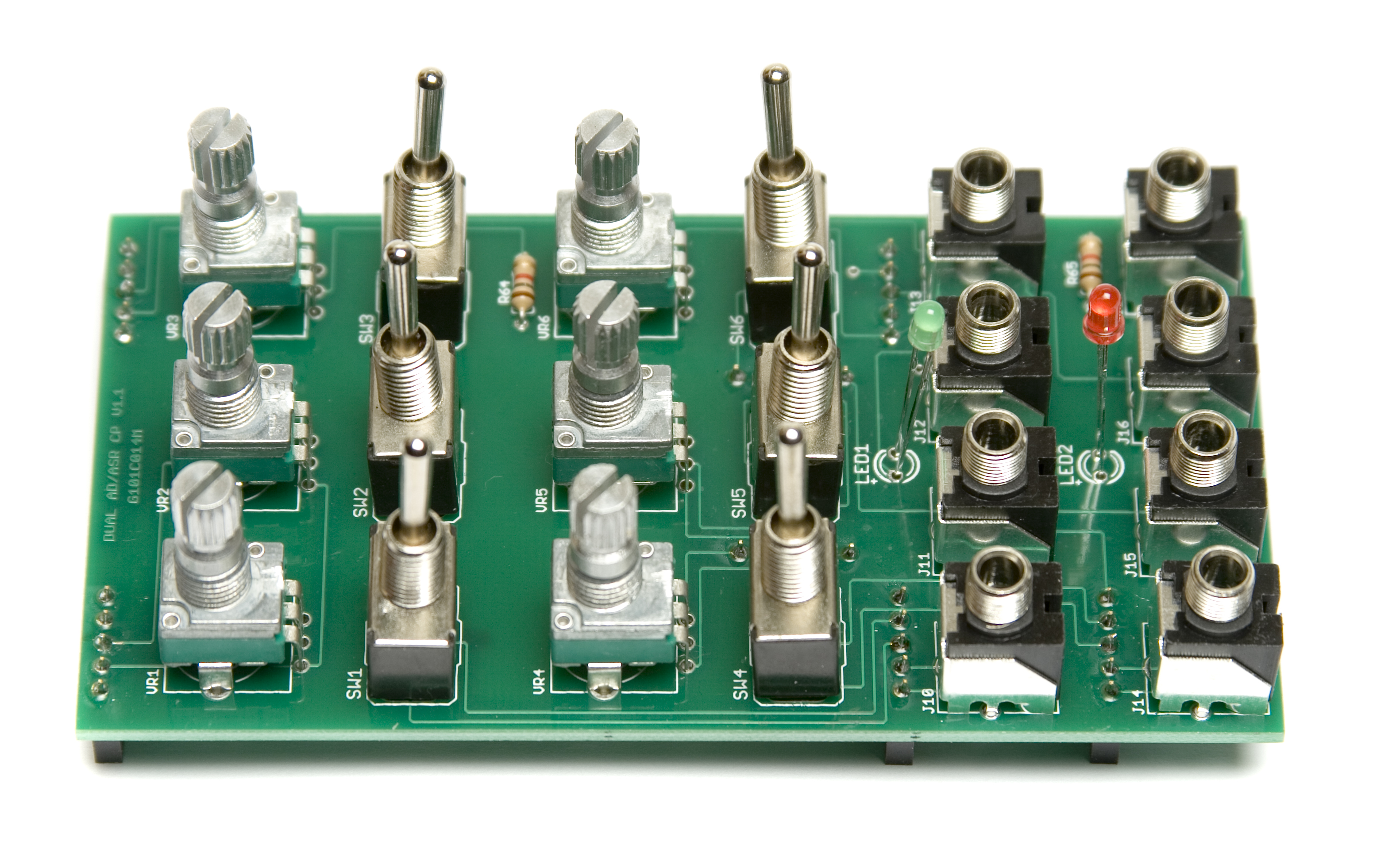
MST Dual Envelope Jacks, Switches, Pots, and LEDs
Now place the panel over the pots, jacks, switches and LEDs.
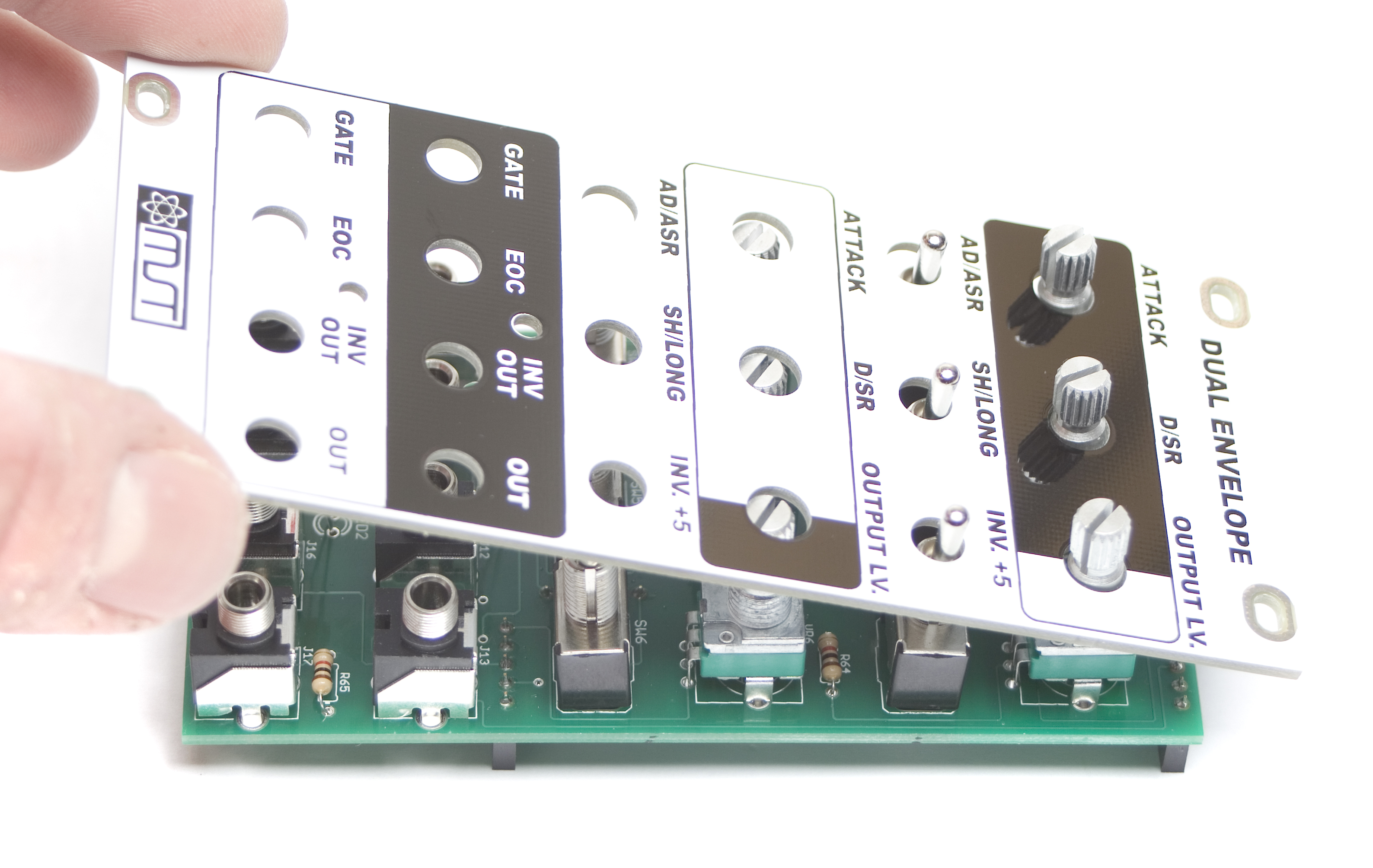
MST Dual Envelope Front Panel Placement
Fully tighten the nuts on the pots, jacks and switches. Be careful not to over-tighten!
MST Dual Envelope Tightening
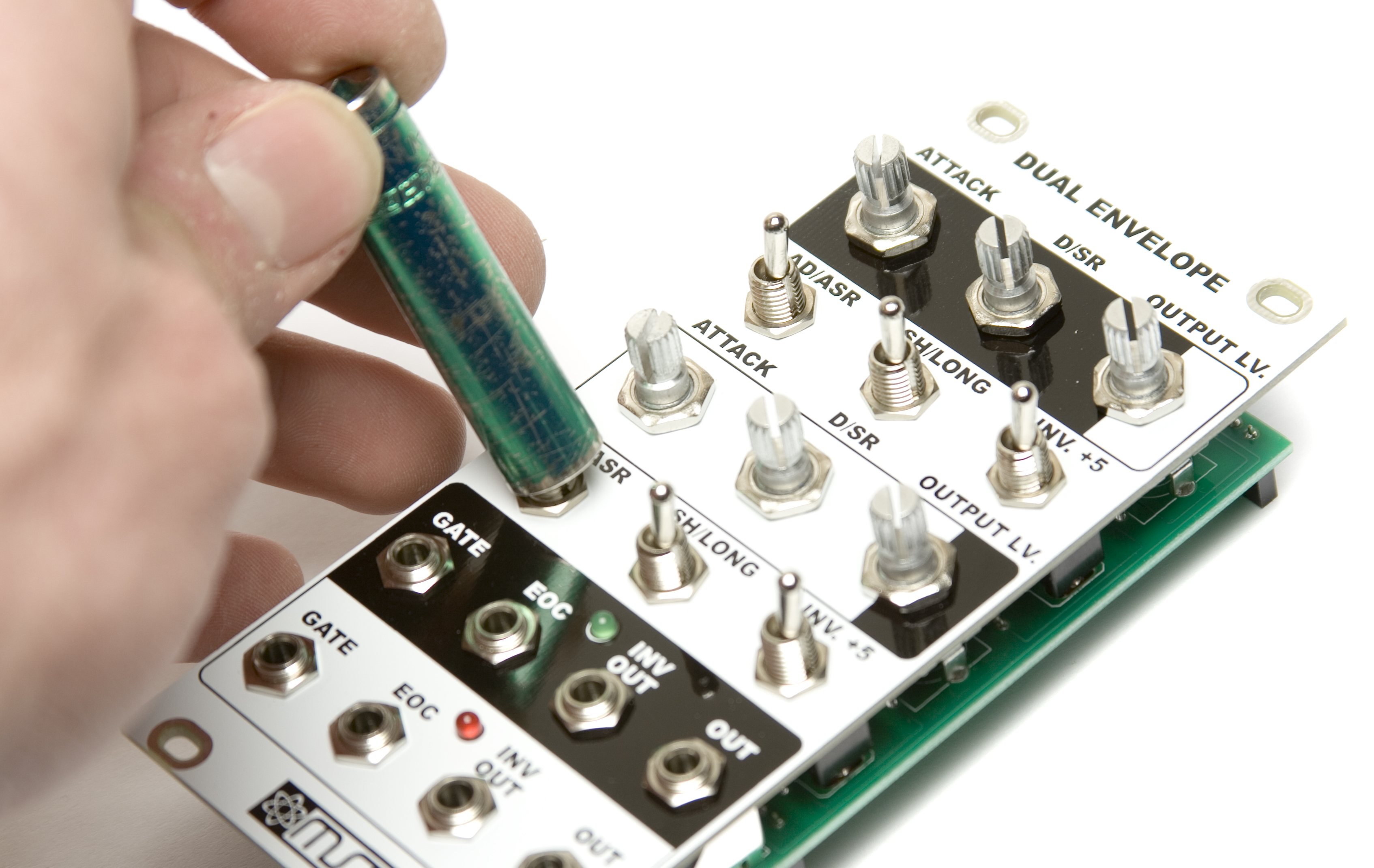
Now you will need to move the panel (please be careful and take it slow) in order to make sure that it is level with the control board. This will involve pulling the pot leads and clamps out of the board just a bit. Take your time and get this right!
Another option is to place a couple washers (if you have some extras) on the pots before placing the panel to help even out the spacing.
Optional Washers on potentiometers
Now carefully turn the board over and solder the pots, jacks and switches in place.
MST Dual Envelope Soldering
FINAL ASSEMBLY
Now Carefully! connect the two boards together and you are ready for testing! Plug your power cable into your Eurorack power supply and test away.
MST Dual Envelope Final Assembly
COMPLETED UNIT
Now you have a completed MST AD/ASR Dual Envelope that is ready to be put into your rig!
Thanks for choosing Synthrotek!
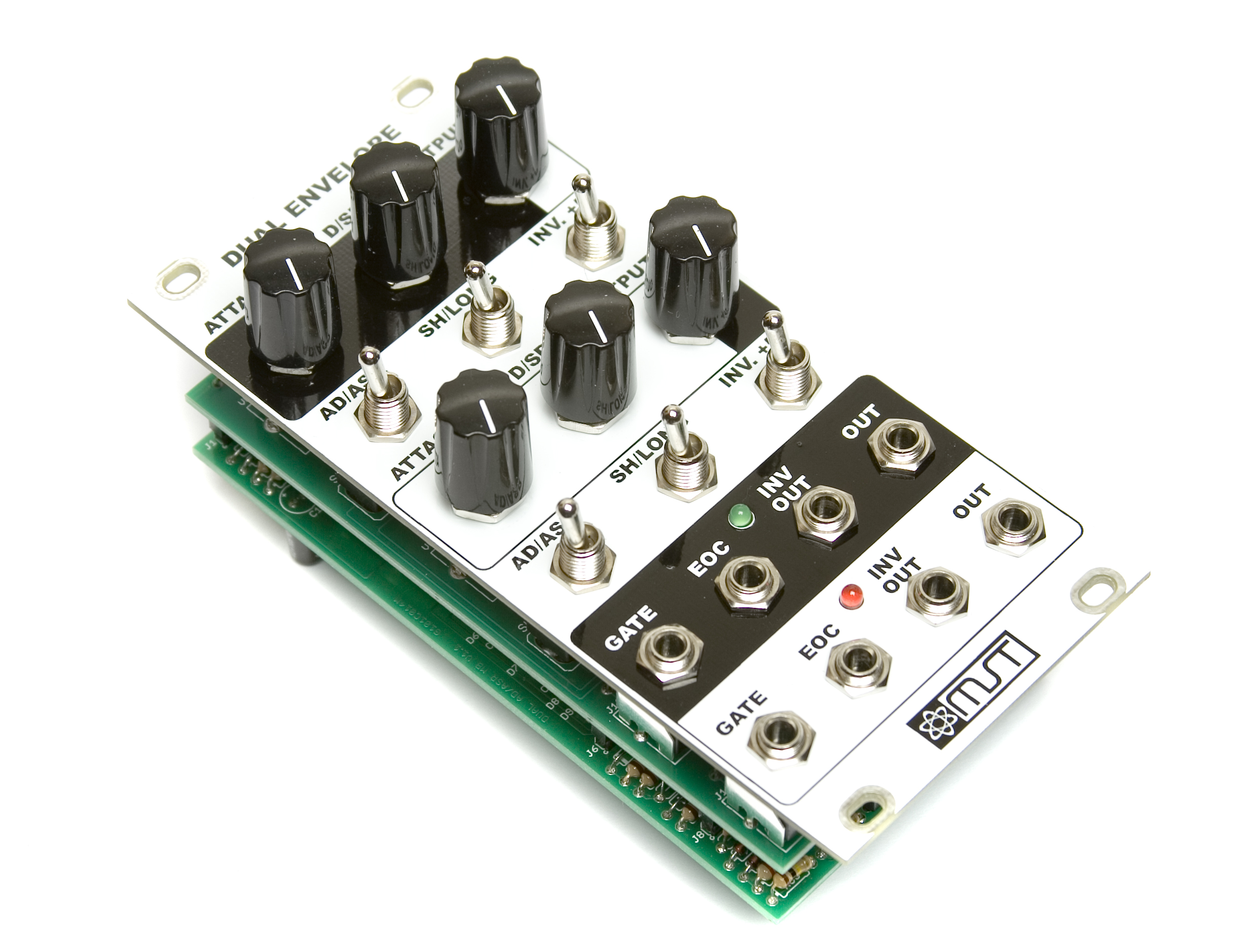
MST Dual Envelope Completed
i have issues with my dual envelope build ,but i cant find a schematic or an eagle file anywhere
Can you please send me those or tell me where i can find them
thank you in advance
Henk van den Broek
We actually don’t have schematics available for that product due to the license we have with our designer. Please email me photos of your build to synthroteksales@gmail.com and any info your having with the build and I’ll do everything I can to help you.
Is the ‘EOC’ (im guessing ‘End of Cycle’) meant to be an input? just what type of module would i plug into that? It isnt all too difficult to get my brain wrapped around, though im curious. Will this module expect a signal’s falling edge to trigger that, or is it expecting a rise in voltage to trigger it?
Okay so now that ive read the guide ill try to answer my own question. So the ‘EoC’ is actually an output, not an input. One that will send a signal voltage when the whole envelope has finished its job? Judging from what ive read this is the best interpretation that i can find. Sorry for any time you may have spent reading this, maybe helpful for others who dont read…
Hi James, the EOC will give you a trigger when the cycle ends, you can use that trigger another envelope, a drum module, use it as a clock, etc. It can be used for starting events.
Hi James, you are correct, a trigger when the full cycle ends.