


Important Links
Product Page
Store Page
Assembly Instructions
Bill of Materials
Capacitor and Resistor Lookup Guide
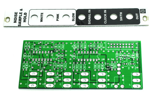
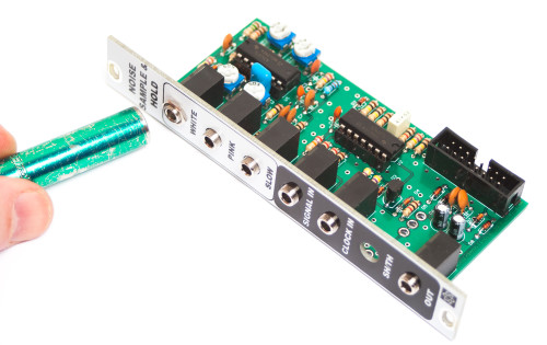
MST NOISE / Sample & Hold / Track & Hold Panel and PCB
Thank you for purchasing the MST Noise / Sample & Hold / Track & Hold Eurorack module kit! This is an intermediate build. If you feel like you can handle it please proceed! If not, get some help from a friend with experience or purchase a fully completed unit. This kit also requires the builder to use an oscilloscope and a spectrum analyzer to properly calibrate the unit once complete.
Please follow the BOM and these instructions and don’t populate from the PCB alone. Also sometimes we cannot get the exact pictured components, so please look over your parts and check the codes first.
Please note: this build MUST BE DONE WITH LEAD SOLDER.
Lets begin!
DIODES
Start with the diodes as shown below, then turn over on a firm surface to solder, then clip your leads. Diodes are polarized components so you must match the black stripe on your diodes with the white stripe on the PCB silkscreen. Please note that D4 is an SD103C diode. The S&H portion of the circuit will not work unless you use this exact diode. This diode should have a voltage drop of ~.3 volts.
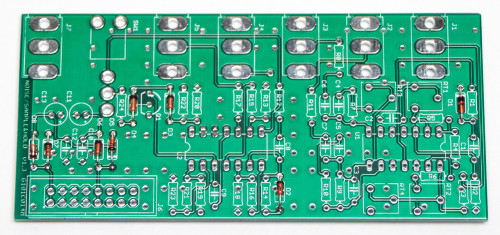
MST Noise / S&H / T&H Diodes
RESISTORS
Populate first, then turn over on a firm surface to solder and clip leads. Using a flat rigid card or another PCB can help hold the resistors in place as you turn the board over.
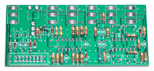
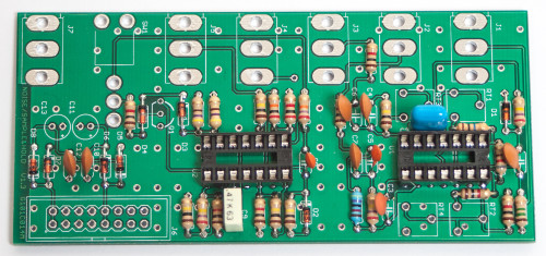
MST Noise / S&H / T&H Resistors
SOCKETS
Place the IC Sockets by aligning the notch with the notch graphic on the PCB Silk Screen. Turn over on a flat surface and solder into place.
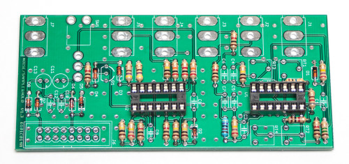
MST Noise / S&H / T&H Sockets
CAPACITORS, TRANSISTOR & TRIM POTS
Add the non-polarized capacitors as shown below. Turn over to solder and clip leads.
MST Noise / S&H / T&H Capacitors
Add the transistor by matching the flat side of the transistor with the flat side on the silk screen, turn over to solder and clip leads. Next, make sure you orient the electrolytic capacitors in correctly. The longer lead needs to be inserted into the hole that has the “+” marking near it.
Next, insert the trim pots into their appropriate spots, taking care to orient them as in the picture below. Now you can turn your project over onto a flat surface, solder and clip leads.
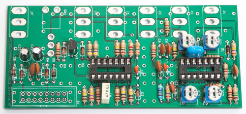
MST Noise / S&H / T&H Transistors & Electrolytic Caps
INTEGRATED CIRCUITS & 16-PIN POWER HEADER
Place the ICs in place by aligning the notch with the notch graphic on the PCB Silk Screen and notch on the sockets. Next add the 16-Pin Eurorack Power Connector in place by matching the key notch with the key indicator on the PCB silk screen. Turn over on a firm flat surface and carefully solder all of the pins.
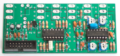
MST Noise / S&H / T&H 16-PIN CONNECTOR
JACKS, SWITCH & PANEL
Place the the jacks in and on a flat surface solder (for now) ONLY THE CENTER PIN of each jack to the PCB. Make sure the Jacks are tight to the PCB.
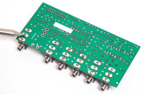
MST Noise / S&H / T&H Jack Soldering
Now place the panel on the jacks as shown below and tighten down all of the jack nuts.
Once you have lined up the panel to the board, and made sure that everything is nice and flat, go ahead and solder the remaining pins on the jacks.
MST Noise / S&H / T&H Panel Placement
Now take your SPDT switch and remove all nuts except for the last nut as shown below and unscrew that nut just as the photo shows.
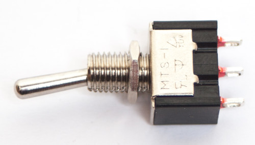
MST Noise / S&H / T&H Switch
Place the switch behind the panel and tighten down the other nut firmly to the panel.
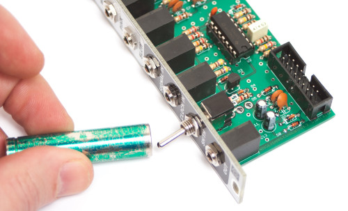
MST Noise / S&H / T&H Switch Nut
Make sure the switch is aligned perpendicular to the PCB, just as shown below.
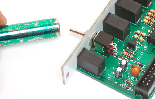
MST Noise / S&H / T&H switch alignment
Take 3 of your leftover resistor leads and make some hooks as shown below.
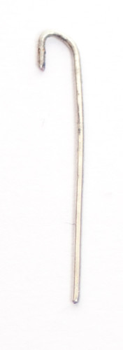
Switch Hooks
Place the hooked leads on the switch solder lugs, one at a time, and solder
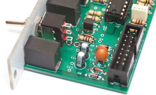
MST Noise / S&H / T&H Switch Hooks Placement
When you have finished soldering all of the hooked leads, the switch should look as it does below.
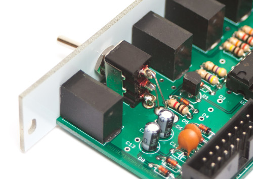
MST Noise / S&H / T&H Finished Switches
Congrats! You are now ready to test and calibrate your module. Thank you for choosing Synthrotek!
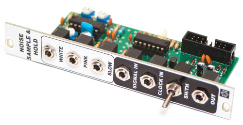
MST Noise / S&H / T&H Final Build
Noise Calibration
Roughly Center all four trim pots.
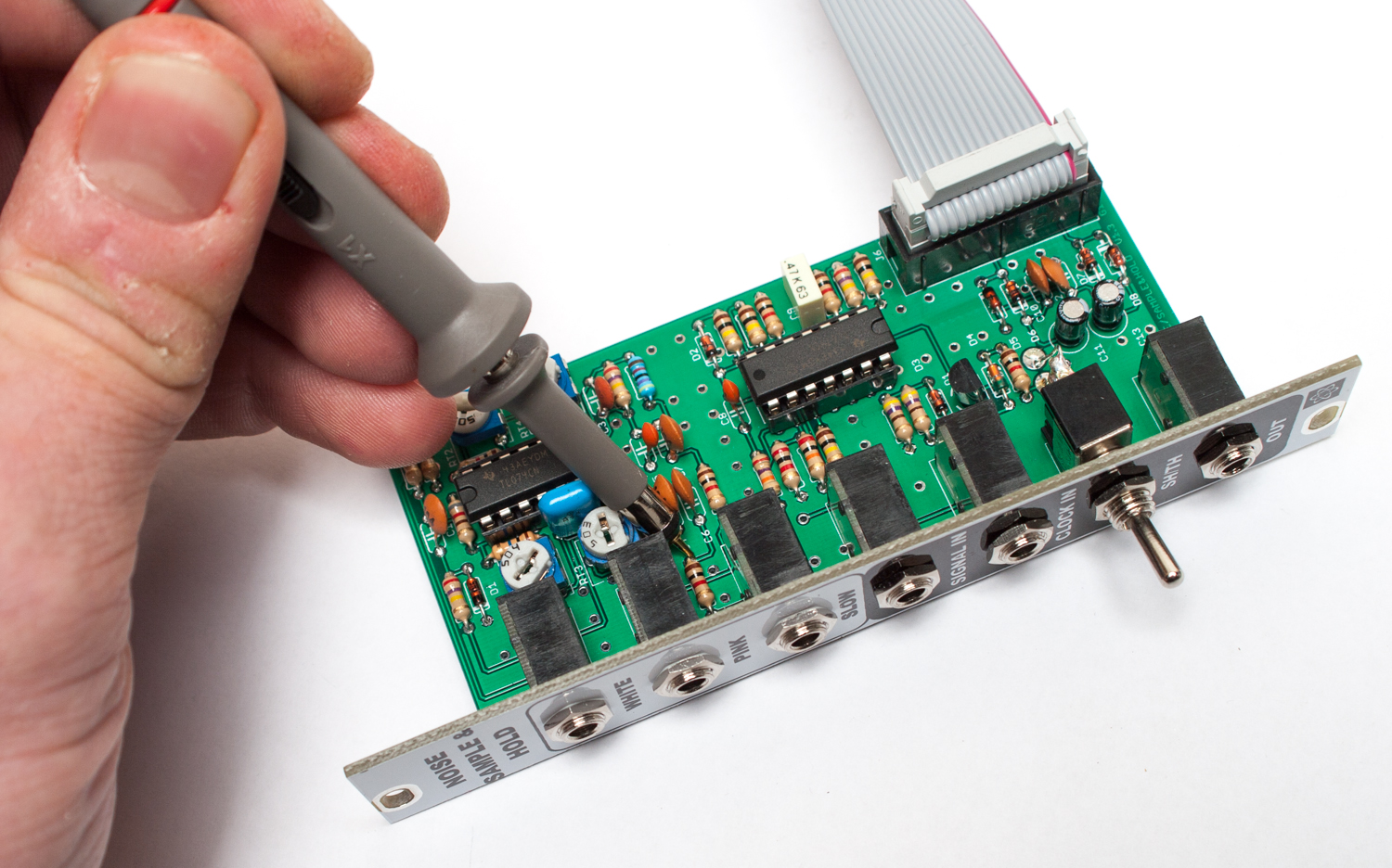
Place the scope probe on the White Noise output prior to the 1K output resistor R3.
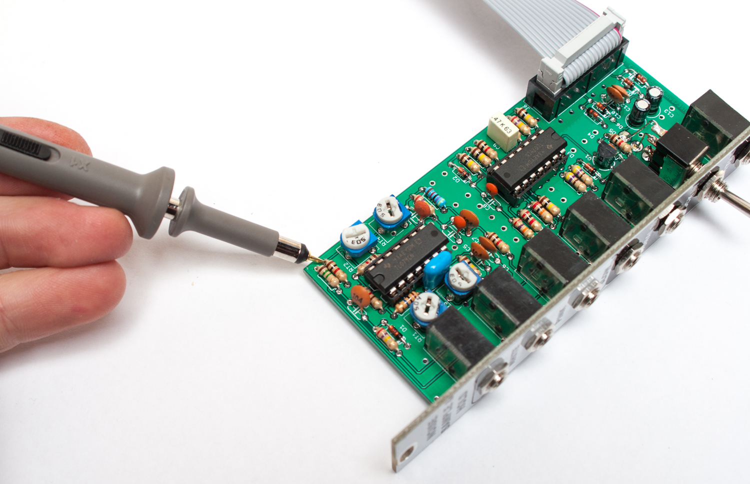
White noise test point R3
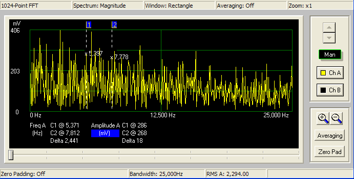
Set the spectrum analyzer frequency range to cover roughly 20Khz.
Trim the Noise Adjust RT1 until the noise spectrum is of roughly equal amplitude across the whole spectrum.
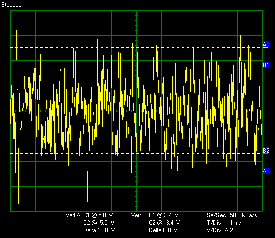
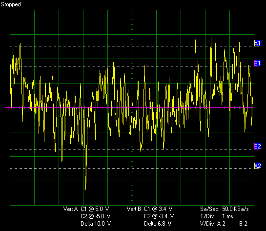
Trim the White Noise Gain Trim RT2 until the scope trace indicates peaks slightly past +/-5V output.
Now place the scope probe on the Pink noise output prior to the 1K output resistor R8.
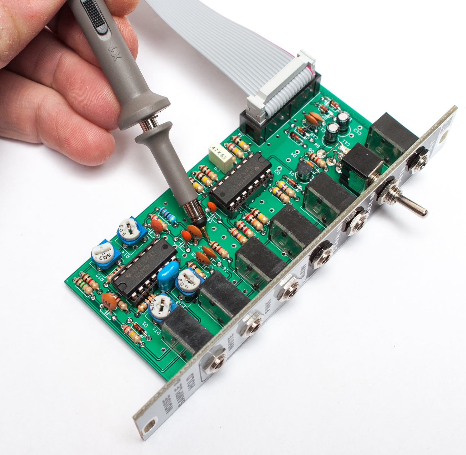
Pink noise test point R11
Trim Pink gain RT4 until the scope trace indicates peaks slightly past +/-5V output.
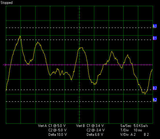
Now place the scope probe on the Slow noise output prior to the 1k output resistor R8
Slow noise test point R8
Trim the Slow random Gain RT3 until the scope trace indicates peaks slightly past +/-5V output.
There are a couple of minor details missing from the assembly instructions. First, they advise you to solder the center pins of the jacks before you assemble the panel, but does not mention soldering the outer pins. Also, the four trim pots are not mentioned. The important thing, though, is that the module works great. Very good design.
Hey Michael,
Thanks for the feedback!
We will make those changes to instructions this week.
And thanks for your kind words.
We are very proud of the way our MST stuff is designed.
-Zach