


Important Links
Product Page
Store Page
Assembly Instructions
Bill of Materials
Capacitor and Resistor Lookup Guide
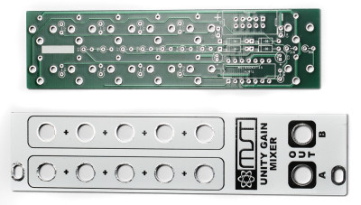
Thank you for purchasing the Synthrotek Eurorack 1U Unity Gain Mixer Module kit! This is an intermediate build as it has many stand-up resistors and tight soldering. If you feel like you can handle it please proceed! If not, get some help from a friend with experience or purchase a fully completed unit.
ATTN: Please follow the BOM and these instructions and don’t populate from the PCB alone. Also sometimes we cannot get the exact pictured components, so please look over your parts and check the codes first. Lets begin!
DIODES
Start with the diodes as shown below, then turn over on a firm surface to solder, then clip your leads. Diodes are polarized components so you must match the black stripe on your diodes with the white stripe on the PCB silkscreen.
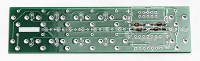
3U Unity Gain Mixer Diodes
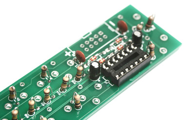
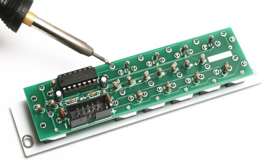
IC SOCKET
Place the IC Sockets by aligning the notch with the notch graphic on the PCB Silk Screen. Turn over on a flat surface and solder into place.
3U Unity Gain Mixer IC Socket
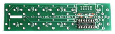
RESISTORS
There are quite a few resistors that need to be installed standing up. It is helpful to bend over one of the resistor leads first before populating each resistor. Solder and clip leads.
3U Unity Gain MIxer Resistors
CAPACITORS
Add the non-polarized capacitors as shown below. Next, make sure you orient the electrolytic capacitors in correctly. The longer lead needs to be inserted into the hole that has the “+” marking near it. Turn over to solder and clip leads.
3U Unity Gain Mixer Capacitors
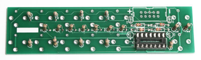
10-PIN POWER HEADER & IC
Next add the 10-Pin Eurorack Power Connector in place by matching the key notch with the key indicator on the PCB silk screen. Turn over and solder on a flat surface. Then add the IC by aligning the notch of the IC with the notch on the header and pcb silkscreen.
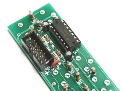
3U Unity Gain Mixer Header and IC
JACKS & PANEL
Now place the jacks on the other side of the PCB as shown below (do not solder just yet!)
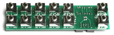
3U Unity Gain Mixer Jacks
Now marry the PCB and the Panel and fully tighten (not too tight) the jack nuts as shown below:
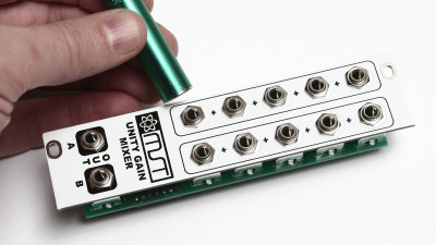
3U Unity Gain Mixer Nuts
You can now solder the jacks in place. After you have soldered all of the jacks you are ready to test your module!
3U Unity Gain Mixer Jack Soldering
If you have any questions or need help debugging, please first refer to our troubleshooting guide BY CLICKING HERE. If this gets you nowhere, please contact us by email for support. Thank you again for purchasing your kit from Synthrotek!
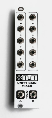
Final 3U Unity Gain Mixer