


Important Links
Product Page
Store Page
Assembly Instructions
Bill of Materials
Fuzz Face Drill Template
Schematic
Capacitor and Resistor Lookup Guide
Welcome to the Genuine Arbiter Fuzz Face Clone Kit Instructions! It’s a great circuit and it’s an easy build, so let’s get started! This kit can be purcahsed with either Germanium AC128 PNP transistors or BC588 Silicon PNP transistors.
BOM Layout

DA Fuzz Face Layout
Assembly Instructions
Attention: Changes may occur after the Assembly Instructions are created and the photos may not reflect those changes. Always use the BOM to verify the placement of components.
PCB Components
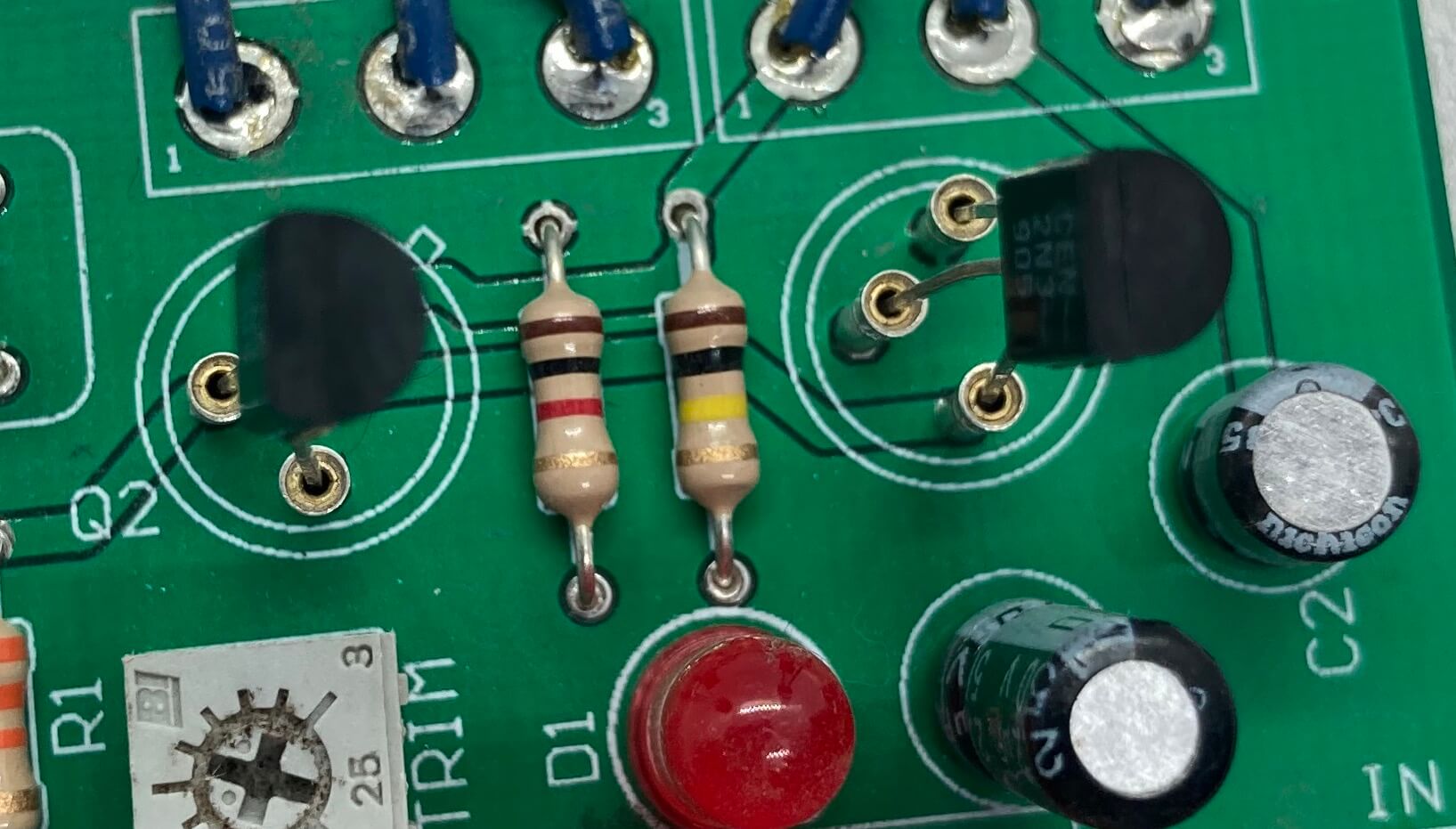
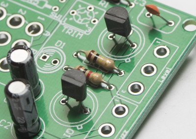
Resistors

Locate the silkscreen component identifiers for R0, R1, R2, R3, R4, and R5. Insert each resistor into the correct through-holes and solder them to the board.
Capacitors

When placing C1 and C2, use the picture above to help you position these electrolytic capacitors. Note the black band; this indicates the negative polarity lead of the capacitor. To further assist you, the PCB has a ‘+’ and a square through-hole for the positive lead and a circle through-hole for the negative lead.
C3 is a ceramic capacitor and it does not matter which lead goes into which hole.
Transistors
Make sure your transistors are oriented correctly! Each type faces a different direction!
2N3905 Transistor Orientation

Germanium AC128 PNP Transistor Orientation
FOR OLDER KITS ONLY!!
BC558 PNP Transistor Orientation
Pay special attention when placing the transistors onto the PCB. Each of the three leads has a specific function and the circuit will not work if they are placed incorrectly.
When using the silicon 2N3905 or BC558 transistors, follow the orientation in their respective photos.
Germanium transistors: Line up the little tab on the transistor with the tab on the board as shown in the first picture above. Q1 gets the lower gain transistor (if you are using Synthrotek’s transistors, it will be marked with a black dot). Q2 gets the higher gain transistor.
The trimpot has three leads. Orient the trimpot as shown in the picture above and insert the leads onto the PCB. If the leads are bent, gently bend them to conform to the through-hole layout on the PCB. Once the circuit is completely built, you can adjust this trimpot to color your sound to your needs.
That is all for on board components.
Wired Components
Potentiometers
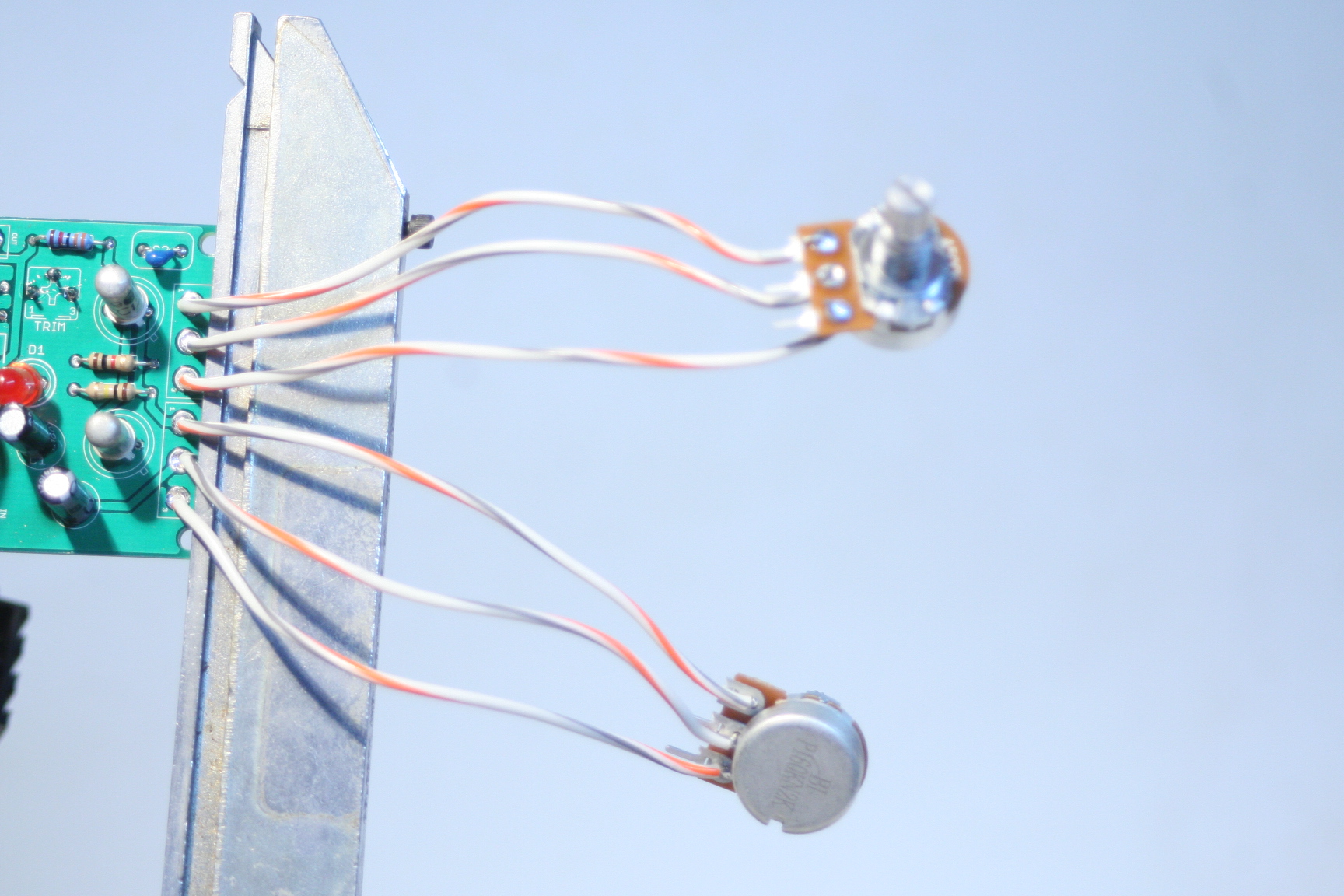
Wire the pots exactly as shown in the picture above (the top one is the A500k and the bottom is B1k). Make note that the B1k pot is reversed from the orientation that most of our pots use.
We suggest soldering wires to the potentiometers before attaching them to the PCB. Having to de-solder a too-short wire from the PCB is an extra step that can be avoided. As always, use more wire than you think you will need; wire can always be cut.
When installing the pot, some pots come with nubs near the shaft that may get in the way of installing the circuit into a case. Check for a nub and clip as necessary.

Don’t forget to cut the nubs on the potentiometers as neccesary.
Input/Output Jacks and Power Jacks
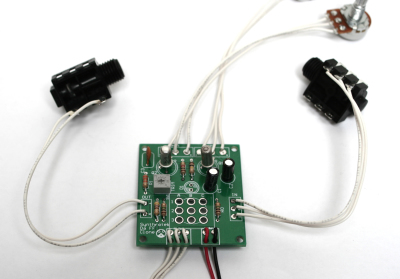
The ‘In’ Jack of the Arbiter Fuzz Face Clone circuit uses a 1/4″ stereo jack which turns off the power sources when nothing is plugged into it. When you plug a mono plug into the jack, the circuit receives power.
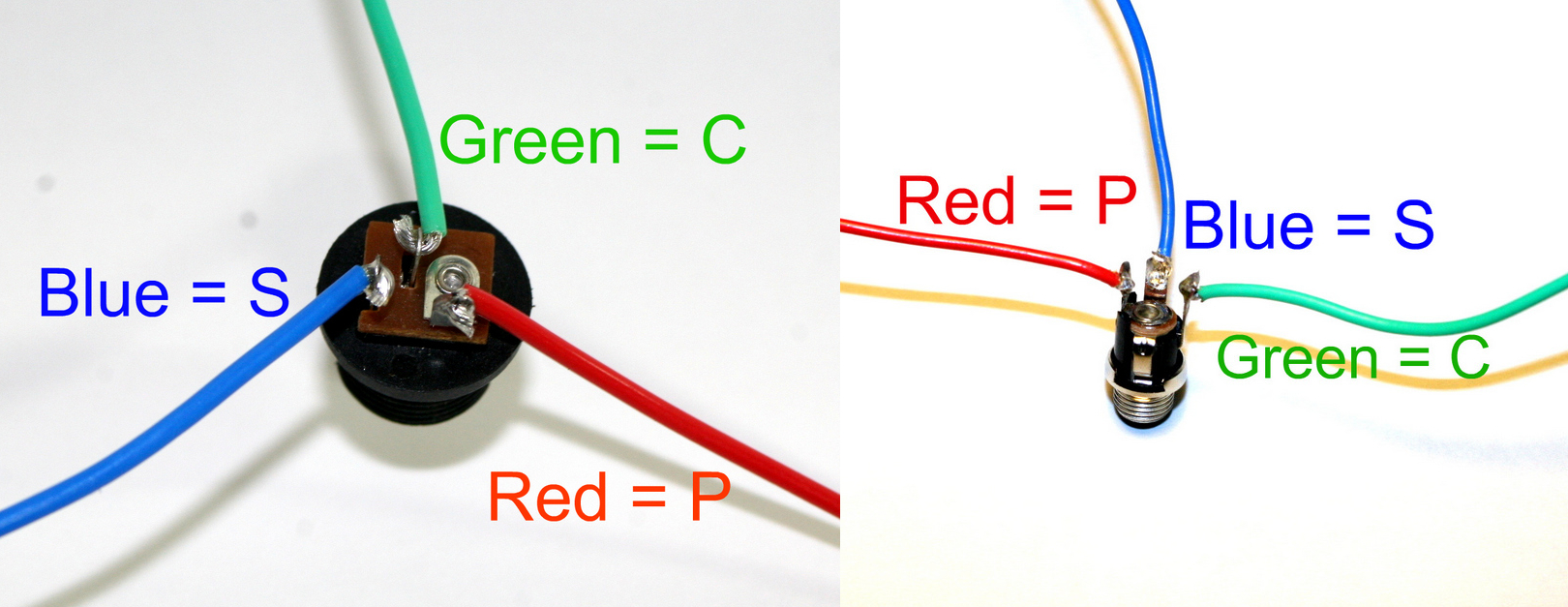
Stereo jacks have three solder lugs for the 3 different parts of the stereo signal: Tip, Ring, and Sleeve. On the PCB, they are identified as ‘T’, ‘R’, and ‘S’. Attach each solder lug on the jack to their respective PCB connection. Make sure to use the solder lugs as pictured above.
On the other side of the board is the ‘Out’ PCB connections. They are marked ‘T’ and ‘S’ for ‘Tip’ and ‘Sleeve’. Mono jacks only have these two connections, so they are easy to wire up.

The 9V battery jack is easy to put onto the PCB. Take the red wire and insert it into the square through-hole with the silkscreened ‘+’. The black wire goes to the circle through-hole marked with a ‘-‘.
DC Jack Pinout
The DC Jack has three solder terminals that connect to the PCB. Use the picture above and the silkscreen on the PCB to place the wires correctly. The DC Jack allows you to power your circuit with a wall wart and disconnects the 9V battery from the circuit, saving money on expensive batteries.
NOTE: please remember to use a 9 volt center positive power supply. Using the incorrect power supply polarity will damage your circuit.
If you do not want to install the 9V DC jack and only install the 9V battery clip you will have to short the S and C pins for the 9V DC Jack like shown in the picture below*.
* Your PCB may not look exactly like the photo, that is ok. What is important is that you short the same pins as shown in the photo.
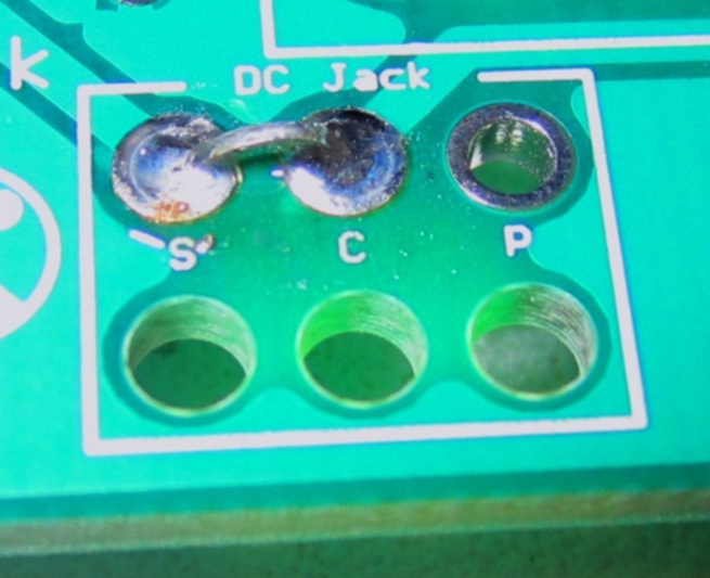
Short these contacts to get the circuit to work without the 9V DC Jack
LED
Insert the LED through the plastic insertion mount (if needed) and solder wired leads to both legs. Connect the wire leading from the flat side of the of LED to the solder pad on the board that is closest to the flat spot on the silkscreen. The picture below shows the flat spot (although the led is board-mounted). You may omit wiring the LED and mount it directly to the PCB. The photos below illustrating stomp switch wiring show the LED installed in this configuration.
Stomp Switch

Stomp Switch Help
Line up the number code from the switch to the board exactly how it is labeled in the picture (above and below.)
Make sure the flat blue side of the stomp switch is facing up when comparing it to the picture below. Either Blue Side will work fine. AND YOU CAN MOUNT THE STOMP SWITCH DIRECTLY TO THE PCB IF DESIRED.

Stomp Switch Help

Stomp Switch Wiring
Biasing Instructions:
Power on the pedal and insert a cable into the input jack. For the circuit to be optimally biased, the collector of Q2 needs to be at 4.5 volts. (When connecting the Arbiter Fuzz Face Clone circuit to your multimeter as shown in the photos below, your meter will read -4.5V.) The 20K trim pot is used to dial in this value. All you need to do is connect your leads to a ground on the PCB and the collector of Q2 to get this reading.
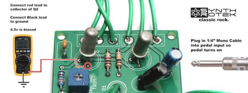 Arbiter Fuzz Face Clone Biasing Guide
Congratulations, that’s the end of the instructions for the Arbiter Fuzz Face Clone circuit! If everything is wired/connected properly, you should have a fully functional fuzz pedal. Remember to adjust the trimpot to get the sound you want from your new pedal and have fun!
hey send me a link to where i can purchase the kit for this
http://www.synthrotek.com/store/-c-36.html?osCsid=3400121e83b03f43abd43bd94be6600b
awesome kit. can you please post the resistor values for r0, r1, r2, r3, r4 and r5, as well as c1 and c2? cheers
I figure c2 to be 22uf, and c1 to be the 2.2uf cap
Ah, there it is, it’s in the bill of materials.. awesome.
http://www.synthrotek.com/kit-assembly-instructions-2/effects-assembly-instructions/genuine-arbiter-fuzz-face-clone-kit-instructions/arbiter-fuzz-face-clone-bom/
can the wires on the dc jack be switched in order to make it center negative instead of center positive? if so, i could use it with my pedal power without having to buy a special power cable. thanks!
Hi Zoran, does this do it:
http://www.synthrotek.com/kit-assembly-instructions-2/effects-assembly-instructions/genuine-arbiter-fuzz-face-clone-kit-instructions/arbiter-fuzz-face-clone-bom/
Thank you for your comment!
@Stephen
Unfortunately no. Given the interconnections of the DC, input and output jacks this will cause various different issues depending on the actual source. For example if the source supply is shared with another circuit the act of connecting a reversed Fuzz Face and another pedal would cause a short circuit in the power supply.
This will not eliminate the issue unless the power supply plugged in the adapter mentioned is a separate for the one supplying power to the rest of your components.
Is the box not provided? I can’t find any reference to the housing or box enclosure
Boxes or enclosures are only included with our kits that specifically state “with case” or other similar wording. Many of our customers prefer to place their DIY projects in their own, often unique enclosures. We are in the process of matching each kit to a case and a recommended drill pattern for that case. Once that is completed all our kits will have a “with case” purchase option.
Is it possible that the R1 shown in your photos is a 33 ohm resistor? I believe it’s supposed to be 33K ohms.
My mistake. You’re using a 5 band resistor.
Mike, That’s correct, R1 is a 5 band 1% resistor showing orange orange black red which is 33.0k and the tolerance band is brown indicating the 1%.
Is it possible to install a external 10k trim pot and is the pot a A or B taper?
Will a standard 5% resistor work if I find one that is 33.0k give or take 1%? Will a 10k log taper multi turn pot work mounted with a knob instead of the trim pot? Thanks in advance for your reply.
Hi Vince, I think that could work, and no it does not have to be a trim pot, that will work fine, thanks!
B – log thanks!
Yes and B, thanks!
A few questions…I built this and the whole circuit is extremely quiet, even after playing with the trimpot (volume is normal when bypass switch is enacted. My kit came with a red LED instead of the green one pictured. Does it matter which way the LED is positioned? After completing the circuit, the LED would not come on, even after resoldering it both ways. Like I said, my output is extremely weak, even with a brand new battery.
Hey Admbmb, there is certainly something wrong, it would not have a weaker output. The Red LED will not affect the circuit, however LED’s are polarized, so it does matter which way they are connected to the circuit. The Shorter lead on the LED is Negative and the Cathode, the Longer is Positive and the Anode. The PCB has a + and – where the LED is positioned. Also the Trim pot will affect some things, but overall it biases the Transistors, if you have turned some and the output is still low, I dont think that is the issue. Can you confirm that you have your Transistors are aligned properly? Also, are there any other components that you may have reverse polarity on? Let me know if I can help further. We can offer repair services if need be.
I have the same situation as Admbmb. Normal bypass, weak output with 3DPT switched on, no LED power. Is the DC jack essential to the circuit? I haven’t installed it. Is there a schematic I can use for troubleshooting?
Hi guys, YES the DC jack is essential, it is part of the circuit and has to be installed, please let me know if this fixes it.
Thank you. I should have seen that. For those wanting to go battery only, and not include a provision for using a DC jack, it’s necessary to connect/solder a jumper from S to C in the area of the PCB where it says DC Jack. I just tested this and now I get the LED and Fuzz, just running off a 9V battery.
Thanks Mike, this will help a bunch for folks. We mention this on a couple other kits, but not this one… 🙂
@Admbmb
So…I had no markings on the PCB indicating which side of the LED mount is + or -. Is the flat side of the LED supposed to correspond with the flat side picture printed on the PCB? I’ve had no luck with the LED lighting and have installed it both ways. I was able to get a fuzzy tone, but by weirdly lowering the level pot instead of raising it (and with the LED mounted with the flat side opposite of the picture on the board). I’ve checked, double-checked, and then whatever 20X checked the instructions and can’t figure what the deal is. I also installed the DC portion of the circuit and have tried it with a battery and with the adapter. Let me say that I love the price on this kit…love your site…and would love to see you have more kits (in which I would buy). Love to see an Octavia, Tonebender and Rangemaster kit.
Hi Admbmb, the Flat side does correspond to the Flat picture on the PCB. If you switch the two outermost leads on the pot the pot will function as you like, that is just a wiring issue. The LED should be mounted on TOP, but if you get the polarity correct, it really wont matter, and should work either way. So the pedal “works” just no light out of the LED? Perhaps there is something wrong with the led…? Thank you for the suggestions, we will certainly have more kits soon, thank you!
@Admbmb
@vince
Did the 10K B-log taper pot end up doing the job? I just saw your post and it looks like a good idea. I haven’t started the build yet and am just working out my controls.
I just assembled this board and it sounds just like I imagined it would. The Fuzz and Level both work to produce a wide range of fuzz tones with that unmistakeable Germanium seasoning. On my working board, the Fuzz pot works backwards, so as I turn it clockwise, it lowers the output. As Admbmb has noted, my LED does not work. I wired it as per the diagrams and put the positive lead into the square + hole on the board. I believe I probably need to check the wires to the DC adapter and swap C and S. Will report back if that works. Again, this is a great kit and provides the tone as expected, even for a novice electro-head like me it was a simple build!
Hi Syphonear, really glad the pedal sounds to your liking! You can swap the two outermost pins on your pot to reverse the backwards issue. Yes please check your wiring, or shorting of the DC jack, it is essential to the circuit. Thanks again!
Thanks Steve, I am aware of the need for the LED in the circuit…but honestly, it sound great without it right now. I will swap the pot wires and that should do it. Just a side note, I played in the 1960’s and used the old Maestro Fuzz Tone by gibson. In resurrecting the sound of that era, this is a faithful replica of that “sacrosanct” tone.
@Syphonear
Yeah, no worries about the LED, it should not affect the sound. I meant that the DC jack has to be installed or the PCB shorted for the LED and pedal to work as described. If it works, rock it! Thanks again for the kind words!
Yeah…thanks for all the help. Fuzz works great. I’m sure it has to do with the choice of transistors and how I have it honed in on the bias with the trim pot, but this completely slays the real germanium fuzzface that I own. Its just a brutal blissfull bloom of fuzz that cleans up nicely with the volume knob. Great work…had a blast. Will def be building another one.
Is the resistor for the led soldered to the board? Or is it soldered to the led?
Hi,
All soft components such as resistors and capacitors are soldered to the board.
Which resistor is for the led?
R4?
@Kenneth B
Yes, connections around the LED is that the pin on the flat side of the LED goes to the center pin of the 3pdt stomp switch and the other end goes to the resistor R4, and resistor R4 goes to ground.
I wired up everything per your instructions. I powered it via the DC jack. When I turned it on the led came on, but there was no signal. Then the 500k pot started smoking, so I turned it off. Also the battery clip didn’t work.
Hi Kenneth, did you use a 9V center POSITIVE ac adapter? May be the issue. Can you send me any more info? Super sorry!
I removed the dc jack and I shorted the s and c pins. The fuzz works now, but only if the 500k pot is removed. I tried using a different 500k pot, and I got the same results. It seems like it’s grounding out when I connect the 500k pot. I checked all of my solder joints and none of them are touching.
Hi Kenneth get me an email if you like and I can figure out this specific issue. It sounds like the DC jack was wired incorrectly. I have never had a pot smoke (ha ha), so something most likely got damaged. We will figure it out.
My email is optimusdime@hotmail.com. I can send you some pictures of the circuit if that helps.
Hey guys,
just as a cool tip, you could put a simple SPST switch betwween S&C connections from the DC jack for adding a convinient ON-OFF funtion.
Cheers
hey there,
I used the fuzz face PCB with very good results. But, i want the led very low energy consumer, so i add a 47 k resistant to it before i put it in the PCB.
So….I wonder if one of the resistant in the PCB its dedicated to regulate the led diode. may be r4???…the idea its to change the value of this resistant to 47k and avoidme the job to add a resistant to the led….
please let me know, i really apreciate your help..
Hi Cristian,
For the Fuzz Face, R4 is the resistor for the LED.
That would certainly work, though the when you don’t have anything plugged into the Input and the stomp-switch in Bypass mode the pedal doesn’t consume any power.
Dear Steve
Me again, i had a little problem… as you know, the synthrotek germanium daa fuzz are negative ground. For this one in particular i just using it with baterry power source. It function flawless and no problem at all individually.
BUT when a conect the fuzz to a fully functional synthrotek RAT clone, positive mass, powered with a separate power souce it comes a problem;
when I put the RAT first and the daa fuzz second in the line to the amp (The fuzz conected after the RAT), sounds flawless, bypass and both effects operating together with no problems at all.
THE problem, the strange problem, its when i put the germanium fuzz first before the RAT… in this case the stuff does not sound at all, totally death. But more important too…they dont soun even when i put both of it in true bypass mode…very very strange….or may be..very misterious…:O)
Unfortunately fuzz first and RAT after it is the configuration I would like to have, in order to modulate the fuzz treble with the rat and get a more modulated fuzz sound.
So, may do you figure out why this happens….and how to fix it?
I have the impression that the matter relates to the different polarities, that sound logic… but why work in a way, and do not in the other way? …..at this time, really a big mistery for me….
Some tips……y used an aislated plastic jacks for input and ouput in the rat…and do not remember that they was conected to the chasiss…..in deed, y dont remember that any part was conected to the chasiss…..may be the power jack???…..But its naturally do not generate hum or excesive noise…so i dont bother for that…
But, for the fuzz, in deed after first test, it have a loud hum that disappearalmost complete when y conect the sleeve of one of the plastic aislated jack directly to the chasiss using a soldered cable……Any way, when i used a switchcraft cain of jack…it automaticly conect to the chasiss because have a metal contact with it and no sound at all…but here born a secondary cuestion…when we use plastic aislated jacks in your effects, its a must to conect the sleeve of this jacks jacks to the chasiss??
well..thansk for your time, and y Really appreciate your help. Please let me know at my mail because the sistem so not warn me when i get an answer.
Cristian
@Cristian
huuu…a mistake….the fuzz have the positive ground, and the rat have the negative ground…the problem its steel the same.
Hi Cristian, are you powering them from the same Power Brick/Wall Wart? The Fuzz Face would need its own 9V center Positive power supply.
I just purchased this kit about a week ago, and I have a question about the power supply I need. The assembly instructions state that it requires a center positive power source. I have a planet waves 9v adapter for boss and similar pedals, but that one won’t work right? Do you have any recommendations? I’ve been having trouble finding an adapter that would power this pedal.
About the second stomp switch picture, does it matter which flat blue side is facing up?
Hi Jordan, either blue side will work the same. Great question, should have had this on the instructions a long time ago!
I recently finished building this pedal — when I first tested it out, it sounded great. Exactly what I was hoping for. However, the LED wasn’t working. I am pretty new to soldering and didn’t realize the polarity of the LED mattered. In the process of removing the LED, I think I must have damaged/overheated the board, because when I finally got the LED working and re-tested the pedal, it sounded screechy and thin— in a word, terrible. So now I have a basically unusable pedal. It is for the most part my fault, but I think it would be very helpful to include a quick mention of how to install the LED, so that beginners can avoid the mistake which I made. Sort of disappointed.
Hey Tim,
Sorry about the confusion on the LED mounting, getting the instructions fixed is happening soon. Thanks for pointing it out to us! As far as why it suddenly sounds screechy, there are a number of things that affect the sound of the Fuzz Face Clone, mainly the germanium transistors, which are VERY temperature sensitive. The AC128s that we use have a maximum temperature of 100*C, so a very hot iron could very well damage them. Another thing is the Trim pot. Potentiometers are also easy to cook with a soldering iron thats too hot, or left on the board too long. If you turn the trim pot, does it change the tone at all?
@Steve Harmon
Thank you for the response. The trim pot does change not drastically change the tone. I am just going to buy the kit again and start from scratch.
@Jordan Brinkerhoff
I’m pretty sure you can just switch the + and – wires to the power supply plug and you get a negative center powered pedal. Am I right?
From the board it looks like the DPDT stomp switch (and LED) can be mounted directly on the board, but the instructions show otherwise. Is that possible? Also I assume there’s no harm in switching the wires to the power plug so it works with negative center power supplies (far more common)?
The 3PDT and LED CAN be mounted to the board directly with no wires if desired
Not so fast! you CAN wire it as a center negative, BUT you cannot use other center negative pedals if you are daisy chaining pedal power.
Hello,
I recently purchased the Fuzz Face PCB. I am using a 9v jack for the dc input, it has the center positive as directed, from a Big Muff. The schematics look to be showing that the jack switches the negative lead when it is plugged in, but my jack switches the positive. Am I reading this wrong? Can you please clear this up for me, I would hate to fry my circuit. The S,C,P wires shown connect the P terminal to the pin which is positive, but on the board the p and the negative battery terminal have continuity. Help!!
Hi Paul, the “P” connection for the DC jacks has continuity with the “+” battery terminal. The “C” has continuity with the “-“. When the DC jack is open, C and S are connected allowing the battery to function. Does this help?
My DC jack is open between C and S when no power supply is plugged in, so the battery is not connected until I plug something into the DC jack, whether or not the adapter is connected to the AC. The pedal works with no battery if the DC is connected and plugged into AC. It seems the DC jack (C/S) should be normally closed, then become open when the adapter is plugged into it, but this isn’t the case. Any help?
Hi Andy, did you receive the DC jack from us? The ones that we sell and provide in kits have C & S connected when there is nothing plugged into the jack.
Yes, I bought the complete kit from you. Measured in circuit, C & S are open until something is plugged into the jack; maybe it’s defective? With nothing plugged in and a 9 volt battery connected, I get very low output and no LED. As soon as I plug in the DC plug (not even hooked to mains), the LED comes on and I get full volume. Or the pedal works fine with no battery, using power adapter.
Did you use the continuity setting on your multi-meter? Send us a photo via email. Something is clearly not correct. We will figure it out 🙂
I just assembled my Fuzz Face. While I am able to get a clean, bypassed tone out of it, pressing the stomp button makes it go quiet– all sound is cut off. I am wondering if one of the transistors is either malfunctioning, or if I accidentally fried it during soldering.
Have any other customers experienced this problem? I bought two kits, and would like to learn how to avoid doing whatever I may have done wrong on the first one.
Thanks.
Hey, I’ve noticed that actually on one that I built awhile back, Turned out to be a cold solder joint on one of the transistors. Though any number of things could possibly be the issue. You can check out our troubleshooting guide here, but I would definitely check solder joints and component placement first. Feel free to email us at synthroteksales@gmail.com for further help or if you want to arrange a repair.
-Patrick at Synthrotek
When I press the stomp the noise shuts off but when it is on no guitar tones go through it and it is just a big hum. I checked all the polarity/placement/solder joints and all of that seems to be right. I followed the directions to a t idk where I went wrong
Hey will,
Sorry to hear you’re having trouble with your build. If you haven’t already, I would check the troubleshooting guide here. There’s a ton of useful information on there about debugging your circuit. Feel free to email us at synthroteksales@gmail.com as well, for further help or to arrange a repair, feel free to email us at synthroteksales@gmail.com
-Patrick at Synthrotek
Is the Fuzzface kit designed for PNP or NPN Transistors? Also, is there a ‘standard’ schematic available w/o the unprintable black background?
Thanks – Tom
Hey tom, we’re using PNP AC128 Germaniums. Unfortunately, that’s the only schematic available.
You can copy the “black-background” schematic and ‘reverse negative’ with “Paint Shop” which reveals some discrepancies to the Bill Of Materials parts… 2N1305 transistors; R1 & R4= 33k;
R0 & R5= 2M2; R2=330ohm; BOM= both pots ‘Linear’ – Build instructions A500k & B1k…
I am yet to “wire things up” tomorrow! Thought ‘Metalfilm’ 1% resistors may be a better option. I hope this doesn’t come back to bite me! [RF?]
Hey Steve,
The discrepancies you see on the schematic are just a revision difference between the original schematic and the final product. The 2n1305 is still a PNP Germanium transistor, so it will function, but there may be tone variations.
I was wondering where you were seeing that the BOM said both linear? The bom we see here says one a500k, and one b1k. If theres another bom that has wrong values, we’ll definitely take care of it
Well, I finally finished it, and it worked first try. My one question is, how does the trim pot affect the sound?
hello,
The trim pot affects the bias of the transistors, so that you can match them and make it sound better.
Best,
Patrick
The input and output jacks are different than the ones shown in the instructions but are correct in the bom Can you describe or illustrate the wording on the metal vs the plastic jacks?
Thanks john
Hey John,
We recently switched to the metal jacks, and must have missed this assembly instruction page. Please reference the following images to get you hooked up right.
Metal Jack wiring
Plastic Jack Wiring
Hey there,
I was wondering is it possible to build a silicone fuzz face clone with this pcb
I am thinking of adding some extra components to lower the incoming voltage. would adjusting the bias control do the same thing as say, lowering battery voltage? I have seen some fuzz pedals that have an outside adjustable bias pot, but none that allow you to lower the voltage. I have read that some people would experiment with the lower voltages affecting the sound.
The plan is to use a rotary switch (6 position) and use 5 diodes in series terminating on the rotary switch poles. This would allow me to turn the rotary switch to achieve: 9 vdc, 8.3 vdc, 7.6 vdc, 6.9 vdc, 6.2 vdc, 5.5 vdc. I can think of a dozen other ways to do this, but this one is dirt simple, and won’t drain the battery. what do you think?
Hey,
We’ve read online that other people have had good results replacing an AC128 with a BC558B. We can’t guarantee that these will work, or if they do work, what they will sounds like. Here is a link to an image that has a replacements table for transistors. Link
Best,
-Patrick
hello,
You’re essentially looking to make a starve circuit, I would consider building it into a separate enclosure, as you could then use it with other pedals too, if you look around on the internet, there should be plenty of circuits out there you can look at for ideas.
Best,
-Patrick
I was wondering on the fuzz if the 3PDT Switch can be mounted on the back side of the pc board (solder side of board)? Seems to be great kit and cant beat the price. Thanks.
Hey Mike,
The 3PDT needs to be mounted on the top of the board for it to work correctly. You can, however mount the trim pot on the other side of the board, if thats what you are wanting to do.
Best,
-Patrick
do you have a schematic for this? where can i find it thanks
Hey Chuck,
We unfortunately cannot release schematics for this due to licencing and contractual obligations.
Best Regards,
-Patrick at Synthrotek
Got it yesterday; built it this morning. Like another I wired the LED backwards. I made another bonehead mistake so boneheaded that I will not confess it here. But after correcting both, I can only say this pedal in Germanium AC128 PNP is fabulous. I had always wanted an “original” fuzz face but then learned that when a music store got a shipment, the local hotshot guitarist picked over many to find the one that sounded best. Apparently, the originals were not made with the best AC128s. Mine is better than the one they got!!
Awesome! Happy it all worked out John!
Thanks for your support
-Zach
In the picture used in your biasing instructions, if the tab on transistor Q2 is oriented to match the tab indicator printed on the pcb, then the emitter is a 12 o’clock, the collector is at 6 o’clock and the base is at 9 o’clock. Your photograph shows the multimeter connected to the base (9 o’clock) not the collector. But the instructions say to adjust the bias voltage to the collector. Am I mistaken?
Having a similar problem as mentioned above. Get clean signal fine, but goes silent when switched to fuzz. LED does not light up with battery, but does light up with DC adaptor. Voltage tested all connections and they all check out as good. Don’t think I fried the circuit, though I had to redux the pot connections and the input jack (as I initially had it wired incorrectly). HELP!
Hey Eric,
You should send pictures of your board (both component side and solder side) to store@synthrotek.com
If I get a chance to look at the board maybe something will stand out and I can offer further assistance!
We also offer a free 30 minute repair/diagnosis for kits!
-Zach
This doesn’t seem to make sense. Why can’t you re-wire to make it center negative and use a common, daisy chain power supply lead with negative center plugs?
>>
Steve Harmon says:
November 3, 2014 at 3:41 pm
Not so fast! you CAN wire it as a center negative, BUT you cannot use other center negative pedals if you are daisy chaining pedal power.
<<
Please explain why you could daisy chain with center positive but not center negative.
Hey John,
Jack/plug polarity is not the same as the circuit’s polarity. The typical pedal of today has the negative rail referenced to ground and the positive rail resting 9v into the positive, while pre-Boss Compact Line pedals had the positive referenced to ground, with the negative sitting 9v into the negative. A great article that goes further in depth can be found here: http://stinkfoot.se/archives/532
Hey guys,
I’m putting this in a guitar I’m building and was wondering how I would go wiring in a switch instead of the 3pdt?
Cheers,
Steve
Hey Steve, that sounds like a wicked project!
You’d still want to use a 3PDT switch due to the routing of all those signals, but there’s plenty of mini toggle 3PDT switches to be had. Here’s a Tayda option, but I’d recommend going for a very high quality one just to ensure longevity: http://www.taydaelectronics.com/mini-toggle-switch-3pdt-on-on.html
Please send us some shots or videos when you finish this! store@synthrotek.com would love to see this 🙂
Thanks,
Michael
I was really interested in purchasing this kit…unfortunately all my effects use positive earth dc supply’s like most vintage effects. the arbitar fuzz face has a positive earth too. seems that this is an oversight in the creation of this kit being a vintage clone.
Hi Kev, we have a CENTER NEGATIVE version called “Face the Fuzz” . https://store.synthrotek.com/search.asp?keyword=face+the+fuzz&search=
I believe the ‘original’ circuit (there are a few) used CENTER POSITIVE.
Thank you
Admittedly, this is my second time running through this kit. Admittedly, the first time I screwed something up. This time the pedal is super quiet. I went with Silicon transistors this time. Am I still supposed to have the trim pot dialed to -4.5V? Or should I dial it up all the way to get more volume?
Hi Tim, biasing the trimmer so that the voltage read off the trimmer is exactly half of the supply voltage is ideal. That way you get symmetrical clipping.
I have it set to exactly half way. Is there a reason the pedal should be SUPER quiet? I have it maxed out and its still quieter that unity gain? I checked all of my resistors. I have the pots in the right spot. The transistors are in the correct spots. I’m getting good readings from the transistors. Nothing is grounded that shouldn’t be.
I have seen many comments on the polarity, but didn’t see if anyone had asked about converters (like this https://bit.ly/2khP5pK). Would using this allow me to power in a chain with center negative pedals?
Does it get much louder when you trim them differently? Might be an error in the build
Hi Nick, I don’t think this is advised for the OG Fuzz Face, in other words, no
Any idea of which components fry when plugged into a center negative power supply? Hopefully not the germanium trannies.
Hi Dan, diodes can fry fast the germanium transistors CAN, but less common
Hello there,
I’ve built this kit and had a wonderful working FF clone! Recently I decided it would be cool if I could just run this off my pedal power so I purchased a “Griffin Effects Voltage Converter v1.0” so that it could be run off standard power and I could ditch using batteries. So since I added in this converter I have a really high pitch whine in the signal (You hear it even when pedal volume is at 0. I tested out a 9v battery direct off the board and that runs its clean and perfect still so I’m really confused what I may be doing wrong. The setup of Ground into P and -9v into S seems to be the correct wiring as far as I can figure but maybe I’m wrong? Do I need to wire something into the C position on the board too? Really confused and having a hard time finding info about this. I know the converter is not your product but do you have any recommendations as to how to troubleshoot best? Thanks!
Hi Ben, I’m not sure about the high pitched whine, sorry. I recommend contacting the folks that made the voltage converter, they might have a tip on how to fix that.