


Important Links
Product Page
Store Page
Assembly Instructions
Eurorack Mod
Bill of Materials
Schematic
Capacitor and Resistor Lookup Guide
Welcome to the Atari Junk Console Assembly Instructions. Hopefully, you have received your kit in the mail and are ready to build your circuit. Let’s get started!
Attention, If you want to make this into a eurorack kit, please go to the Mod Instructions to make the trace cut, then follow the assembly options until you get done with all board mounted components.
Also make sure to keep a few resistor leads, because you will need to make a jumper for the eurorack mod power switch.
BOM Layout

The first step in any successful electronics project is to make sure that you have all of the parts necessary to complete the circuit.
Check your kit against the BOM. If you are missing a part, we’ll send it to you free of charge.
Assembly
Attention: Changes may occur after the Assembly Instructions are created and the photos may not reflect those changes. Always use the BOM to verify the placement of components.
There is a modification needed on PCBs sold prior to June 2013.
If you bought your Atari Junk/AstroNoise after Jun 2013, go straight to the “On Board Components” section below.

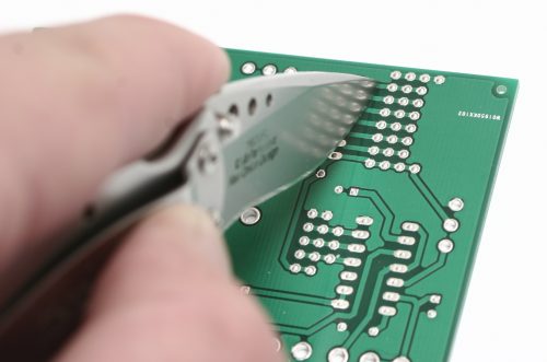
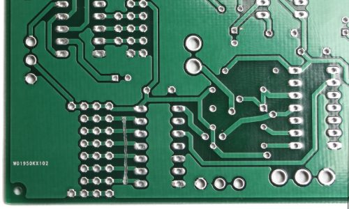
The OG Atari Junk PCB has a few issues that will have to be solved with jumper wires.
First we will need to cut the bad traces. Look closely at the picture above for more information.

Now solder a jumper wire across the points on the trace where the surface has been exposed. Look closely at the picture! This is a very important step. It helps to put a little solder on the exposed areas before setting the wire. Remember to leave room for the other components. The other jumper is a little easier. It jumps the solder terminal inside D1 to the solder terminal labeled C (connect).
On-Board Components

First solder all of the IC sockets to the board.
Make sure the little notch on top off the socket matches the lines on the circuit board.

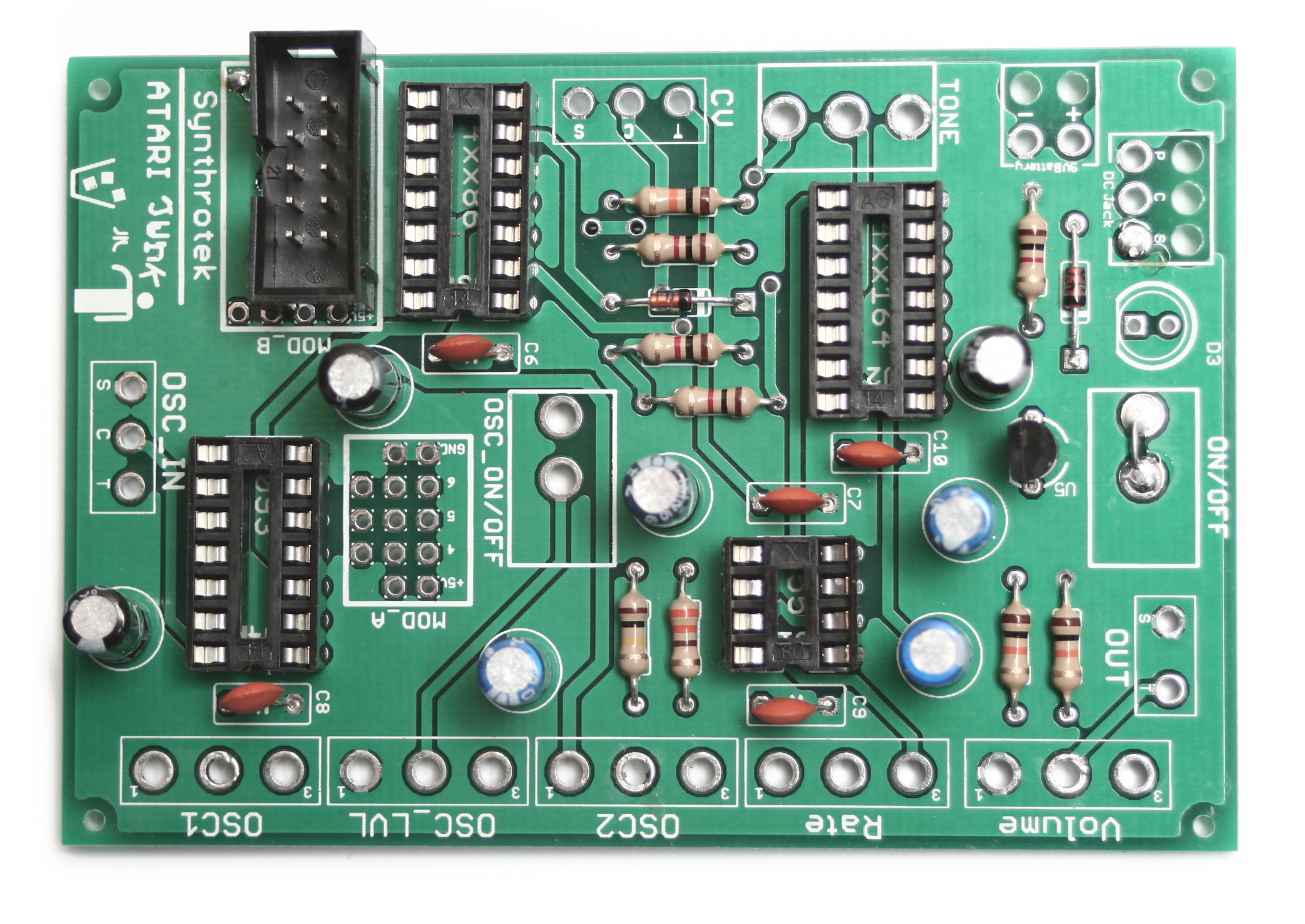
Locate the component identifiers for R1 – R9. Insert the resistors and solder all components onto the PCB.

Our next step will be to add all of the capacitors to our circuit. C6 – C10 identify the placement of the ceramic capacitors.
C1, C2, C3, C5, C11, C12, C13 identify the placement of the electrolytic capacitors.
The longer lead on the electrolytic capacitors is positive. Make sure to match it up with the plus sign on the PCB.

The black band on the schottky diode represents the negative lead.
Match up the black band with the white stripe on the board.
Insert the transistor with the flat side facing the flat white line on the board.
Wired Components
If you want to make this project into a Eurorack project, please follow the Mod Instructions, and not these instructions.
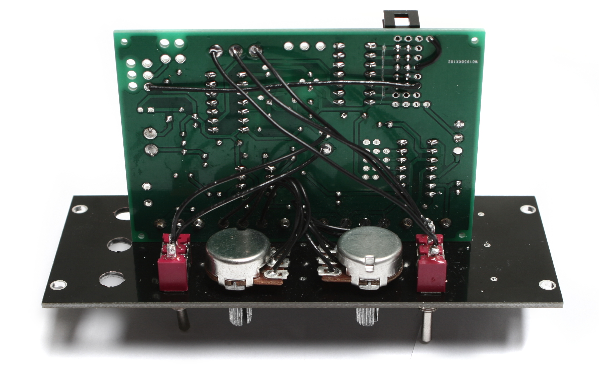
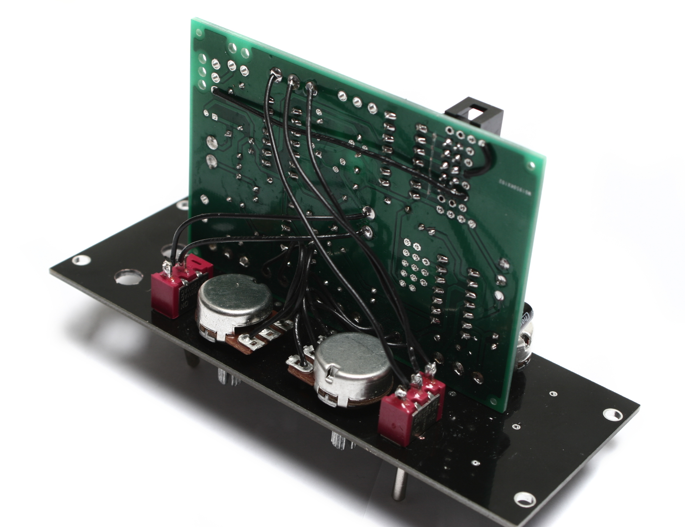
The next major step in our project assembly will be the wired components. Attach wires to all of the potentiometers, switches, and jacks beforehand. This will save time and the construction of the circuit will be much simpler.

When you insert the LED align the flat (negative) side with the flat white line on the board. You can also mount the LED straight to the board, or leave it out entirely (no jumper wire needed).

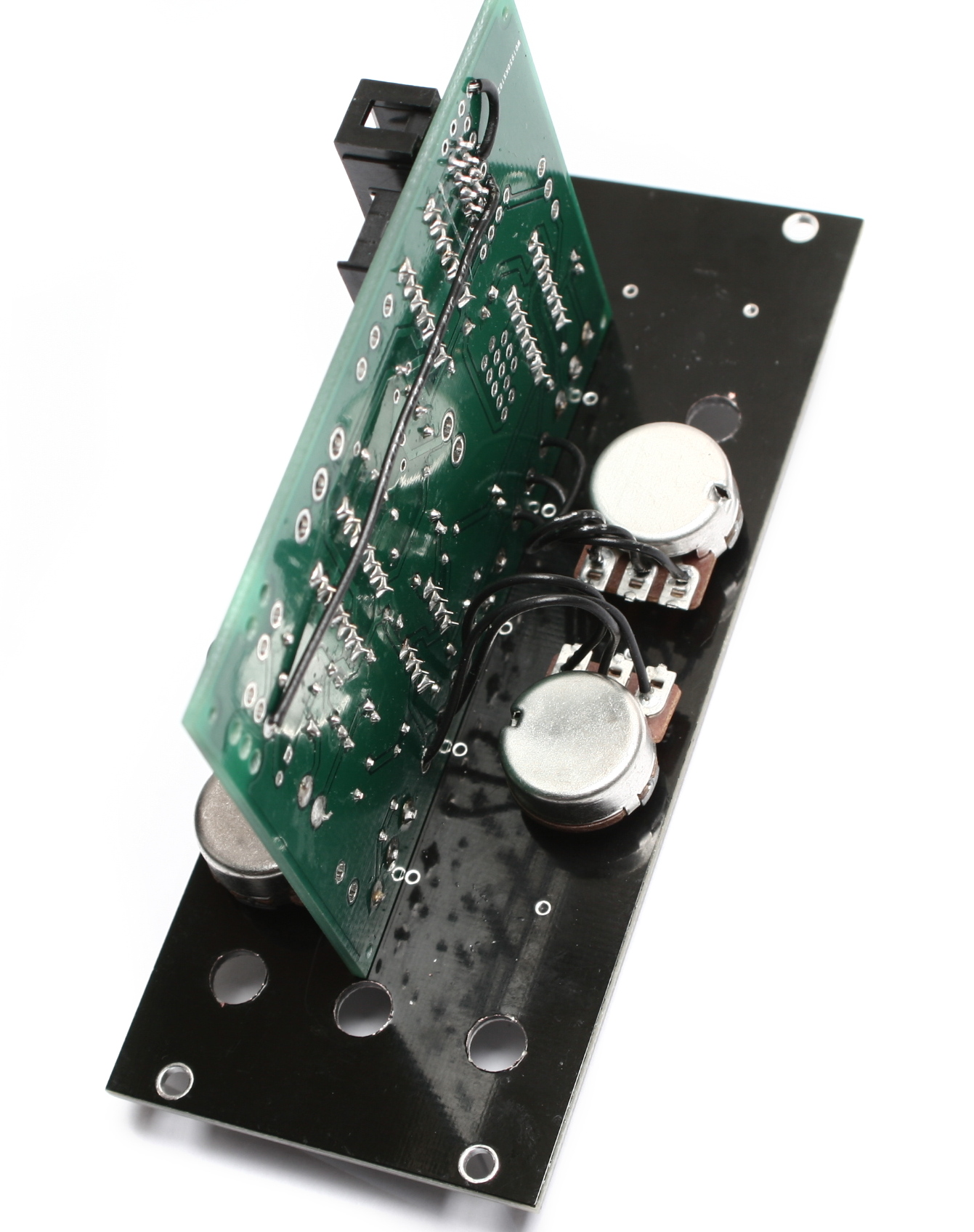
Insert the pots exactly as they are shown in the picture. (Please note: they won’t fit side-by-side if soldered straight to the board.)

When installing the pot, some pots come with nubs near the shaft that may get in the way of installing the circuit into a case. Check for a nub and clip as necessary. Also wire in the audio/cv jacks as shown. PLEASE NOTE: The CV input jack is a switched MONO jack. Your circuit will not function properly if you do not use the proper jack. When a CV source is plugged into this jack, only the volume and rate pots will function, the other 3 will not (this is proper).

Don’t forget to cut the nubs on the potentiometers as necessary.
Now wire up the mono jacks as shown. Take care to wire shunted mono jacks for both OSC_IN and CV_IN – otherwise your circuit will not function properly.
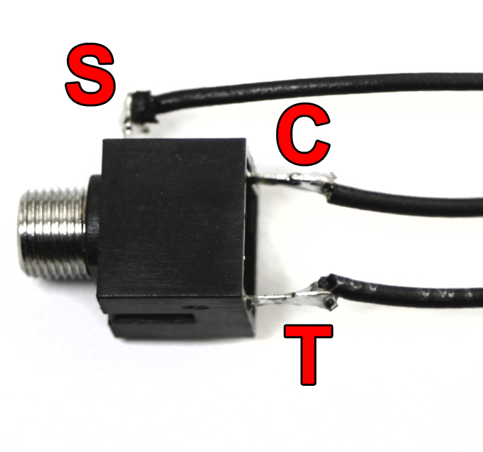

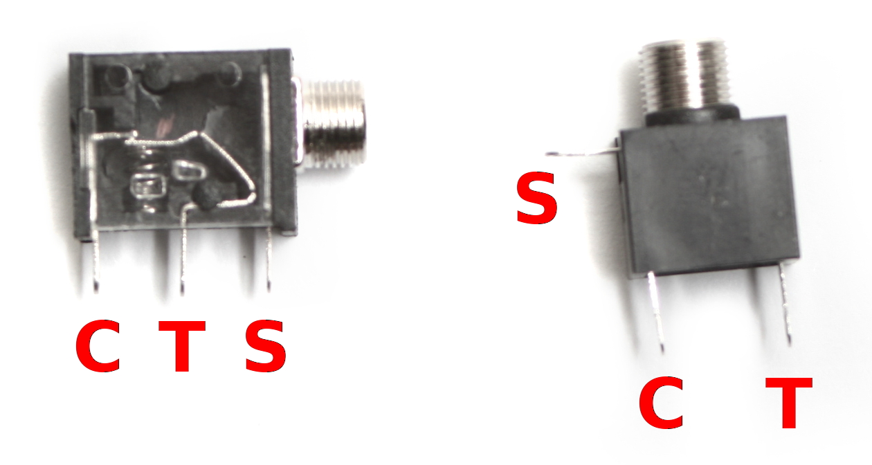
Mono Switched Jack
When wiring the CV Input jack or the OSC_IN jack, follow the diagram above to wire the Tip, Switch, and Sleeve contacts properly to the board. The output jack only uses the T and S contacts.

Wire the switches as shown. There are two SPST switches and one SPDT switch.

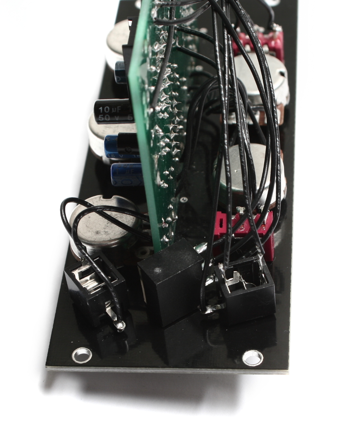
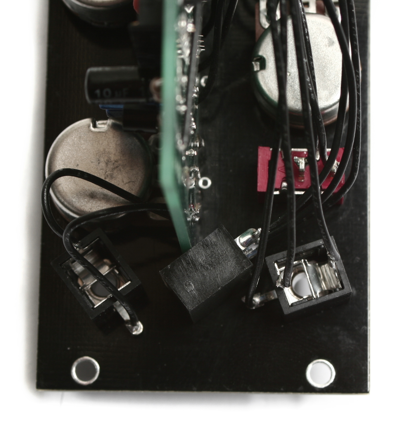
To supply our circuit with power, our next step is to attach the 9V battery jack and the DC jack. The red wire from 9V battery jack goes to the square hole labeled ‘+’ and the black wire goes to the circular hole labeled ‘-‘.
Put the wires through the extra holes before they are soldered to the board. This will add extra stability and relieve tension on the power jacks.
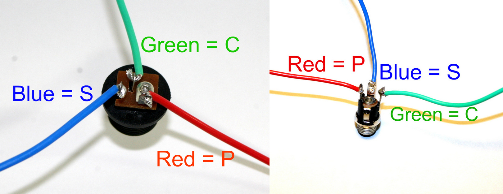
Use this picture to wire up the DC jack in the correct location. P=pin S=Sleeve C=Connect
DC Jack Pinout
If you do not want to install the 9V DC jack and only install the 9V battery clip you will have to short the S and C pins for the 9V DC Jack like shown in the picture below*.
* Your PCB may not look exactly like the photo, that is ok. What is important is that you short the S and C pins together as shown in the photo.
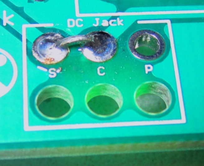
Short these contacts to get the circuit to work without the 9V DC Jack
Almost Done!

Place the IC chips into the circuit. Bend the pins on the chips inward slightly to fit the socket.
Match the half-moon notches on the chips with the notches on the IC sockets.
Congratulations, your Atari Junk Console is complete! Plug in a 9V battery and connect your circuit to an amplifier to see if your circuit is operational. If not, go back through the steps in these instructions and look for any mistakes.
If using a power supply, use a 9V center negative power supply.
Eurorack Mod Instructions
Here are the extra parts needed to make a Euro AstroNoise:
1 x Resistor Clipping
10HP DIY Blank Panel (which will need to be drilled, see diagram below)
5 x Nylon Potentiometer Spacers (optional but recommended)
5 x Black Knobs (optional)
Drilling the Panel
Drill out the panel using the guide below as a reference. You can drill straight into the drill guide holes.
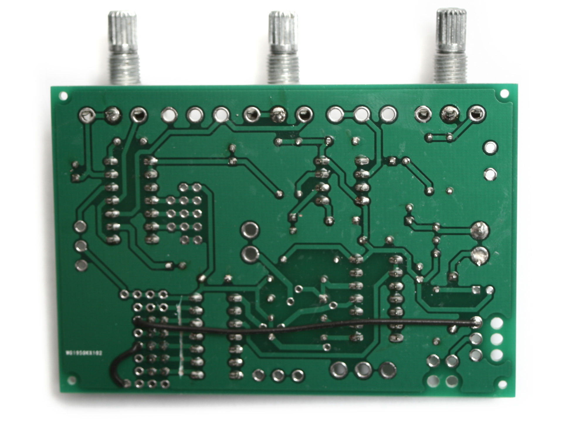
Cutting the Traces
The following instructions are for turning the AstroNoise into a completed eurorack module. If you came here from the very beginning of the page, the first thing that needs to happen is a small cut along a few traces. Please see the image below to see which traces to cut. It is imperative that the very bottom trace in the picture IS NOT CUT. This trace delivers +5v to one of the ICs.
If you’ve already soldered the on board components onto your board, and are ready to mount the AstroNoise to a Eurorack panel, please continue reading for the instructions. Note that we aren’t populating the 9V DC jack, battery clip or LED.
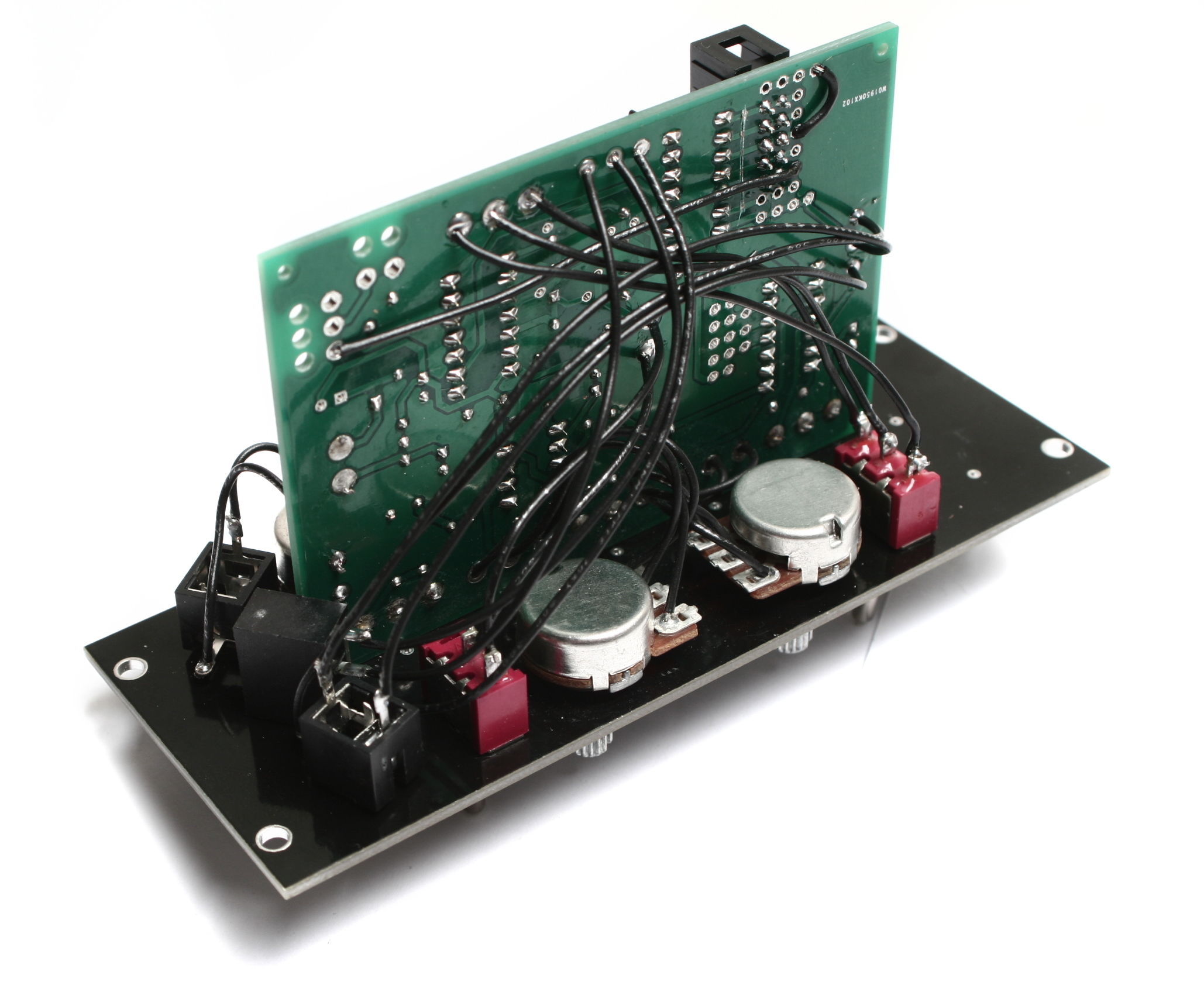
Power Jumpers
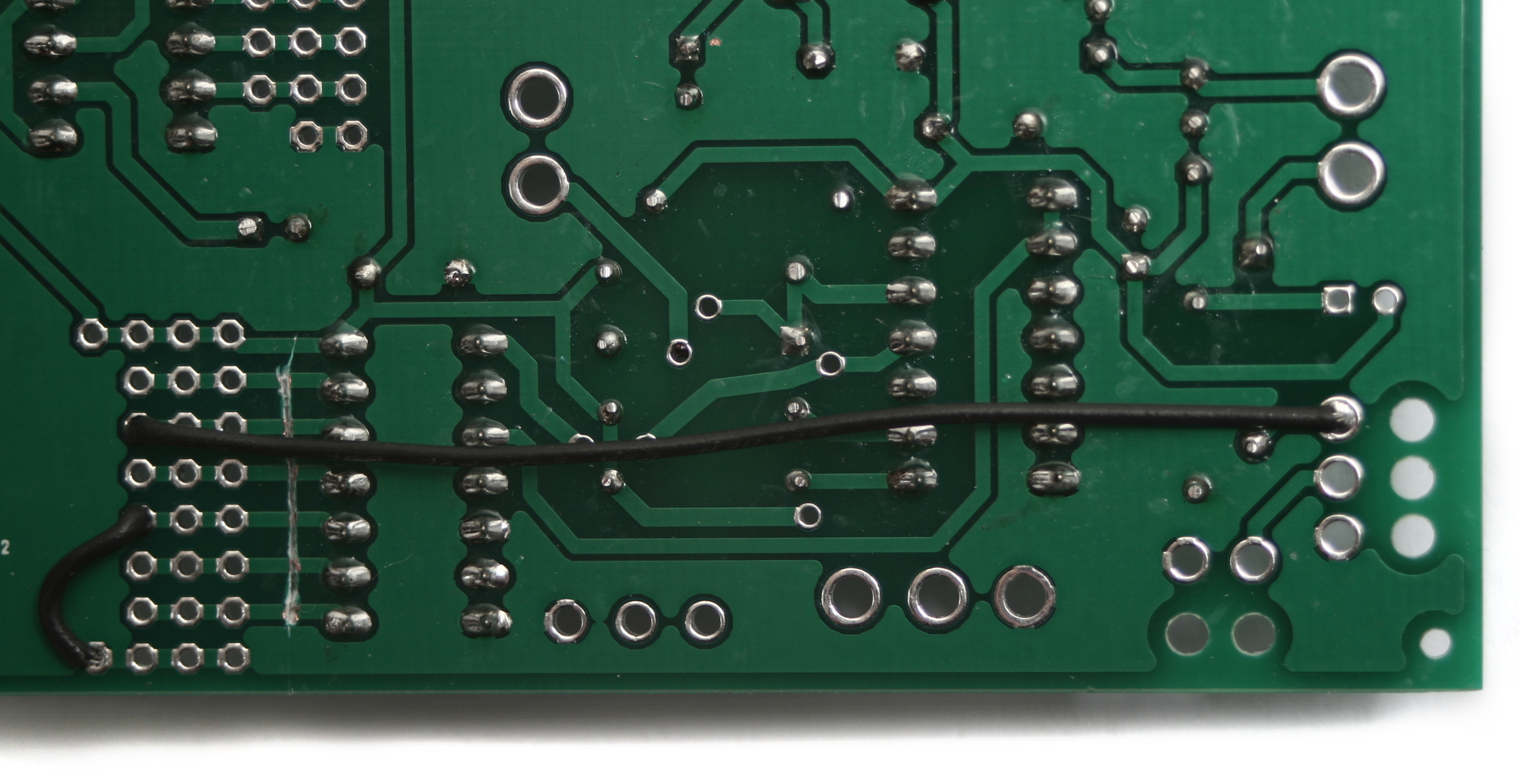 We are going to be soldering the 10 pin shrouded power header in the Mod_B section on the underside of the board. In order to get power from there to the proper spots, we need to run a couple jumper wires.
The first is a short wire that connects the ground. Using the picture above as a reference, solder the wire from the very bottom left hole to the fourth hole up on the left.
The second wire goes from the third hole down from the top on the left, over to the ‘S’ solder pad for the DC jack. Once you have your wires soldered in, clip any excess on the top side of the board, and make sure to cut the ones in the mod section as close to the board as possible. This will help your power header sit nice and flat when you solder it in.
Power Switch Jumper
Next up, we need to take a resistor clipping (or small length of wire) and solder it where the ON/OFF switch goes. This makes it so the astronoise turns on when your eurorack system gets power, instead of having to turn it on with a switch. 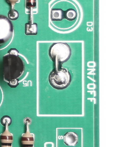
10-Pin Power Header
Next up is the 10-pin shrouded power header. Make sure when inserting this into the board that it looks exactly like the picture above, otherwise your power rails may be misaligned. Insert the header so that the key is pointing towards the edge of the board and the topmost row of pins goes into the row marked ‘8’ on the silkscreen.
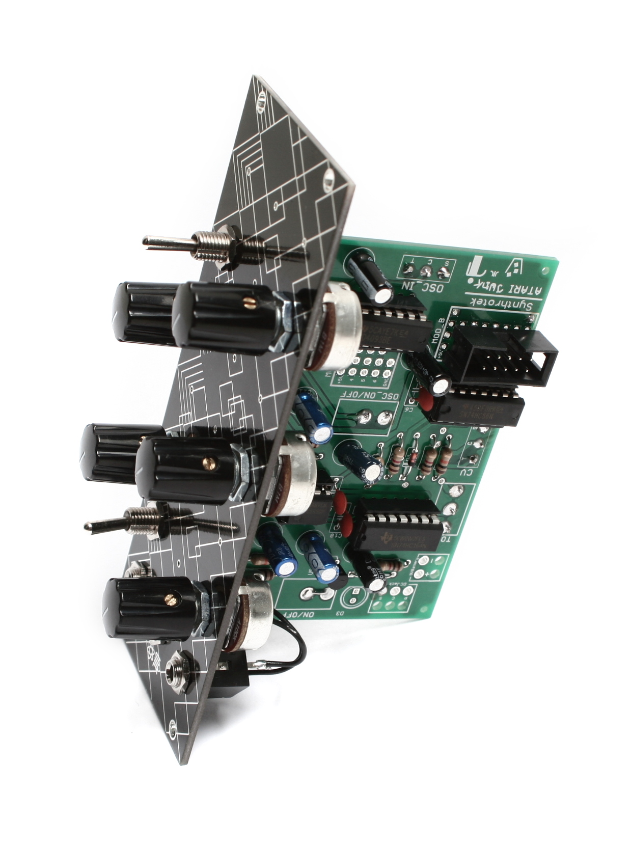
Potentiometers Part 1
This will be step one of two for the potentiometers.
 We are going to start with the potentiometers, but only the ones labeled Volume, OSC2, and OSC1. When you have them populated, carefully flip your project over and solder ONLY the middle pin into place. Then you can go back and make sure everything is seated fully, and straight.
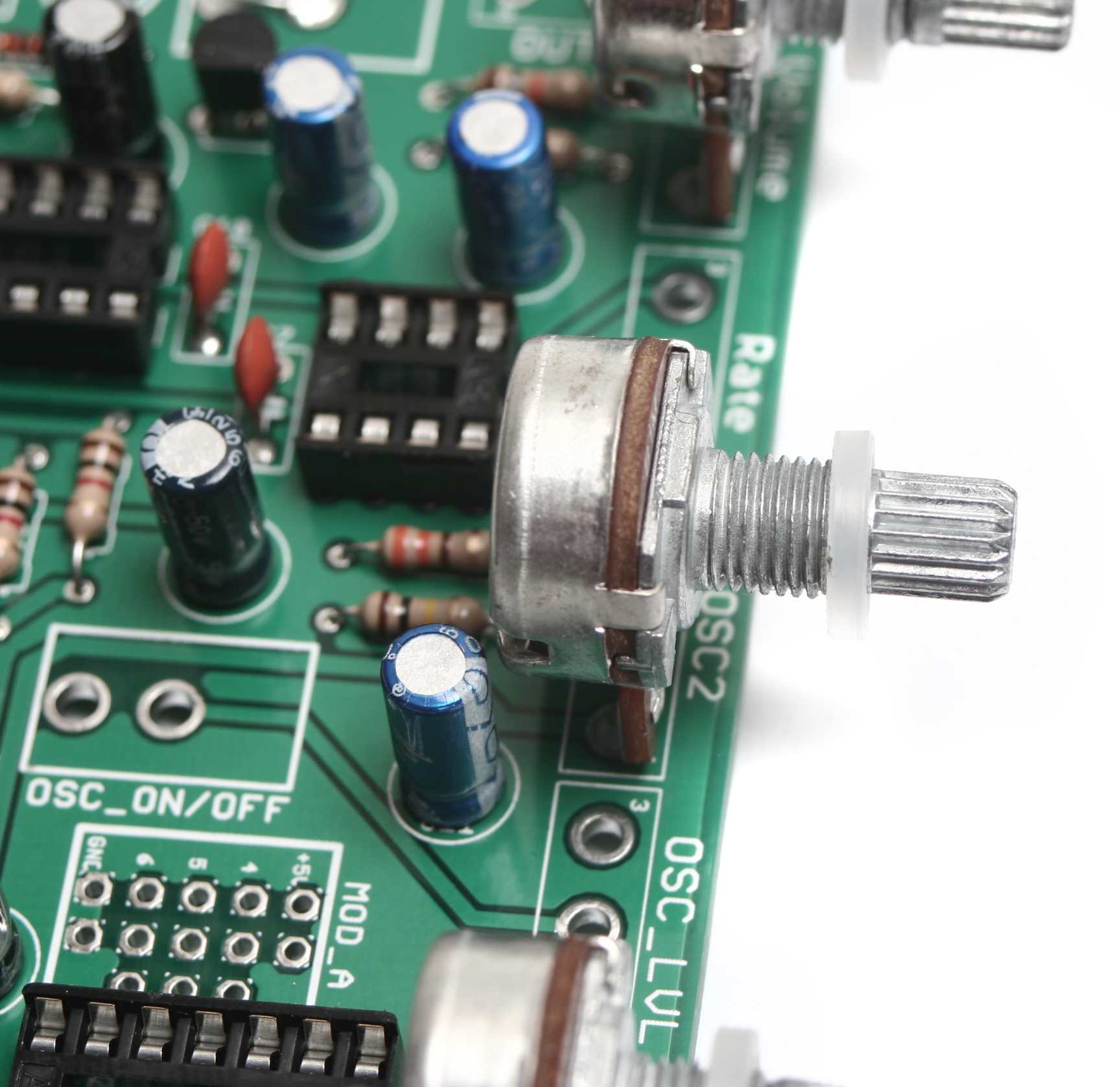 Next, place your nylon spacers over each potentiometer. These will help keep everything straight when you mount it to the board.
Now insert the assembly into the front panel, making sure to get the pots fully seated. Then tighten down the included nuts with a tool. Once everything is mounted and straight, you can solder the remaining pins on the potentiometers.
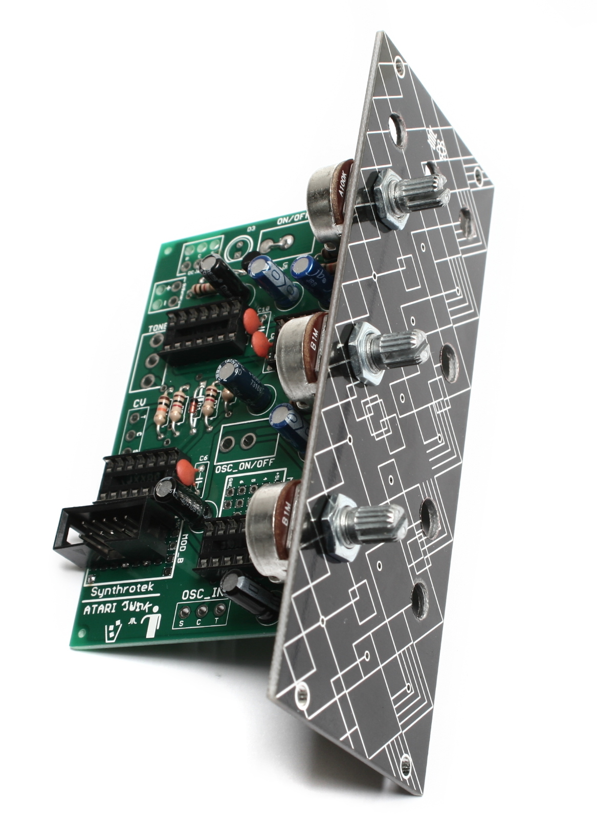
Potentiometers Part 2
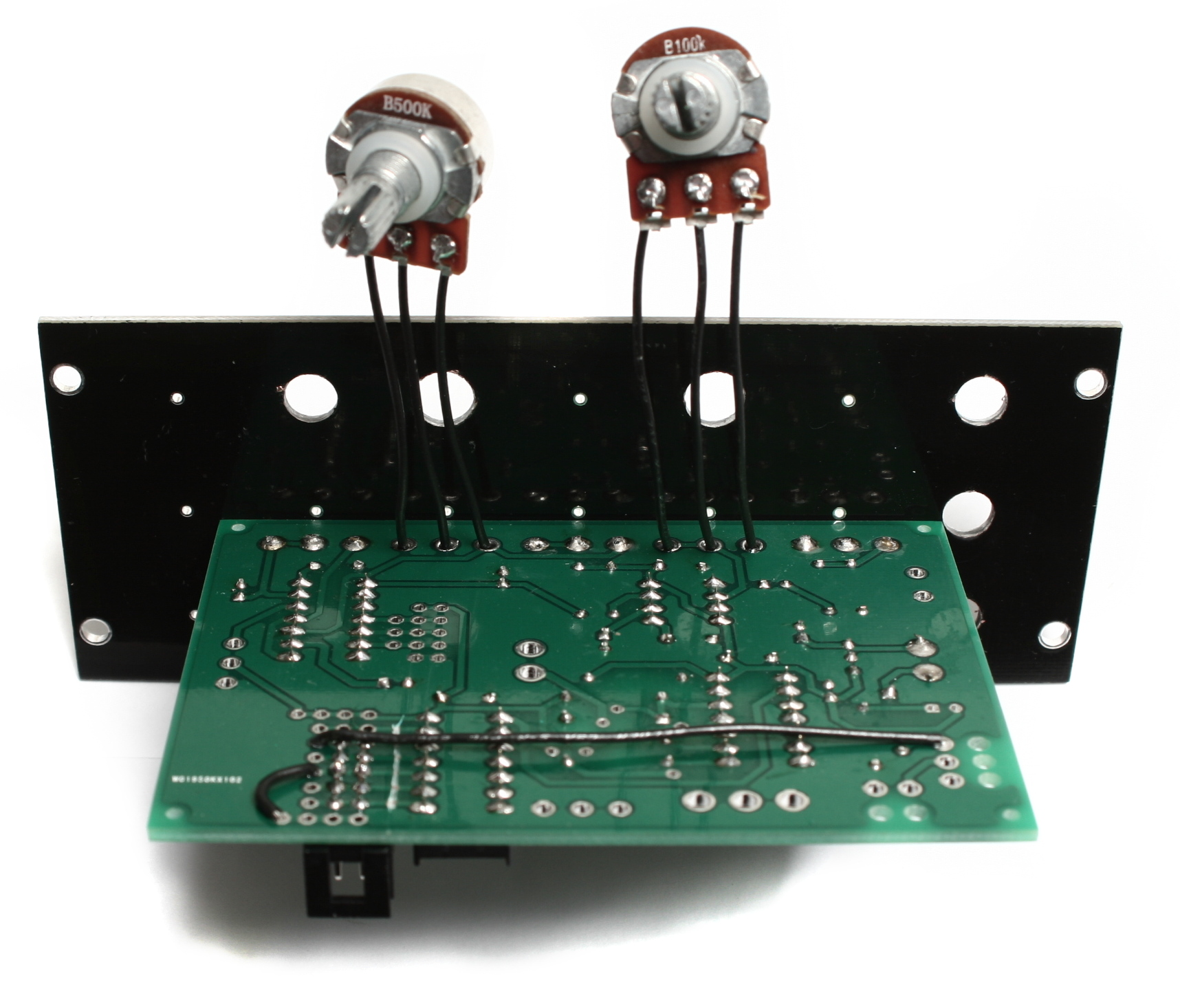
Snip the PCB pins off of the two remaining pots so they look the like picture above. Next, solder short wires to the pots and attach them to the board as shown above. They should be soldered into the Rate and OSC_LVL spots.
Next, slide the nylon spacers onto the potentiometer shafts, then mount them as shown, with the leg side of the bodies pointing towards each other. Tighten them down and double check one last time that they are straight.
Switches
Next up are the switches. There are two, an SPDT center off and an SPST switch. The SPST switch only has two legs, while the SPDT center off switch has three.
Mount the SPST switch in hole just below the potentiometers you mounted in the last step and wire it up to the OSC_ON/OFF position on the underside of the board. The orientation on the board doesn’t matter, just solder one wire into each hole.
The SPDT center off switch goes in the hole above the potentiometers and is wired to the board inside the TONE box on the underside of the board. As long as the middle wire from the switch goes to the middle solder pad in the TONE box, it doesn’t matter which spots the other two get soldered to.
Jacks
Now we can prep the jacks. There are three jacks: one of them is right-angle, the other two are the normal solder lug style. The hole spacing on the panel is really close to the board, so the jacks must be installed in a specific way in order to not hit the rail or each other.
Start by cutting wires for each jack to an appropriate length, leaving yourself a little extra just in case you made it to short. Solder these wires to the legs of the jacks (except the ‘C’ leg of one of the solder lug jacks – this leg can be clipped off if desired).
The picture above, from left to right, shows the output jack (OUT on the PCB; wire the S and T leads only), CV in jack (CV), and then oscillator input jack (OSC_IN). Once the wires are soldered to the jacks, mount the jacks to the panel, then solder them to their corresponding places on the board.
Here’s a close up of the jack orientation.
Once everything is soldered in place and looks just like the picture above, just clip all your excess wire.
Completed Unit
Congratulations! You just finished the Eurorack mod for the AstroNoise! If you are having trouble getting it to fit inside your rails, double-check that you have the jacks oriented properly, as if they aren’t turned enough, they can interfere.
What’s up on a schematic? I would like to build this, but not from a kit! For me it is more fun to construct my own circuit board layout from scratch. If you could post a schem. along with parts that would be dope! I’m sure I have them sitting in my garage.
Has the pcb issues been fixed for new ones being shipped out? If not, is there a plan to?
@andrew
There are issues? man I just got mine today! If I had known that I woudn’t have bought it? Is this true synthrotek? What happens if I solder it all together and it doesn’t work I can’t send it back with all my stuff soldered to it? This can’t be true. I had not problem with the Atari Punk board I got from you guys.
@marc and @andrew, yes the board was manufactured with 2 overlapping traces. The above instructions do not hide that fact and show how to correct the issue. Once current stock is depleted the new version will not require this modification.
Schematics for all our kits
HI Marc, can you get us some photos? the circuit does work, I would need to see if there was an error in soldering, etc. Thanks, lets make this thing work!
Thanks you for the schematics I can’t wait to build one!
Hey Synthrotek!
I recently emailed you about an Atari Junk that I was building with missing pieces. Got it today! Thanks for the speedy turn around!
As luck always has it, I installed the switches and and still having trouble getting it to generate sound/turn on the indicator light. I accidentally requested to have all the circuits installed when I ordered it, so I assumed all the components were in right. I just realized that there isn’t a jumper wire in the first set of bad traces near the big area of capacitors. I’m assuming this is something that needs to get fixed? I dont want to try to take out/fuck up the capacitors before I’m absolutely sure i’ll need to!
– Seth!
Thanks for the patience Seth! I can look into which version that you received, but our new Atari Junk PCB’s do not need any traces cut, etc. Did you install the DC jack?
Could you clarify this: “Extra jumpers will have to be placed in Mod_A and Mod_B for your circuit to work.”
I just need to know if that is part of the general instructions or in the case that I don’t want to use the DC Jack.
thanks!
Changed this on the instructions, they are not necessary. thanks!
Is there a chance that one might receive one of the older panels that might need to be jumper’d even though I purchased it just a week or so back? I’ve hooked up everything so carefully, and double checked everything. I’ve hooked up both the DC and the battery. I’m getting no sound at all..just a bit of light response from my amplifier. How do I clearly identify one of the older boards? Frankly, from appearances, mine looks like one of the old ones that needed the mod.
Thanks.
Ron
Hey Ron,
Unfortunately we ran out of those old boards a long time ago, and we don’t keep a large backstock of kits. However, if you can take a good picture of the pcb, around the area where r4-r7 are, thats the easiest way to determine old vs new. The old one has a trace that goes from c7 to the T terminal of the power jack, and has an intersection that also connects that trace to d1(cathode) and pin 2 of U3. The new one separates these two traces. If you can’t get it working, feel free to send it in to us, we can give it a free 30 minute examination for you, to see if we can spot something.
Very kind. Thank you. Having some bad luck with builds lately; sometimes that happens to me. I need to stick to working on my modular. Before I start carving on it, maybe I’ll send it your way to see if you can spot the obvious that I’m probably not seeing (“Hey knucklehead…you put the diode in backwards!”). Anyhow, thanks again. I’m going to study it a few more times first.
I am not understanding the C for the mono jacks. I am using 1/4 jacks as I do for all my builds. Mono jacks only have 2 points to solder to. So where does the C go and what does C even stand for? If I use a stereo Jack where would I solder the c point to? And can I even omit those 2 jacks if I wanted to? Would the circuit still work? Thanks
Hi Matt, the CV input jack is a switched mono jack. “C” is for the switched part of the jack.
This circuit needs a switched mono jack to function properly
Hey,
My PCB arrived Yesterday, all components were compiled during the wait to receive it.
I have built it and there seems to be a problem.
It just makes a dull clicking sound and not the scape of sound in the video.
After checking the build sequence and checking all soldered connections I’m still coming up with nothing….
The over lapped trace issue doesn’t seem to be a problem with my board, so it’s not that.
Any ideas??? I’m eager to make sonic mayhem and the NAND synth just does’nt do it for me any more.
Cheers.
Hi Phil, hard to tell without more info. Check out our troubleshooting guide:
http://www.synthrotek.com/tech/troubleshooting-your-build/
If this does not help, send us an email with photos and we will try to help further.
A very useful guide Steve, thanks…turned out to be an incorrect cap value.
My next issue is the OSC_LVL, OSC1 and OSC2 knobs do nothing with the OSC ON/OFF in the ON position. The obvious have already been checked, I’me going down the replace IC route…any ideas?
Dah….Cheap chinese parts strikes again. CV sockets not switching back when the jack is removed. That will learn me.
Thanks again Steve for your help so far, my ne PCB will soon arrive…yay. Echo cho cho cho…
@Phil Tobin
Hello, I have the same problem …… could you repair it? How come?
Thank You
The kit I received has 1/4 in mono jacks. Not switched jacks. Can I complete this with what was provided or do I need to source the switched jacks on my own?
We goofed Sean, those will not work. We changed the BOMs to reflect the change needed. I will send you out the correct jacks today. Super sorry for the hassle
Hi just a quick question. Have built the complete unit but osc1 osc 2 and osc level and osc on/off do nothing. I’ve only just bought this pcb recently so I assume I don’t need to bother with the jumper wires etc although the board does have extra holes near D1 and the resistor next to it. Any ideas? Cheers, Paul
One thing is that I haven’t fitted the osc in jack or the cv jack. Didn’t think that would matter but now I’m not sure.
Thanks for sending those replacement jacks so fast. I replaced them today and the Atari Junk works great. Sending a sequenced Chaos Nand into the Osc-in on the AJC sounds ridiculous!!
Hey,
Thanks for the awesome diy products!
I do have one rather strange thing happening though.
The ajc doesnt seem to function properly when I swtich it on, until I change the volume and tone switch once… After that it works just fine… Is that normal behaviour?
Cheers!
Hey Ewoud,
Yeah, unfortunately with this circuit, sometimes the oscillator can get stuck, and won’t function properly until a couple of the pots are changed.
Hey well done Ewoud!! You posted your question two weeks after I did and got an answer the same day!!! Still waiting for a reply to mine. Nice,good for you mate.
@Paul Blackburn
Hey paul, sorry I missed your first question, thats totally my bad! You definitely need those jacks in there, the circuit passes signal through the jack, and when you plug another source in, it interrupts the signal.
Hey Patrick thanks for your reply! Sorry for the sarcasm,was getting a bit desperate and am really anxious to get this up and running,also it’s the first time I’ve built this synth which makes trouble shooting harder for me,once I’ve built one successfully I’m pretty good with fault finding. That’s really good news although I forgot to get the switched jacks on my parts order so will have to pay over the odds for them locally. Thanks again,have a great day!
Hi there, hoping you can help me out. My AJC is sort of working, but not fully, or properly. The only wat I can get any sound is if I run a jumper connecting caps c3 and c5, and even then, the unit basically works like a punk console. The pot for osc 1 doesn’t do anything. Am I correct in assuming that resistors can be put in in either direction? Besides that, I cannot find anything different between the pictures in the instructions and what I’ve done. I coud send pictures if needed. Thanks.
Hey Troy,
If you haven’t, I would recommend taking a look at our troubleshooting guide here. If your jumper is running along a trace, there’s a good chance that the trace that runs between them is broken. You are correct that resistors can be placed in either direction, they are non-polar.
The oscillator not functioning could be a couple issues, like something amiss with the osc on/off switch. Another common problem is jack type. The CV in and OSC in jacks NEED to be switched mono jacks, because the signal passes through the switch when nothing is plugged in. If there’s a non-switched jack in there, then no signal will be able to go through. If you have further issues, you can always contact us at synthroteksales@gmail.com
Are there any published mods for this circuit?
Thanks!
Hey there,
There are not currently any mods for the Atari Junk, but if you figure some out, feel free to post them and share!
Best,
-Patrick at Synthrotek
@Patrick Kelly
I really wish I had known this earlier, would have saved me a lot of frustration. It really should say in the assembly instructions that this is expected behavior!
Other than that I have no complaints. The AJC is my favorite noise synth!
P-A,
The AJC is definitely my favorite noise synth by a long shot too, nothing else can come close to that crunchy goodness.
Best,
-Patrick at Synthrotek
Hi. Have an AJC that makes no sound and the tone switch seems to kill the circuit. Any ideas?
Hey Michael,
It sounds like the could be something shorting that switch to ground. However, it could be a number of things. I would suggest emailing us at store@synthrotek.com with pictures and videos of your AJC.
Thanks
-Zach
Just started working on the AJC today.
I’m curious what Mod A and Mod B are on the circuit board.
Are they for future use?
Are they designed for connectors?
This is so cool. My seven-year-old and I are having a blast.
Hey Pj,
Mod A and Mod B give you access to unused pins on their respective ICs.
You can use them to wire in separate circuit boards or solder in different components to make it self oscillator to do cool stuff.
My best suggestion is to look up the datasheet for those ICs and see if there are any mods you can build up.
Good luck
-Zach
So I’ve been studying this for a while.
Osc1 and Osc2 use 2 of the 4 gated oscillators from the 4093.
Mod A gives you a space to add a Resistor/Capacitor network to create an additional oscillator from the 4093. The resistor could be fixed, a pot, a photoresistor, or ?
My question is, how would you route the output of a 3rd oscillator to the speaker output (where to plug the jumpers?)?
Also, what exactly is a CV input, and what are some real world examples? I see that using the CV jack disconnects the 4093 oscillators.
Also, the Osc_Input, realworld examples?
Thanks for your help.
thanks
Okay, CV stands for control voltage. I built a Velleman variable power supply a long while ago and never used it, so I suppose I will get it together with a new plug.
I would still appreciate an answer to my other questions.
@PJ Holcombe
-You can also use a vactrol to convert voltage to resistance. It’s a quick way to gain CV control over the oscillator.
-I suppose you can connect the output anywhere in the circuit. Some spots may be more fun/effective than other mods. But I imagine the most straight forward way would be to jumper it in after R2 or right before the volume control pot near the output.
-Real world application of the Osc_Input would be to mangle the sound of separate oscillator.
Hi guys, I’m about to get started building the A J C. I’m planning on building it in a die cast Hammond case along with one of your optical theremin kits. How should I wire up the 9v power socket,? Centre + or centre –
Thanks
Hi There,
I am about to build my kit, but am thinking of building it as Eurorack rather than standalone. That being said, is there a plan to release a proper ‘silkscreened’ Eurorack faceplate for this kit? That would look much nicer than the generic (and thus unlabeled) option described here.
Hi Olaf, we have wanted to get this into Eurorack production for a long time, but nothing yet. It will be a much different design when we do make it. I would suggest making your own for now.
Hello everybody ! Does the AC adapter should be centered negative polarity for this one ? Thanks for your answer !
Hi Clement, It matters on how you wire up the jack, but if you follow our instructions it will be 9V center negative
How do you wire the DevDelay circuit into the AstroNoise circuit? Do they share a power supply? So you just need to wire a jumper from the AstroNoise positive to the DevDelay positive along with the ground? Where does the audio signal need to be attached?
The two circuits can share a DC jack, they both accept a 9V center negative power supply. You can wire the power as you described, that will work fine.
To join the circuits, wire the output of the AstroNoise directly to the input of the PT2399 Dev Delay.