


Important Links
Product Page
Store Page
Assembly Instructions
Bill of Materials
Quick Start Guide
Capacitor and Resistor Lookup Guide
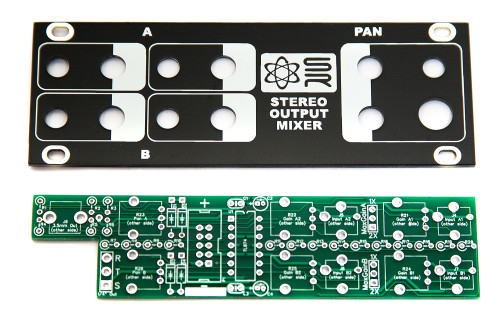
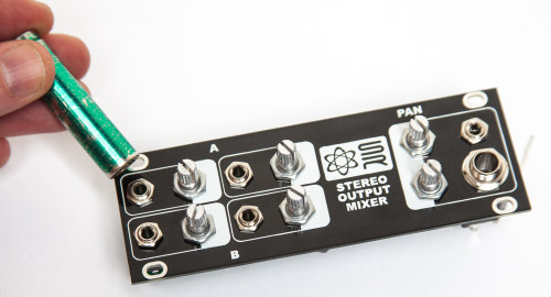
Synthrotek 1U Stereo Output Mixer PCB/PANEL
Thank you for purchasing the Synthrotek Eurorack 1U Stereo Output Module kit! This is an intermediate build as it has many stand-up resistors and tight soldering. If you feel like you can handle it please proceed! If not, get some help from a friend with experience or purchase a fully completed unit.
ATTN: Please follow the BOM and these instructions and don’t populate from the PCB alone. Also sometimes we cannot get the exact pictured components, so please look over your parts and check the codes first. Lets begin!
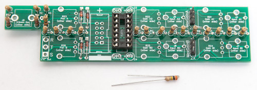
DIODES
Start with the diodes as shown below, then turn over on a firm surface to solder, then clip your leads. Diodes are polarized components so you must match the black stripe on your diodes with the white stripe on the PCB silkscreen.
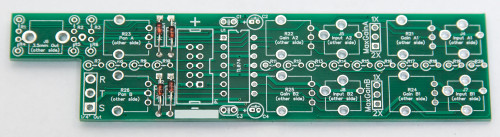
1U Stereo Mixer Diodes
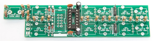
IC SOCKET
Place the IC Socket by aligning the notch with the notch graphic on the PCB Silk Screen. Turn over on a flat surface and solder into place.
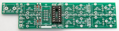
1U Stereo Mixer IC Socket
JUMPER HEADERS
Placing the jumper header pins can happen now OR after you solder the resistors in place. It depends on your technique, but we like to add them at this point. Place the 3 PIN Jumper Header Pins in place. Turn over on a flat surface and solder into place.
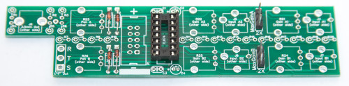
1U Stereo Mixer Jumper Headers
RESISTORS
There are quite a few resistors that need to be installed standing up. It is helpful to bend over one of the resistor leads first before populating each resistor. Solder and clip leads.
1U Stereo Mixer Resistors
CAPACITORS
Add the non-polarized capacitors as shown below. Next, make sure you orient the electrolytic capacitors in correctly. The longer lead needs to be inserted into the hole that has the “+” marking near it. Turn over to solder and clip leads.
1U Stereo Mixer Capacitors
10-PIN POWER HEADER & IC
Next add the 10-Pin Eurorack Power Connector in place by matching the key notch with the key indicator on the PCB silk screen. Turn over and solder on a flat surface. Then add the IC by aligning the notch of the IC with the notch on the header and pcb silkscreen.
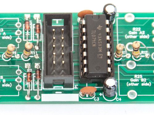
1U Stereo Mixer Power Header & IC
JACKS AND POTS
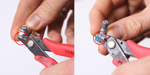
Don’t forget to cut the nubs on the potentiometers as necessary.
Now place the jacks and the pots on the other side of the pcb as shown below (do not solder just yet!).
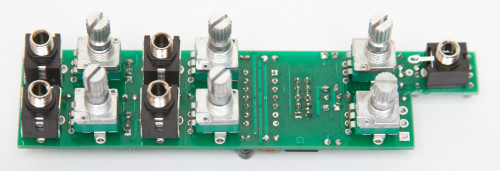
1U Stereo Mixer Jacks and Pots
1/4″ STEREO JACK WIRING
WARNING: If you didn’t purchase your 1/4″ Stereo Jack from us, beware that the pinout may be different from what we show below. Read your datasheet carefully and make sure you wire the proper pins to the T,R, and S solder pads.
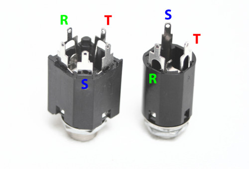
Stereo Jack Wiring
Now cut and strip 3 pieces of wire, and solder to the points as shown below:
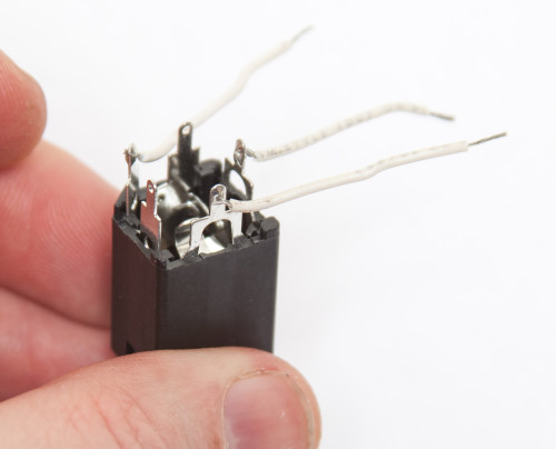
1U Stereo Mixer 1/4″ Jack Wiring
Take the 1/4″ Stereo Jack and secure it onto the backside of the panel as shown below:
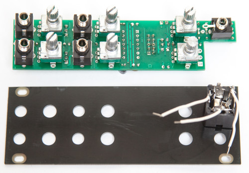
1U Stereo Jack Wiring and Panel Placement
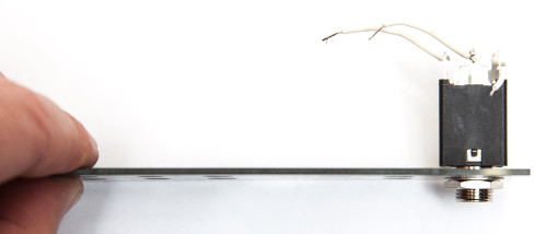
1U Stereo Mixer 1/4″ Stereo Jack Panel Placement
PANEL PLACEMENT
Now marry the PCB and the Panel and fully tighten (not too tight) the jack nuts and pot nuts as shown below:
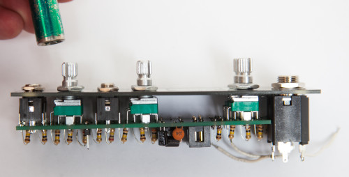
1U Stereo Mixer Panel Placement
1U Stereo Mixer Panel Placement Nuts
Make sure that the panel and the PCB are parallel to each other and not at an angle. This will take a bit of shifting and pulling (very gently!) on the PCB to keep the distance the same across the module. Take it slow!
1U Stereo Mixer Panel Straightening
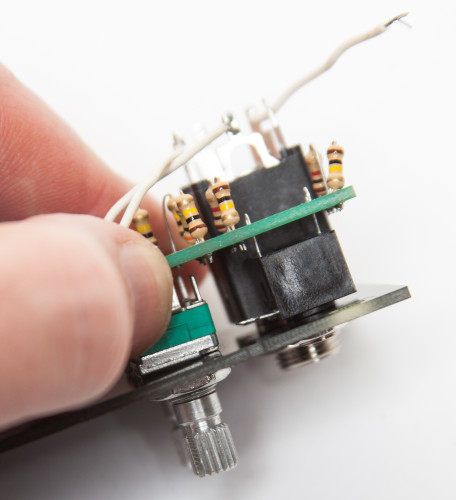
After you are done aligning the panel to the PCB you can now solder the jacks and pots in place. You now need to solder in place a resistor lead clipping to the the 3.5mm stereo jack as shown below:
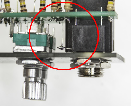
1U Stereo Mixer 3.5mm Stereo Jack Pin Wiring
WIRING THE 1/4″ STEREO JACK WIRING
Finally, take the 3 wires coming off the DC jack and solder them to the PCB as shown below. If you get confused as to which leads connect to the PCB, please see the graphic detailing the pins in the instructions above.
WARNING: If you didn’t purchase your 1/4″ Stereo Jack from us, beware that the pinout may be different from what we show below. Read your datasheet carefully and make sure you wire the proper pins to the T,R, and S solder pads.
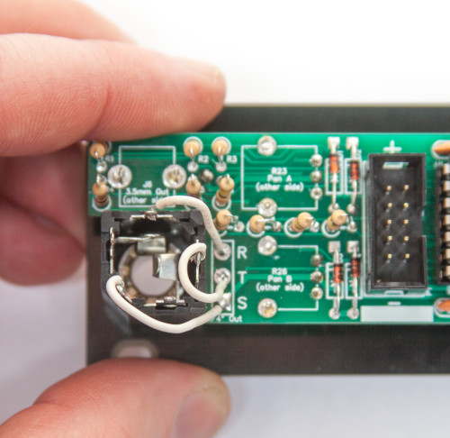
1U Stereo Mixer 1/4″ Stereo Jack Wiring
Now you can add the jumpers to the Max Gain Header Pins as shown below. Choose 1x or 2x gain per channel. You are now done and ready to test your module. If you module is up to par, you are free to add your knobs. Enjoy! If you have any questions or need help debugging, please first refer to our troubleshooting guide BY CLICKING HERE. If this gets you nowhere, please contact us by email for support. Thank you again for purchasing your kit from Synthrotek!
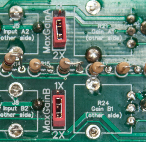
1U Stereo Mixer Jumpers