


Important Links
Product Page
Store Page
Quick Start Guide
Assembly Instructions
Bill of Materials
Schematic
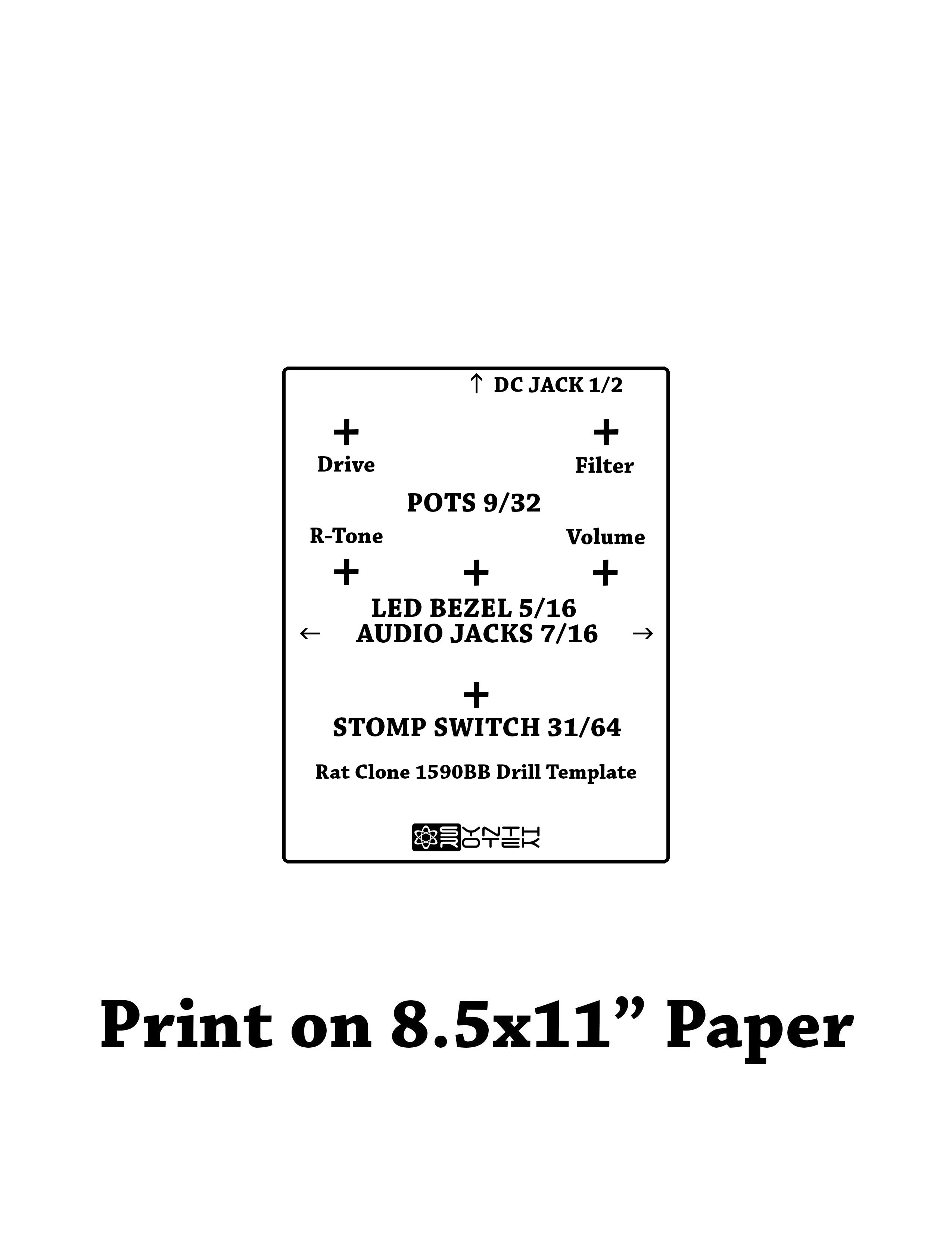
Drill Template Capacitor and Resistor Lookup Guide
RATATAK LM 308 Distortion Pedal Kit WIRED Assembly Instructions
Wired Rat Visual BOM
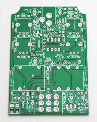
LM 308 Rat Clone PCB
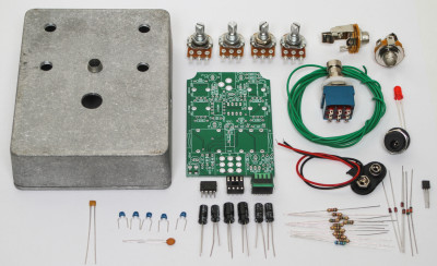
Thank you for purchasing our new Wired Rat Clone Kit. If you are looking to build this kit into a compact 1590B sized metal project box, please consult our PCB Mount version of this kit. Please follow these instructions in order, as it can be tricky to build and insert into the enclosure. ALWAYS REFER TO THE BOM FOR THE MOST RECENT AND BEST COMPONENTS. DO NOT RELY ON THE PHOTOS ALONE!
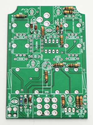
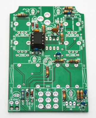
RESISTORS & DIODES
Rat Clone Resistors and Diodes
Please consult the BOM prior to adding any component. While we try to keep the same looking components in stock, variations of appearance will happen. Do not rely on the photos alone. If you need help reading components, check out our resistor and capacitor code charts in the menu at the top of the page. Add all of the Resistors and diodes, solder and carefully trim your leads. D5 and D6 are the germanium diodes. PLEASE NOTE, RX2 is not populated in the above photo, but there needs to be a 100 ohm resistor in this place.
IC Socket, IC and Ceramic Capacitors
Rat Clone IC and Socket
Now add the IC socket by matching the notch in the socket with the notch on the PCB silk screen and then place the IC in the socket carefully and again align it with the notch.
Electrolytic Capacitors and Transistor
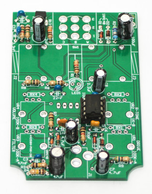
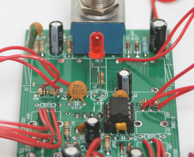
Wired Rat Clone Capacitors and Transistor
Electrolytic Capacitors and Transistors are polarized and thus can only be placed into the PCB one way. Insert the longer lead of the capacitors into the hole that has a “+” next to it. Align the transistor with the silk screen on the PCB by matching the flat edges. Solder and clip leads.
Clipping Diodes Selection Piano Switch
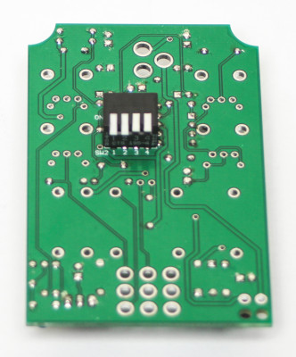
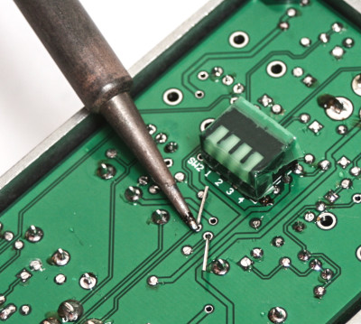
Wired Rat Clipping Diode Piano Switch
Place the piano switch as shown above. The switch will allow for symmetrical and asymmetrical clipping diode selection. Pressing down 1 and 2 of the piano switches set up the pedal for symmetrical silicone diode clipping and 3 and 4 set up the pedal for symmetrical germanium diode clipping. Mess around with these to your liking to achieve your desired tone after you pedal is complete.
Wiring Potentiometers and Jacks
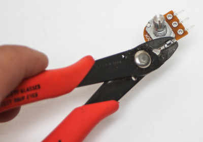
Trim Potentiometer Notch
First trim the metal alignment notch on the pots as shown above. Failure to do so will result in a canted mount.
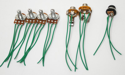
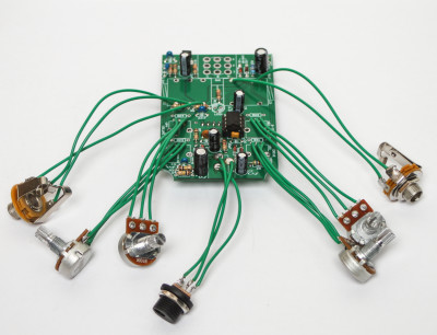
Jacks, Pots and DC Jack Wiring
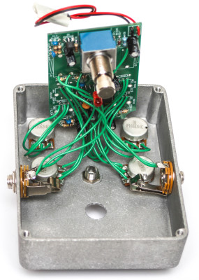
Next, trim the desired amount of wire, trim both ends and then wire as shown above. If you have purchased our pre-drilled enclosure, the lengths above are more than sufficient.
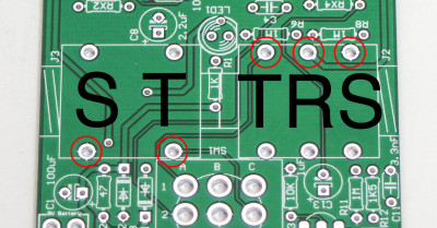
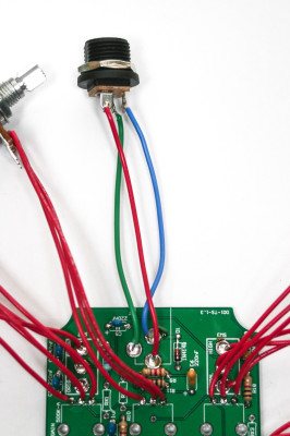
WIRED RAT AUDIO JACK WIRING
Connect the wires for the audio jacks into the red holes corresponding to the picture above and below.
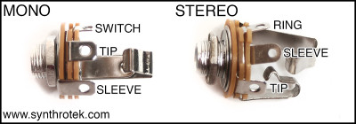
1/4″ Metal Audio Jack Wiring
Next, wire the DC jack as shown below. The colored wire is for reference only.
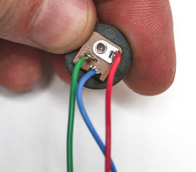
wiring the dc jack
wiring dc jack to pcb
Wire the potentiometers as shown below in order for the pots to turn the correct way.
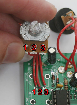
Potentiometer Wiring Order
Wired Rat with Wires
3PDT Stomp Switch
Now add the stomp switch as shown below and solder in. If the fit is tight, just press it through with some effort.
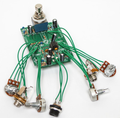
Wired Rat 3PDT Stomp Switch
LED PLACEMENT
There are 2 ways that you can solder in your LED. You can either populate the LED loosely by placing the project into the enclosure and through the LED bezel and then pushing the the LED tight then soldering down (photos 1 and 2). Or you can wire it it up with the provided wire and use the plastic LED crimp (photo 3). At any rate, make sure you align the flat side of the 5mm LED with the flat side on the PCB silk screen graphic.
Wired Rat LED #1
Soldering LED #2
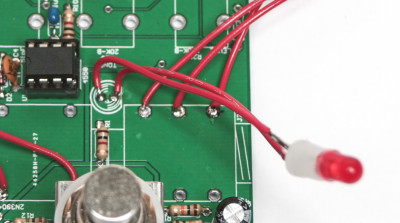
Wired LED #3
Finally solder in the 9V battery snap and place the pots, and jacks in first and gently tighten. Then align the LED and stomp switch into their respective case holes and press through and tighten down nuts. Now is a good time to test your circuit BEFORE placing it into the enclosure.
Placing the project into enclosure
Once your project has been all tightened down, you can place the enclose back plate on and screw down. Feel free to get crazy with some paint or DIY graphics and rock out! Having troubles with your circuit? CLICK HERE
I would like to exclude the Filter pot from the circuit. How would I wire up the circuit? I have read elsewhere that you can short 1 and the wiper (2) and place a resistor of the same value as the pot between 3 & the wiper if you are leaving a pot on the board but how should it be wired if you don’t want the pot in there at all?
Hi John, dont populate a resistor or pot and use some test leads to try pins 1 and 2 or 2 and 3 to see which way works.
How do I wire up for external diode switches?
You can use a SPST switch per row of diodes. Just add two wires and and switch between those wires where the piano switch normally goes.
@Steve Harmon
Thanks, Steve. Do I need the SPST switches with three connector lugs or can I use the ones with two (on/on)?
@John Morgan-Evans Please ignore that last question – you did say ‘SPST’ not ‘SPDT’. Made myself look like an idiot (again)
Hi everyone. So I’ve built my Rat kit and i’m getting no sound whatsoever what the pedal is switched out of bypass. What should I do? I have no idea how to even start trouble shooting.
Hey Leigh,
I would start by taking a look at our troubleshooting guide, and checking all the component placements via the Bill of Materials. If you still can’t get anywhere, we offer a repair service you may be interested in, just shoot us an email at store@synthrotek.com and we can get you all fixed up.
Best,
-Patrick
Hello,
I’ve installed mine, but there is no guitar sound. Everything lights up, the filter, volume and tone alter an audible whitenoise. I think I’ve installed the footswitch wrong.
I would check the wiring diagram on the footswitch. I would also try following the steps here to see if anything else might be happening:
http://www.synthrotek.com/tech/troubleshooting-your-build/
Mine still never worked. I still have no guitar sound. Everything lighting up, the filter, volume and tone do alter the sound, but i dont have bypass neither input sound. I cant figure out the footswtich wiring, and i think i’ve tried every possible combination so far.
Hey Leandro,
Feel free to send photos of your build to store@synthrotek.com and we can lend an eye. Otherwise we offer a kit repair service that can found at http://store.synthrotek.com/Free-30-Minute-Kit-Diagnostic-and-Repair_p_582.html
Thanks,
Michael
I have the SYNTHROTEK rat clone – I haven’t made it yet, but if i rememver correctly i bought the “barebones” kit I have no idea why – but its got a circuit board and 7 or 8 other components including stomp RED LED- it has a chip i think in plastic. I’m a newbie at building my own stuff- so where s the slimmed down
“bare bones” version of the the rat distortion pedal please??
Hi Justus, the “Bare-Bones” kits were kits that did not have resistors, caps and other things that a DIYer might have around. You will still need all of the parts listed on the BOM for the pedal to function.
Hi There, I’m currently in the process of putting together this pedal, and I noticed in the schematic D2 is indicated as a 5mm LED but in the BOM D2 designated as a 1N4148. Which one is correct? Also in schematic R4 is 1k, R1 is 47 omh, but in BOM R4 is 100k and R1 is 1k, can you please confirm which are the correct values? Thank you – Vivek
Hi there, the BOM is the correct information, we have made some changes since we put out the schematic. Sorry for the confusion!
Thank you for the update, I’ve built the pedal and its working.
Thanks again,
Hello, I have the ratatak wired and I see that c2 has the + not at the square pad. all other polarized caps have the + at the square pad as is usual. For C2 do I follow the plus or the square pad? The illustration for assembly shows c2 as follow the plus.
Hi Jarod, follow the “+” on the silkscreen.
Well I went with the plus on c2 as shown in the instructions picture and ignored the square pad. Tested and works great! Sounds killer, fun build. Thank you
That’s great, glad everything went together well!