


Important Links
Product Page
Store Page
Assembly Instructions
Bill of Materials
Drill Template
Manual
Capacitor and Resistor Lookup Guide
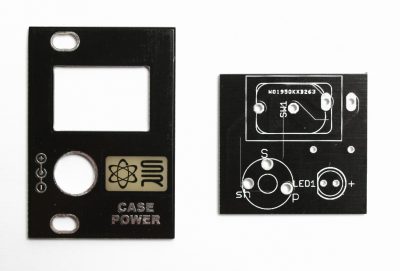
CASE POWER
Thank you for purchasing the Synthrotek Eurorack Case Power kit! This is an intermediate build. It is very important to get all the components properly soldered into the PCB in the correct placement. If you feel like you can handle it, please proceed! If not, get some help from a friend with experience or purchase a fully completed unit.
Attention: The molex connector and spade connectors on the Case Power are only for connecting to a distribution board(s). DO NOT connect a Case Power to another Case Power, Deluxe Power or Super Power via the molex connector or spade connectors. This WILL damage the power converters and void your warranty.
ATTN: Please follow the BOM and these instructions. Don’t populate from the PCB silkscreen or these instruction pictures alone. Our components may look different from the pictures, so please look over your parts and check the codes first.
LET’S BEGIN
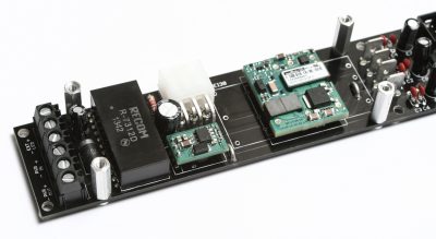
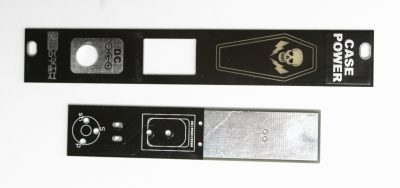
We will begin by assembling the main power supply PCB. This kit can be purchased with an optional 3U or 1U Eurorack panel, or it can be purchased with an LED and DC Jack. We will show those assembly instructions at the end of the page.

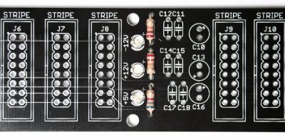
RESISTORS
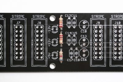
Resistors are not polarized so it doesn’t matter which way they are placed in, but it makes troubleshooting a lot easier if you line up all of the tolerance bands (usually a gold stripe) on the same side. Insert each resistor, matching the value to the proper spot as per the BOM.
Once they are all in there, carefully flip your project over and solder the resistors in place. Clip any excess leads.
LEDs
Now place the three 3mm LEDs into the PCB by aligning the longer of the two leads into the hole that is by “+” side on the board. Carefully flip your project over and solder the LEDs in place. Clip any excess leads.
CERAMIC CAPACITORS
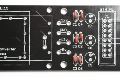
Up next are the ceramic capacitors. These aren’t polarized, so they can be inserted into the PCB in any direction. Once you get them all in there, go ahead and flip the project over, solder the legs, and clip any excess leads. An easy way to get these guys nice and flat is to only solder one leg of the capacitor first, then re-align it while reheating the solder pad.
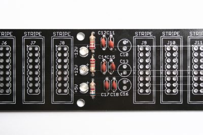
DIODES
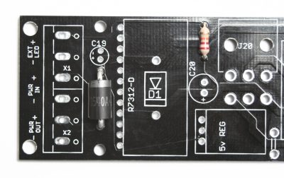
Populate D2, D1 is not used UNLESS you want to build an OPTIONAL VERSION: You can bypass the +12V regulator is you care to use a +12V DC Power Brick. All you need to do is use a short piece of 20-22AWG to jumper the Recom converter as show below. FOR NORMAL INSTALLATION PLEASE IGNORE and skip this step.
Make sure you hang on to the diode leads when you trim them! You will need them for later.
Diodes are polarized, so be careful to align the cathode stripe on the diode with the same cathode stripe on the silkscreen. When these are in place, you can flip the project over onto a hard flat surface, and solder them in place. Clip the excess part of the leads and put them aside for later.
+5 VOLTAGE REGULATOR
Populate the +5 voltage regulator as shown above and solder.
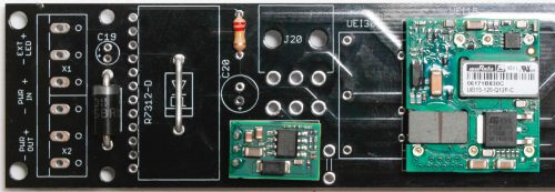
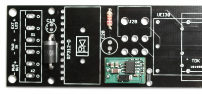
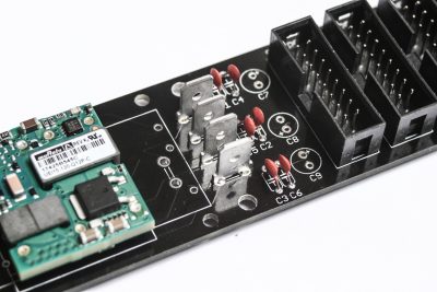
-12 VOLTAGE CONVERTERS
Case Power has three -12V regulator options:
- TDK for up to 500mA of possible current draw
- MuRata for up to 1.3A of possible current draw
- A larger MuRata for up to 2.5A of possible current draw
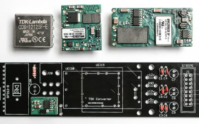
Each converter will fit in the PCB in only one way. For these instructions we will be populating the 1.3A MuRata converter, but rest assured the rest of the instructions will work perfectly with the TDK and the MuRata 2.5A.
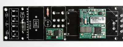
+12 VOLTAGE CONVERTER
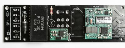
Populate either the RECOM R – 6212D or R – 7312D (they both have the same pin out and will fit onto the board where it reads “R7312-D”) into the PCB as shown above.
Please note: Sometimes the pins on the RECOM regulator need to be bent at an angle. To do this, insert the regulator as shown above, then BEFORE soldering, bend the regulator over until it can sit flush on the board with the pins in the holes. If you solder it in before you bend it, it will not be able to sit flush against the board.
Turn over and solder the converter in place. CAREFULLY use some small wire clippers to trim the leads (DON’T SCRATCH THE SOLDER MASK)
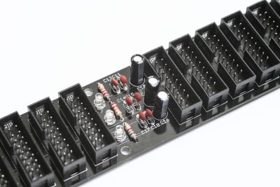
16-PIN EURORACK POWER HEADERS
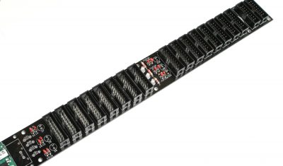
Populate the ten Eurorack 16-Pin keyed power connectors as shown above by aligning the keyed notch on the power connectors with the notch on the silk screen on the PCB as shown above. THIS IS VERY IMPORTANT!!! Now use a piece of cardboard or other flat surface to press against the headers and turn over and solder in place.
SPADE POWER CONNECTORS (Optional)
Included in your kit are four spade connectors if you plan on using Case Power with another manufacturer’s bus boards. These connectors do not need to be populated in order for the circuit to work. If you plan on using Synthrotek products only, you can omit this step. Synthrotek uses a safer MOLEX connector to connect extra distribution boards.
These spade connectors are not polarized and can be placed in and soldered from the other side.
MOLEX POWER CONNECTOR
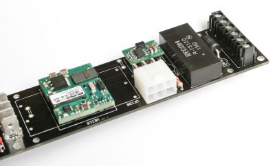
Now populate the MOLEX connector as shown above; turn over and solder in place.
ELECTROLYTIC CAPACITORS
Up next are the electrolytic capacitors. The electrolytic capacitors are polarized, so make sure when populating it that the longer lead goes into the hole with a “+” next to it. Once you have everything in place, go ahead and flip the project over and solder everything into place. Clip the excess leads.
SCREW CLAMP POWER HEADERS
The two 3-pin screw clamp power headers slide together to form a 6-pin header. Join them together and populate them, so that the holes on the screw clamp headers face the end of the board (NOT towards the diode). Turn the board over and solder them in place.
JUMPER WIRES
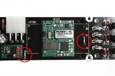
There are two places that you will need to add jumper wires to the circuit board depending on which -12V power converter you purchase. The jumper connection on the left is required no matter which converter you purchase. The jumper on the right needs to be populated if you purchased either the TDK 500mA Converter or the MuRata 1.3A Converter (shown above). If you purchased the MuRata 2.5A Converter, then this area will be covered up and you will not populate it. To do so, use the diode clippings you set aside, solder and trim. Note: do not use resistor clippings, they are not thick enough.
PROTECTIVE PANEL STANDOFFS
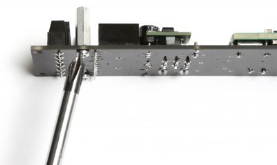
Screw on the four standoffs as shown above.
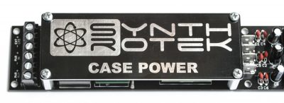
Now put the protective panel on the top of the standoffs and screw them down in place.
1U and 3U EURORACK PANELS (Optional)
If you purchased a 1U or 3U Eurorack panel kit, proceed with these assembly instructions. If you purchased a NO-PANEL kit, scroll down the page to those instructions.
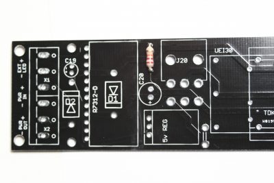
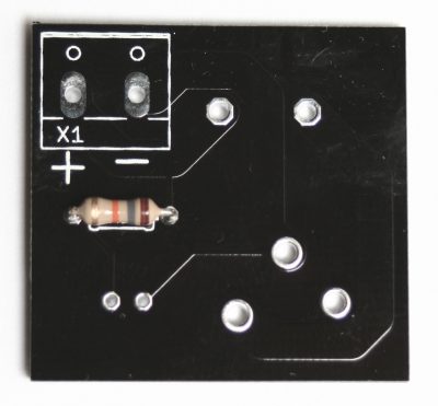
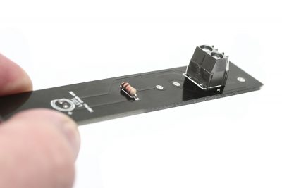
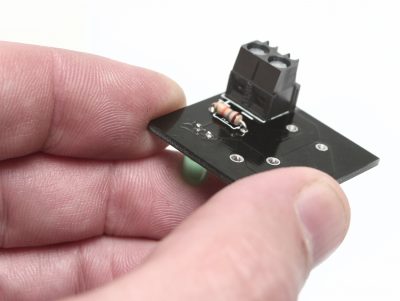
RESISTOR
Populate the resistor, turn the board over and solder it in place. Clip excess leads.
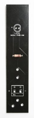
LED
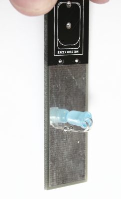
The LED is polarized and must be installed in the proper orientation. Make sure that the longer lead pokes through the PCB in the hole that has the “+” marking next to it. The 3U PCB has a reflective surface that will look best if you bend over the LED as shown below. Turn over, solder and clip.
Do not bend over the LED on the 1U PCB, just slide it in as shown below. Turn over, solder and clip.
SCREW CLAMP HEADER
Now populate the 2-Pin screw clamp header in the orientation as shown below. Turn over and solder in place.
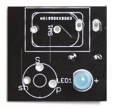
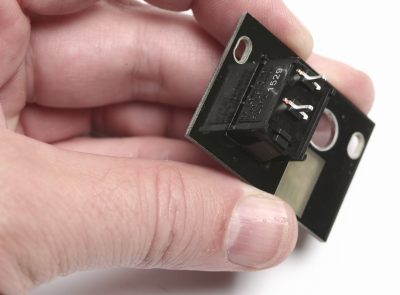
POWER SWITCH
Now snap in the power switch EXACTLY as shown below. It must be inserted this way to connect the PCB properly.
DC JACK
Populate the DC Jack (it will only fit one way) BUT DO NOT SOLDER JUST YET!
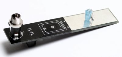
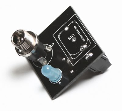
PANEL ALIGNMENT
Now place the panel onto the PCB by inserting the leads from the switch and the DC jack into the PCB. You can also tighten the DC jack nut down at this time (not overly tight). Take your time to make sure that the panel and PCB are parallel to each other. Once you feel confident, turn over and solder them into place. You are now done with the PCB assembly! Congrats! Now it is time to connect your panel to the main CASE POWER with the 16AWG wire included in your kit.
We recommend that you tin the tips of the wire before inserting into the screw clamp headers. Connect the 16AWG Red wire to both screw clamp headers (main board and front panel PCB) with the “+” next to it. Do the same for black (to the “-“) and tighten down. See photos below for reference.
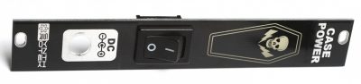
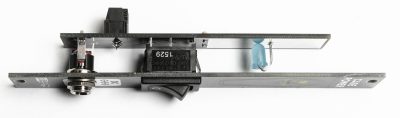
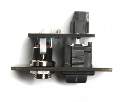
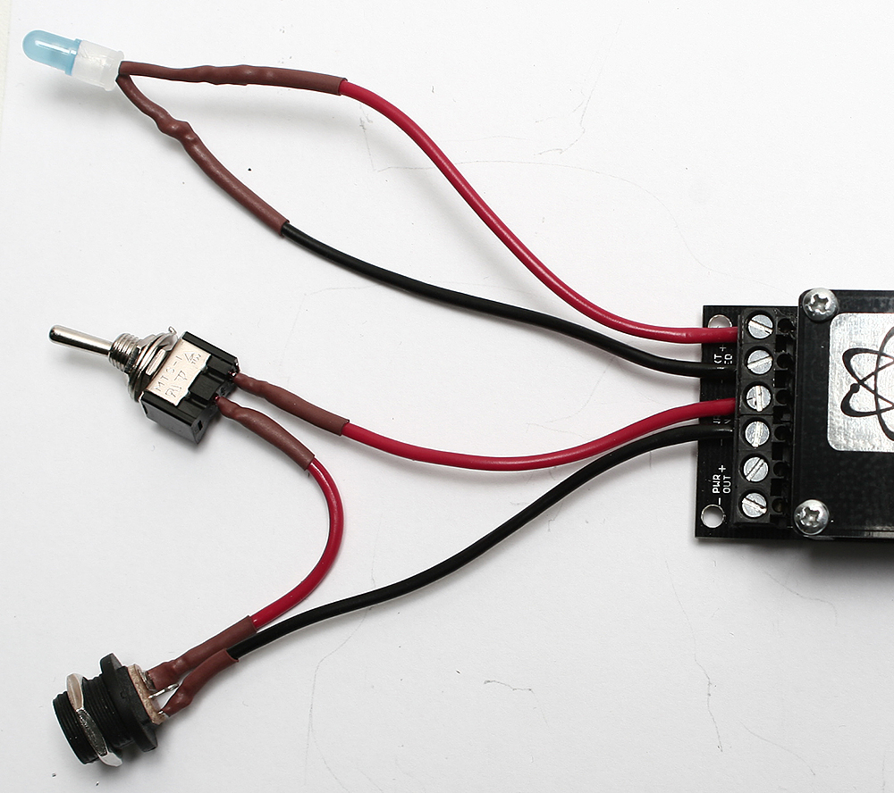
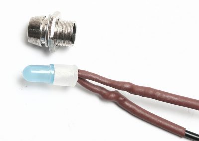
NO-PANEL JACK AND LED WIRING
If you purchased a kit with no Eurorack front panel please follow these instructions. Included in your kit is a DC jack, a toggle switch, some 16AWG wire, an LED, an LED Bezel with a plastic insert and some heat shrink tubing. These components are good for mounting into a case that is not very deep or if you plan on boring out wood holes etc to make these fit. If you are going to use the LED bezel, you will need to put the plastic insert on BEFORE you solder wires to the LED. Here are some photographs showing how you can wire these parts up.


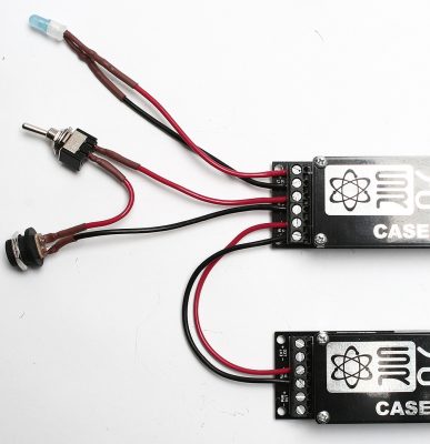
EXTRAS:
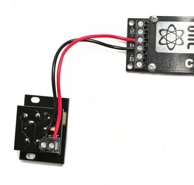
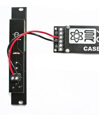
If you plan on powering 2 or more Case Powers with a single brick (make sure that your brick and cable gauge can handle the amp draw!), you can daisy-chain them using the Power IN and Power OUT screw clamp headers as shown below:
Attention: The molex connector and spade connectors on the Case Power are only for connecting to a distribution board(s). DO NOT connect a Case Power to another Case Power, Deluxe Power or Super Power via the molex connector or spade connectors. This WILL damage the power converters and void your warranty.
Testing Procedure
The following section is the testing procedure for the Case Power, and will ensure that your Case Power is fully functional.
Tools:
Volt Meter or Digital Multi-meter
Procedure:
Start by plugging your Case Power into a 19V power source. If all three LEDs turn on, that is a great sign. If one or more of them do not light up, immediately unplug your Case Power and check for solder joints that may look suspicious.
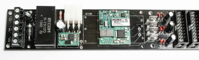
Once you have all three lights turning on, grab your volt meter and put the black probe on the spade connector marked GND. With the Case Power oriented so that the power section with the protective cover is on the left, touch the red probe of the volt meter to either of the very top pins of any of the 16 pin power headers. Your volt meter should read -12V. Then move the red probe down to the 5th pin, and your volt meter should read +12V. Once more, move the red probe down by just one pin, and it should read +5V. If you get any other readings from these pins, disconnect your Case Power immediately and check for a solder bridge or bad solder joint somewhere.
Lastly, do a quick visual inspection of your shrouded headers to make sure they are oriented correctly.