


Important Links
Quick Start & Tuning Guide
Product Page
Store Page
Assembly Instructions
Bill of Materials
Capacitor and Resistor Lookup Guide
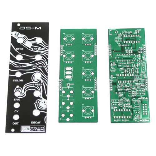
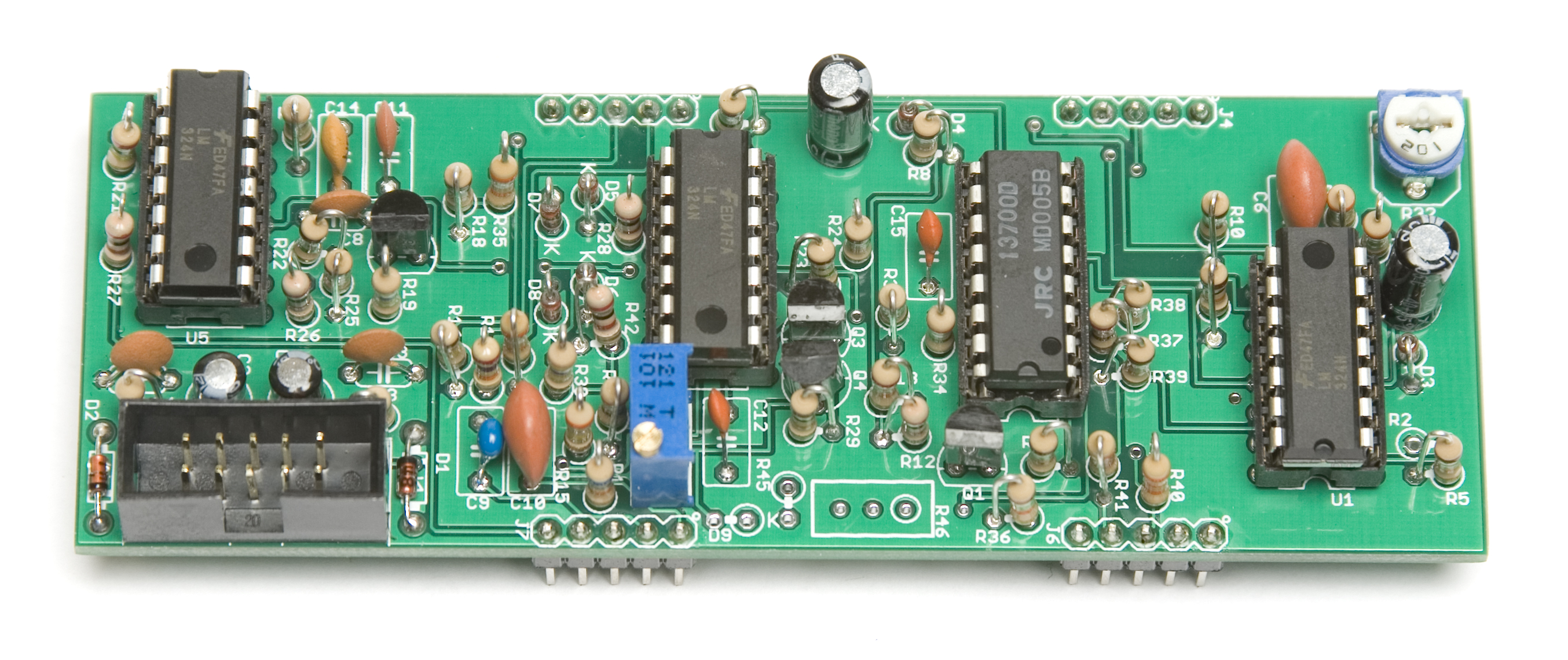
DS-M PCBs & Panel
Thank you for purchasing the DS-M Eurorack module! This is an intermediate to advanced build and not recommended for the beginner since it has a lot of tight fitted parts, stand up resistors and diodes. If you feel like you can handle it please proceed! If not, get some help from a friend with experience or purchase a fully completed unit.
ATTN: Please follow the BOM and these instructions and don’t populate from the PCB alone. Also sometimes we cannot get the exact pictured components, so please look over your parts and check the codes first. Lets begin with the MAIN Board.
FLAT DIODES
DS-M Flat 1N4148 Diodes
Start with the two flat 1N4148 diodes as shown aboce, then turn over on a firm surface to solder, then clip your leads. Diodes are polarized components so you must match the black stripe on your diodes with the white stripe on the PCB silkscreen.
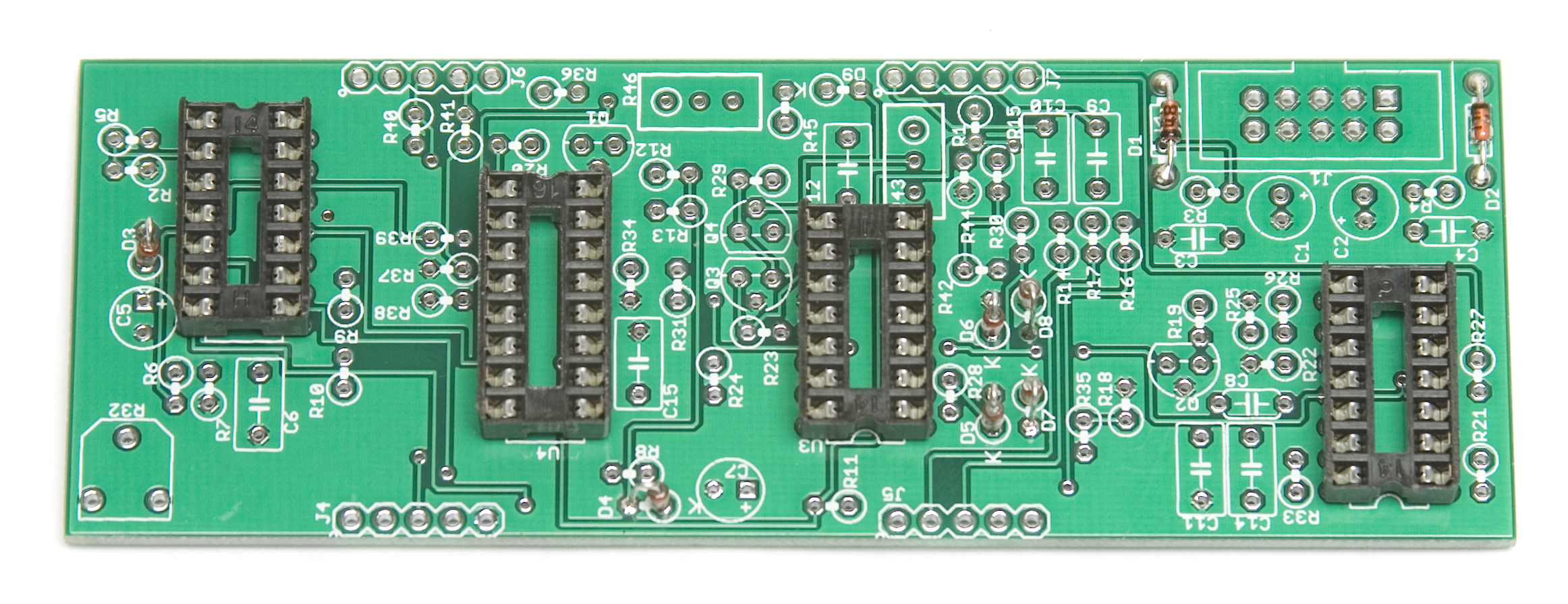
SOCKETS
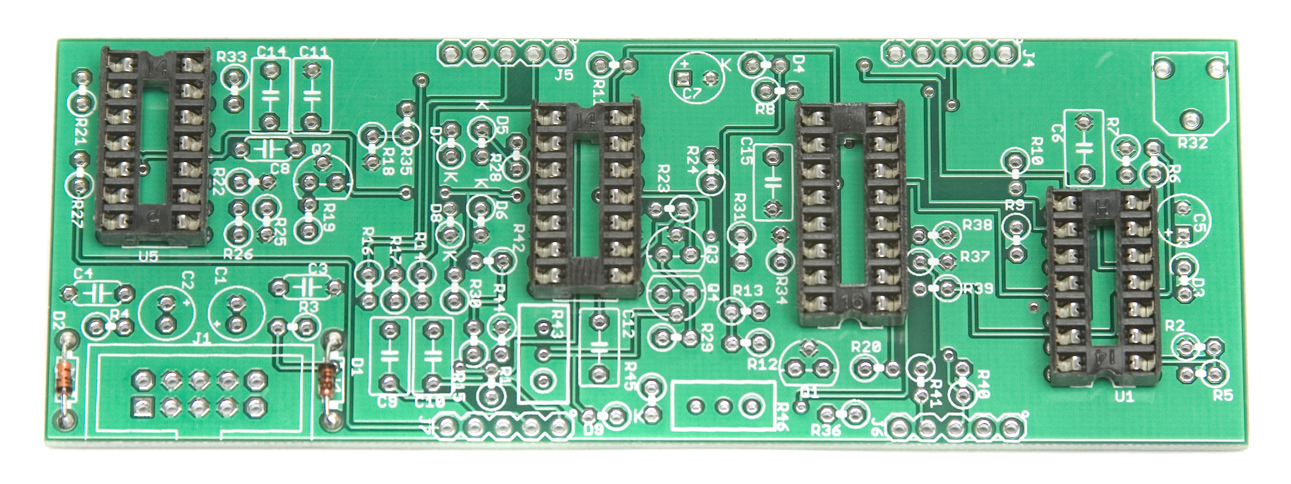
DS-M Sockets
Place the IC Sockets by aligning the notch with the notch graphic on the PCB Silk Screen. Turn over on a flat surface and solder into place.
REMAINING DIODES
DS-M Remaining Diodes
Populate the diodes, as shown above and below, then turn over on a firm surface to solder then clip your leads. Diodes are polarized components so you must align the black stripe on your diodes TOWARDS the larger circle on the silk-screen. In other words, place the black-striped side towards the via (hole) with the large circle. Keep in mind that you will not populate D9.
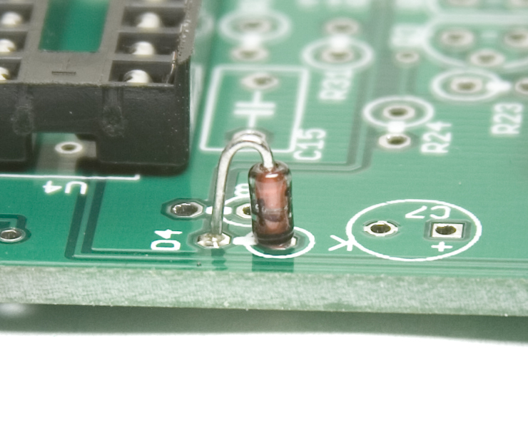
DS-M Diode Polarity
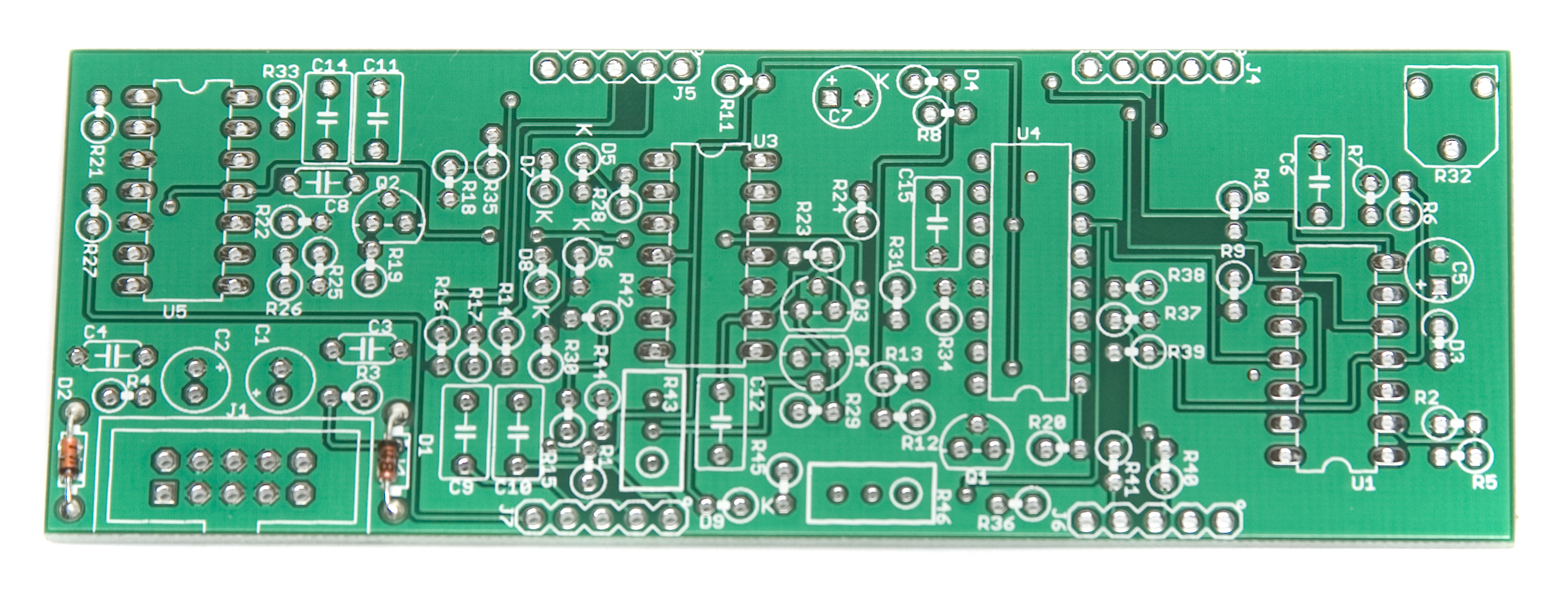
RESISTORS
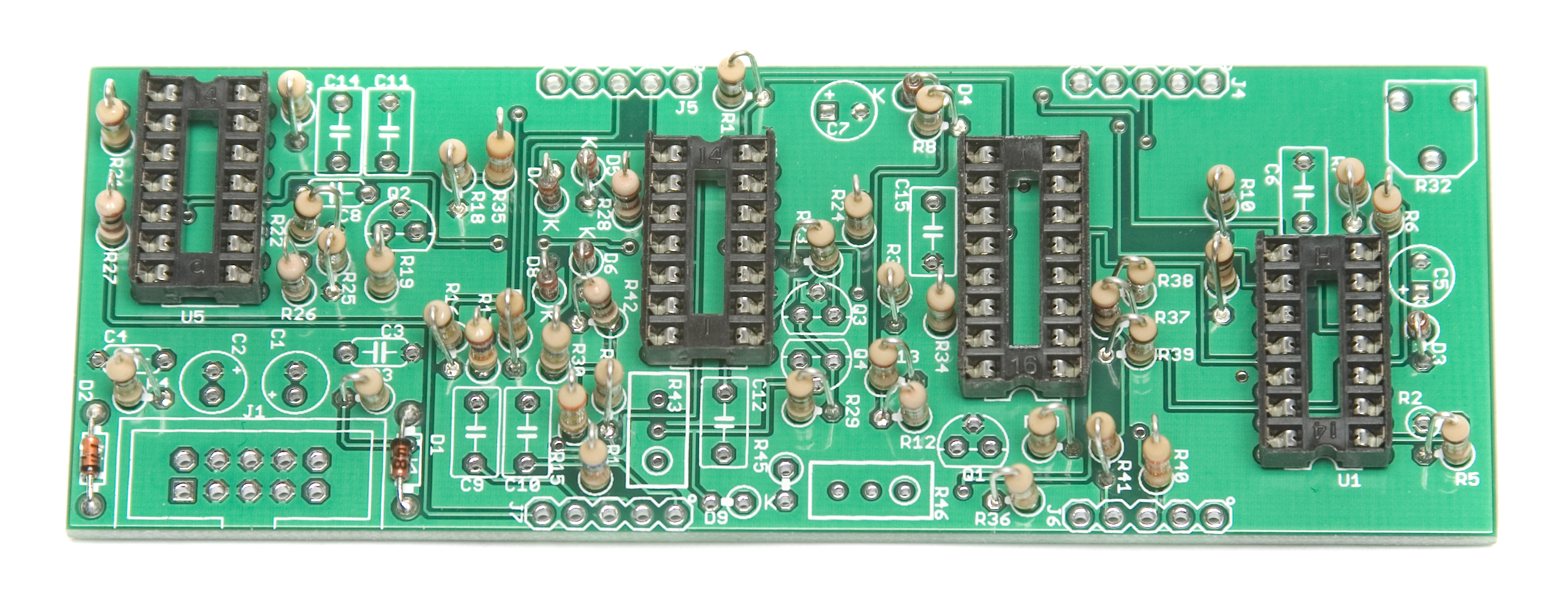
DS-M Resistors
There are quite a few resistors that need to be installed standing up. It is helpful to bend over one of the resistor leads first before populating each resistor. Solder and clip leads. Keep in mind that you will not populate R2 or R45 (ever).
CERAMIC CAPACITORS
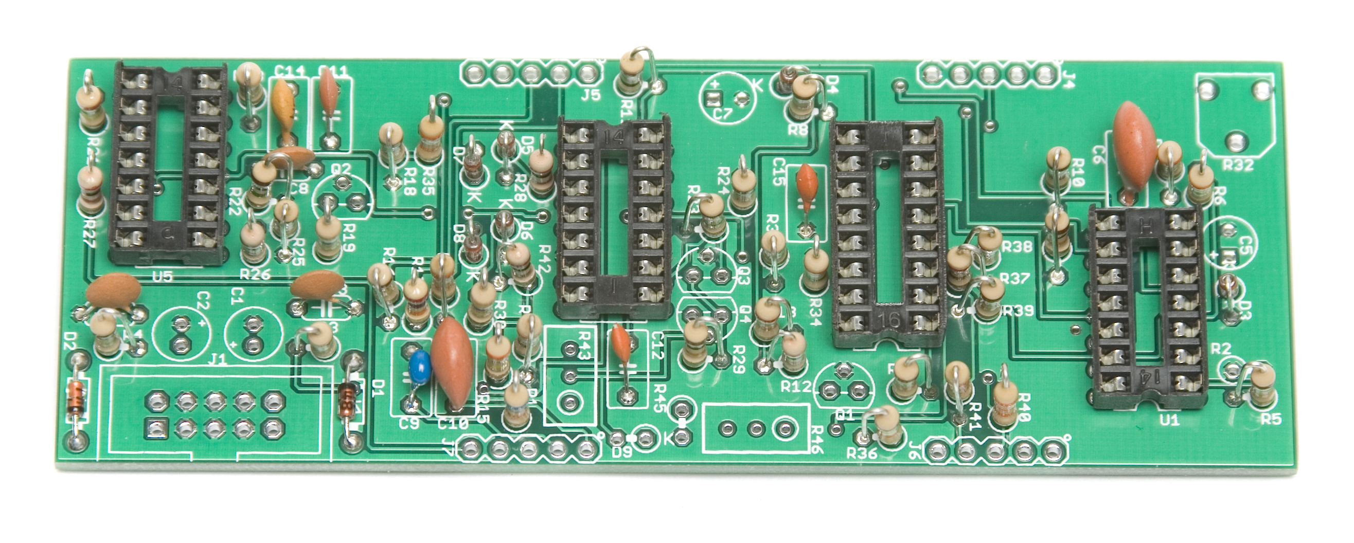
DS-M Ceramic Capacitors
Place the capacitors in place, solder and clip leads. These capacitors are not polarized so you don’t have to worry about orientation.
POWER CONNECTOR
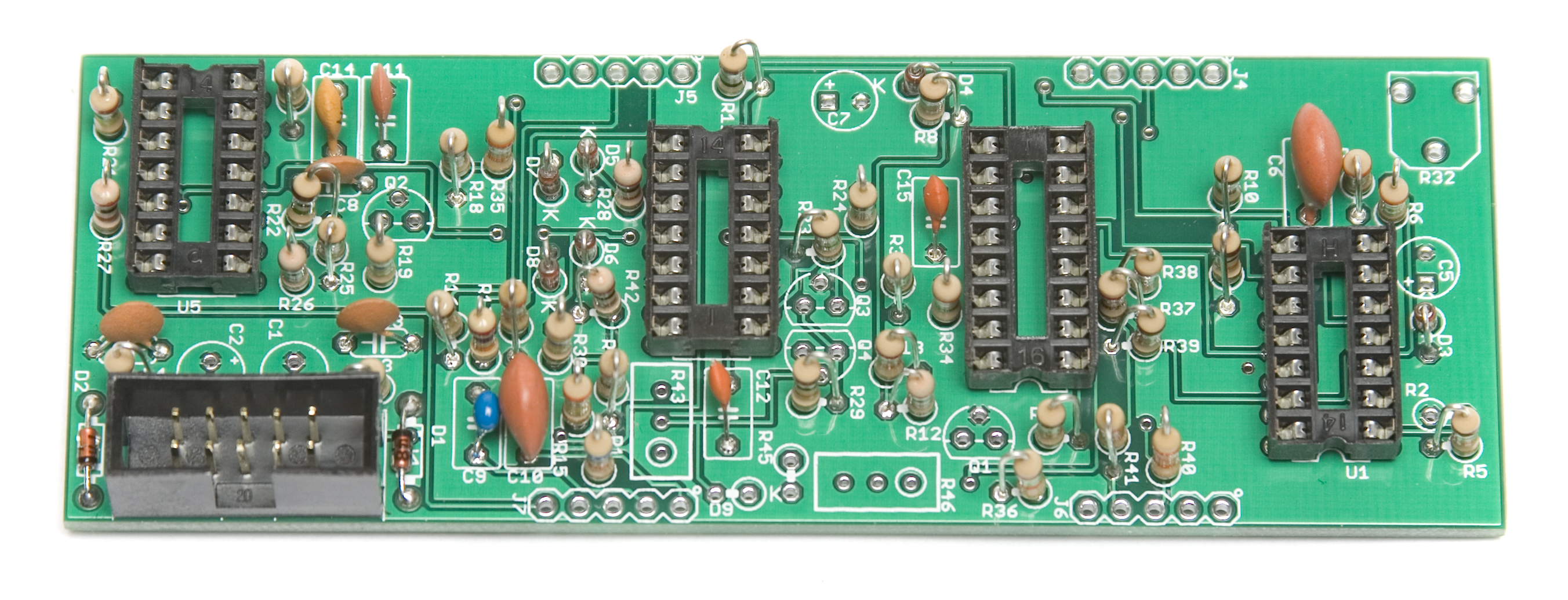
DS-M Power Conector
Next add the 10-Pin Eurorack Power Connector in place by matching the key notch with the key indicator on the PCB silk screen.
ELECTROLYTIC CAPACITORS & TRANSISTORS
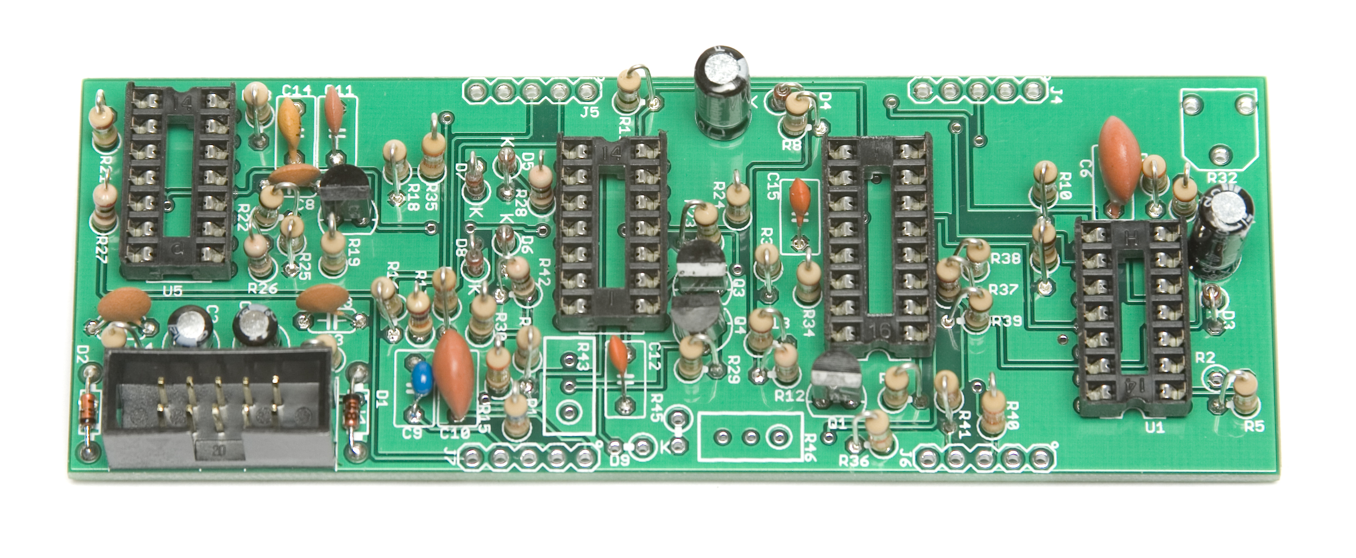
DS-M Electrolytic Capacitors and Transistors
Make sure you orient the electrolytic capacitors in correctly. The longer lead needs to be inserted into the hole that has the “+” marking near it. Solder and clip. Next add the transistors by matching the flat side of the transistors with the flat side on the silk screen. Turn over, solder and clip all leads.
TRIMMER POTENTIOMETERS
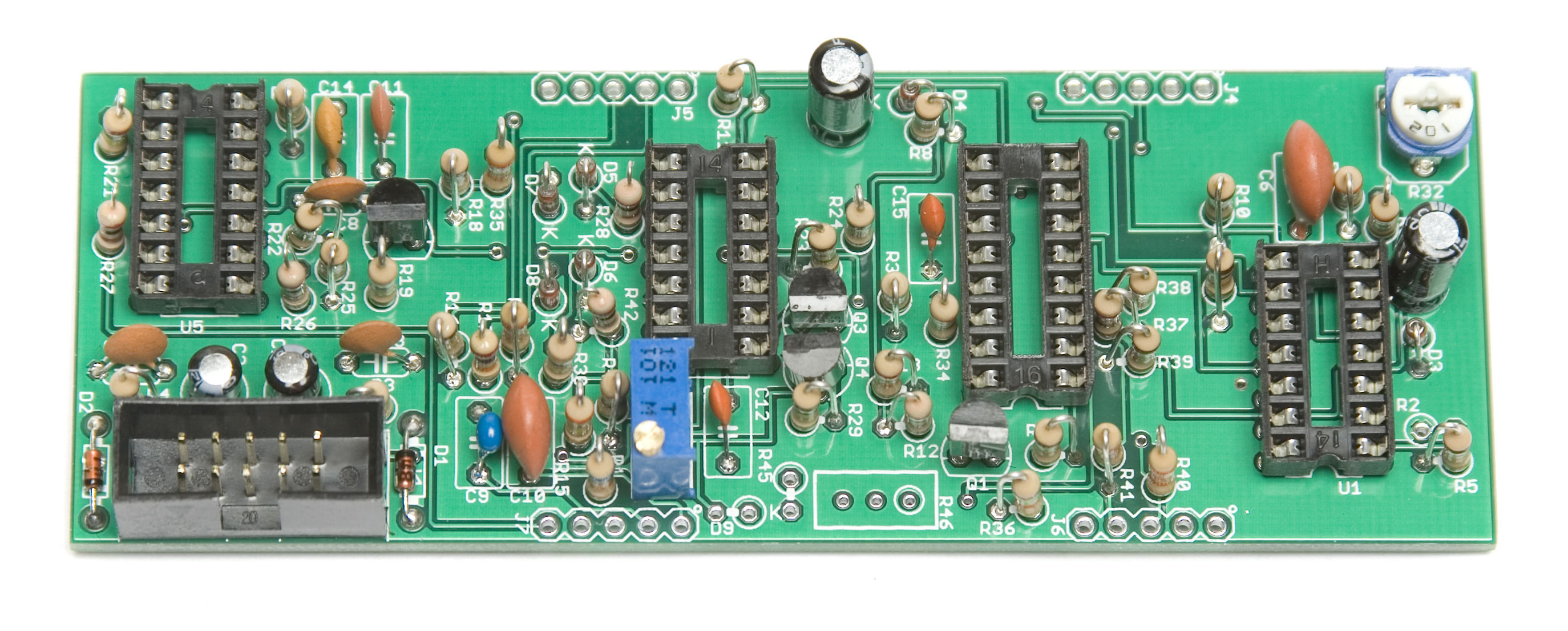
DS-M Trimmer Potentiometers
Now populate both trimmer pots on the PCB. Make sure the rectangular multi-turn timmer is oriented so that the screw is above the circle on the silk screen as shown above.
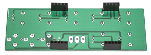
5-PIN MALE HEADERS
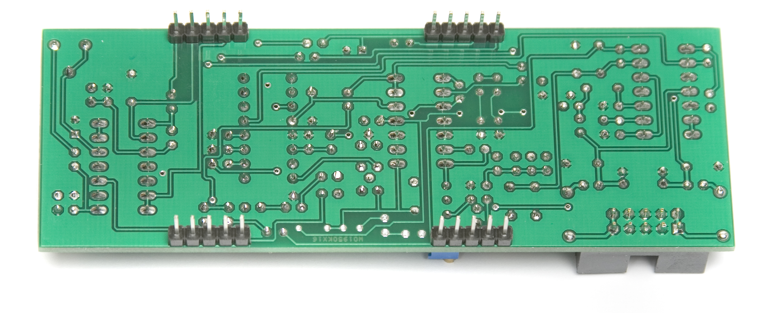
DS-M Connector Pins
Add the four 5-pin male headers as shown above, turn over and solder.
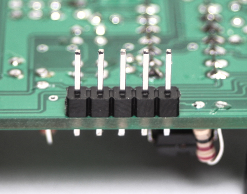
DS-M Male Headers
INTEGRATED CIRCUITS
DS-M ICs
Place the ICs in place by aligning the notch with the notch graphic on the PCB Silk Screen and notch on the sockets.
CONTROL BOARD
DS-M 5-Pin Female Headers
Set aside the MAIN board and now work on the CONTROL board by populating the four 5-pin FEMALE Headers. Turn over and solder.
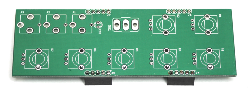
DS-M Female Headers
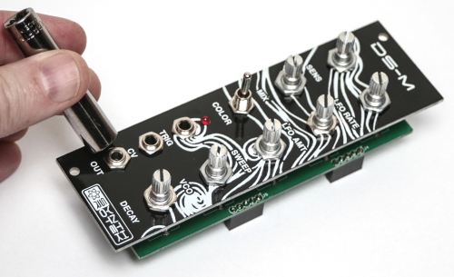
POTS, JACKS, SWITCH & LED
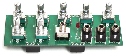
DS-M Pots, Jacks, Switch and LED
Populate the pots, jacks, switch and LED (Put the LONG lead into the pad closest to the board edge), BUT DO NOT SOLDER JUST YET!
DS-M Front Panel
BEFORE YOU SOLDER ANYTHING on the CONTROL board, carefully place the panel over the the control board and gently tighten the nuts in place.
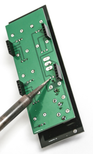
DS-M Soldering Control Board
Carefully turn over the CONTROL board over and now solder the jacks, pots, and switch. Next, push through the LED into the front panel and solder then clip leads. After you have soldered the components, turn the board over and gently tighten down the nuts again.
FINAL ASSEMBLY
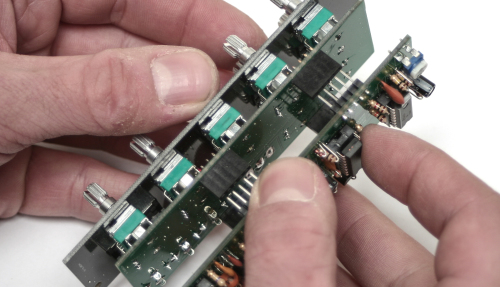
Connecting Main & Control Boards
Carefully marry the CONTROL board to the MAIN board as shown above. Try not to bend any leads.
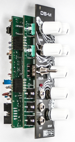
DS-M FINAL BUILD
Finally add the knobs and you are now done with your project and can test the unit in your eurorack system. If you have any questions or need help debugging, please first refer to our troubleshooting guide BY CLICKING HERE. If this gets you nowhere, please contact us by email for support. Thank you again for purchasing your kit from Synthrotek!
What’s the v/oct calibrating procedure?
Hey Ben, You can find the DS-M Quick start guide here: http://store.synthrotek.com/DS-M_Analog_Drum_Synth_Module_DIY_Kit. Its the second picture on that product listing, and the tuning procedure is at the bottom of that picture.
Thanks!
hey guys, i can’t source the ceramic 10uF cap required for C9, all caps i find are either smd or tantalum or electrolytic. i would like to use a electrolytic cap instead but i am not sure concerning the polarity. Any chance you could help me out how to orientate a 10uf electrolytic cap?
cheers ben (not the same on as above 🙂
This cap should be ceramic, not polarized. Mouser part number is in the BOM
is the 10uf ceramic cap available anywhere apart from mouser ?.it is the only component i don’t have and it is mad to pay the postage to EU for 1 cap.
Why use such an obscure unobtainium cap?
I have literally searched everywhere.Better to put a surface mount pad instead surely?
Very frustrating.
Hey There,
Unfortunately I’ve only found them through Mouser. You could always get one from us directly, and the shipping might be better than mouser. You can email us at store@synthrotek.com and we can chat about it there.
best,
-Patrick
Hi, is there a published schematic for this? Mine doesnt’t work and it’s difficult to troubleshoot without a schemo.
ty.
Hello,
We unfortunately cannot release schematics due to liscencing, contractual and other reasons. I would go through our Troubleshooting Guide, and ensure that all components are properly placed as per the Bill of Materials. If you need further assistance, you can email us at store@synthrotek.com and we can get you sorted out.
Best,
-Patrick at Synthrotek
Hi, any problem using metal film caps instead of ceramic? (10, 100, 220nf) Cheers 🙂
…and is LM13700d the same as LM13700n? Cheers!
Hey Tom,
We haven’t tried using metal film caps, but I don’t see them making a big difference. The only thing that will be affected is how the different noise settings sound, because those use the caps for filtering the audio through.
best,
-Patrick
either should work fine
-Patrick
Can I use a 100k log pot for R6 instead of 50k?
You probably could, but I’m not sure how it would affect the VCO. It would definitely make it more sensitive in the lower end of the pot, but I’m not sure what would happen when you turn the pot past the original value.
What does the trim pot R32 do? I didn’t see a reference to it in the calibration guide. Thanks!
Hi David, it controls the attack on the trigger input. For example, when I plug my piezo drum pad into the DSM, it sends a pretty faint signal. Turning up the Attack trimmer all the way makes it work perfectly.
Hello.
I have built the DS-M, but it does not work. In fact it does not even trig. I visually checked everything. The IC seem to be correctly powered by approximately 5.35 V.
I am stuck. Have you any suggestion, something I could check with my multimeter, as a starting point to fix this problem ?
Thank you.
Hi Marc, sorry to read, I would check out our trouble shooting guide first and see where you get: http://www.synthrotek.com/tech/troubleshooting-your-build/
Hi,
I would like to build the DS-M and have got the BoM yet. I also like to have the schematics, which I find quite handy. I get an idea of the circuit and more importantly, I find it essential for troubleshooting.
Thank you.
Sven, I hear you. We offer schematics on some of the products, but not all due to licensing agreements. We hopefully will be able to release more schematics soon!
What would greatly improve the product when you get to Mk II, would be to have a separate decay time for the Noise signal. I’d love it if I could have the noise decay quickly and the tone ring out longer. Having a second switch with say three decay times, or a knob that would set the decay noise in proportion to the main decay.
Alternatively, if I could have the noise on a normalled jack, such that if you don’t plug into the Noise out, it has the same decay as the tone, but if you patch the noise out into a VCA or LPG, it disables it from the main out.
Hi Steve, thanks for the suggestions! I will look back at this if/when we develop a Mk II DSM.