


Important Links
Product Page
Store Page
Assembly Instructions
Bill of Materials
Drill Template
Capacitor and Resistor Lookup Guide
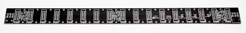
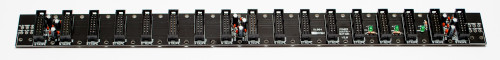
Eurorack Distro Board
Thank you for purchasing the Synthrotek Noise Filtering Eurorack Power Distribution Board. This is an intermediate build. You will need a fine tip soldering iron, a very steady hand and experience. If you feel like you can handle it, please proceed! If not, get some help from a friend with experience or purchase a fully completed unit.
ATTN: Please follow the BOM and these instructions and don’t populate from the PCB or these instruction pictures alone. Also sometimes we cannot get the exact pictured components, so please look over your parts and check the codes first.
Lets begin!
RESISTORS
Populate the 3 resistors then turn over on a firm surface to solder and clip leads.
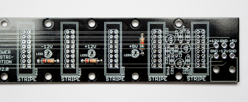
Distro Board Resistors
LEDs
LEDs are polarized components, make sure you place the cathode (shorter lead) into the pad with the flat side of the silk screen marking next to it. The flat side of the silk screen is the side adjacent to the callouts (LED1, LED2, LED3), so the shorter lead should go into the hole next to the callouts. Do this for all three, turn over to solder and clip leads.
Distro Board LEDs
16-PIN POWER CONNECTORS
Next add the 16-Pin Eurorack Power Connectors in place by matching the key notch with the key indicator on the PCB silk screen. Turn PCB over to solder. You can populate all of the connectors first then flip the board over with practice. This helps to keep the connectors flush to the PCB. There are a lot of pins to solder and this will take time. Make sure you do not leave your soldering iron on the pins too long and do not press down on the pins as this can damage the connector.
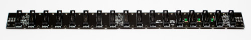
Distro Board 16-Pin Power Connectors
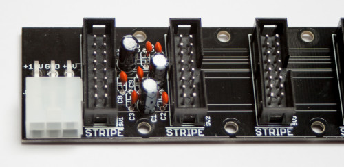
NOISE FILTERING CAPACITORS
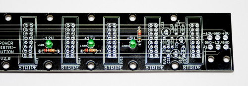
Place the ceramic and electrolytic capacitors in the PCB, solder and clip leads. Make sure you orient the electrolytic capacitors in correctly. The longer lead needs to be inserted into the hole that has the “+” marking near it.
Synthrotek has added these power conditioning / noise filtering caps in 3 places on our distro boards to filter both incoming power as well to reduce module to module noise on all 3 rails (+12, -12 and +5).
Distro Board Noise Filtering Capacitors
MOLEX CONNECTOR OR POWER WIRING
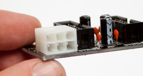
Distro Board Molex Connectors
You now have the choice to either use the Molex connectors or bare 16 AWG wire for connecting the distro board to other distro boards and/or the power supply module. If you are looking for a more permanent solution or do not want to use the Molex connectors just solder the wire directly to the PCB in their respective marked pads. Synthrotek has 3 ground connections, but if your supply or non-Synthrotek brand power modules have just one ground connection, feel free to just use the one. If you are using our Molex connection cable system, populate the right-angle Molex connectors to both ends and solder.
Final Distro Board with Molex
CONGRATS! you have now finalized your power distro board(s)! You can now connect your DC power and test out the boards. All 3 green LEDs should light up. If you are having any issues please consult our TROUBLESHOOTING GUIDE.
Thanks for choosing Synthrotek!
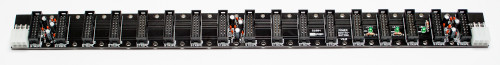
Final Eurorack Distro Board
Hi. I’ve got a few of these distro boards with the Deluxe Power 3U module. Am I able to use the 1U Power Panel (from the more recently released Case Power system) with this board? I want to free up the hp space and use my very empty 1U rail. Thanks!
Hello John,
The 1U power tile won’t work for the distro board. the 1U and 3U tiles are specifically for case power since that is a power module and a distro board.
Hi!
I have two finished noise filtering busboard and a super power green.
My 90w universal ac adaptor (I live in north america) is set to 15 volts. All the supporosed leds are lighting. The tested power on the two distros are:
+12 = 11.94 volt
+5 = 4.93 volts
-12 = -12.02
Is it ok if the +12 and + 5 rails supply just under the needed voltage?
Thanx!
Hello,
I recently completed my Noise-Filtering Power Distribution board. It seems to work perfectly, but I noticed that the CV pin is sitting at +5V with no modules connected to the board. Is this normal?
Thanks,
—-Dan
Hi Dan, what kind of solder did you use? If it is washable, I would certainly wash your board.
Far as I know it’s washable. I could do that, but I don’t measure a short (with my meter) between those two connections. What’s the normal level of CV supposed to be with power applied to the distribution board but no modules connected?
Hi Daniel, there should be no voltage on the CV bus unless you send something out on it.
Okay. I’ll look for a short. Thanks, Steve.
BTW, I HAVE seen this issue with unwashed boards, just a heads up
What size female molex connector is that? I have wires already that I plan to use but I don’t know what size of mal molex connector to buy along with crimp pins? Also, do the male 6-pin molex connectors that synthrotek sells come with crimp pins to input the wire?
Hey Antonio! here is the link to the female molex connector data sheet:
https://www.molex.com/en-us/products/part-detail/353180620?display=pdf
Yes, our male molex connectors come with 6 crimp pins each.
Hope this helps,
Lia