


Important Links
Product Page
Store Page
Manual
Assembly Instructions
Testing Instructions
Bill of Materials
Schematic
Capacitor & Resistor Lookup Guide
Thank you for purchasing the Synthrotek Quadrangle Kit! This is an advanced build. There is a lot of tight spacing, board to board connectors and solder pads that are close together. It is very important to get all the components properly soldered into the PCB in the correct placement. If you feel like you can handle it, please proceed! If not, get some help from a friend with experience or purchase a fully completed unit.
Please build according to the BOM, and not these instructions or the pictures alone. Some components may have changed since these were written, or we may not be able to get the proper components in the pictures.
Lets begin!
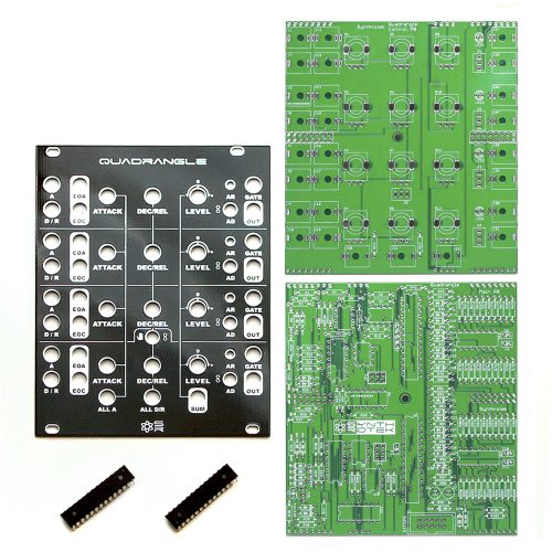
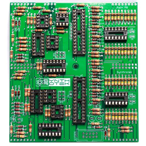
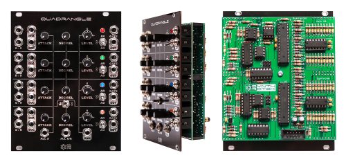
Synthrotek Quadrangle DIY PCB and PANEL with ICs
Diodes
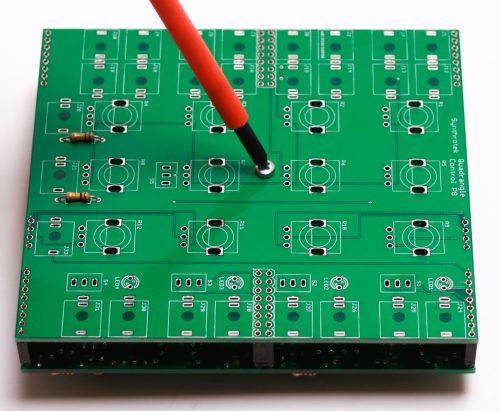
We’re going to start with the BAT85 diodes. These are polarized, so make sure when you are populating them to get the cathode band (black stripe) aligned in the same orientation as indicated on the PCB by the stripe. Once they are populated, flip the project over, and solder them in place, clipping the excess leads.
DIY Quadrangle Diodes
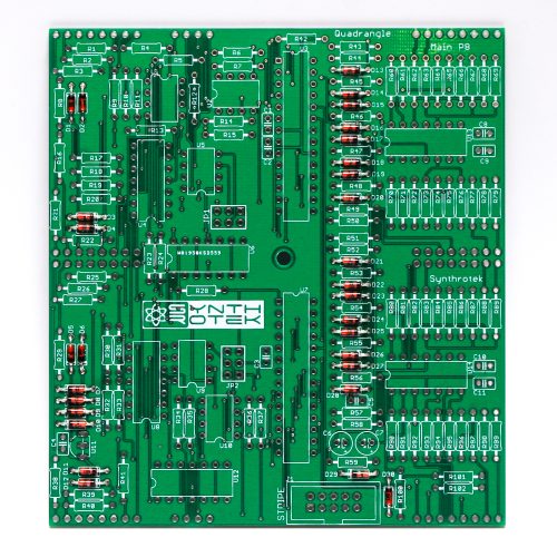
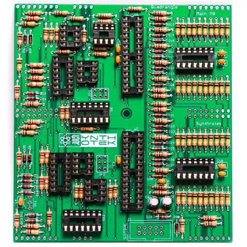
Resistors
Next, we are going to populate the resistors (on both the Control Board and the Main Board). Resistors are non polarized, so it doesn’t matter which direction you put them on the PCB, but it will help with any troubleshooting that may arise if you line up all the tolerance bands (usually a gold stripe) on one side. This will make it easier to read the color codes on the resistors.
Note: R13 and R14 on the control board are both 100k.
Once everything is in place, carefully flip your project over, and solder the components in place. Clip any excess leads on the bottom of the board.
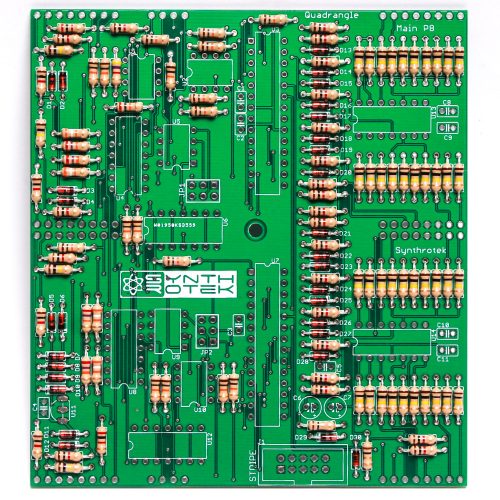
DIY Quadrangle Resistors
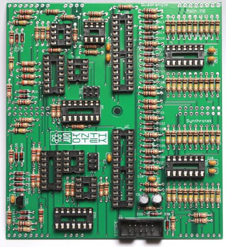
IC Sockets
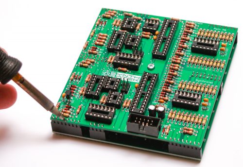
Next up are the IC sockets. Take care when populating these to not bend any of the legs, and to line up the notch in the end with the same notch that is displayed on the silkscreen. This notch indicates where pin 1 of the IC is. When you have them populated, carefully flip your project over and solder everything in place.
A trick to getting these nice and flat is to solder pins on opposite corners of the socket, and then reflow the solder joints while gently pushing on the top of the socket to seat it flat against the PCB. Then continue on and solder the rest of the pins, periodically checking for flatness.
DIY Quadrangle Sockets
Capacitors
Now we can populate the ceramic capacitors. These are non polarized, and can be inserted either direction. Once they are in, carefully flip over your project and solder them in place, clipping the excess leads.
Next up are the electrolytic capacitors. These guys are polarized, so take care when populating them. There is a small ‘+’ on the PCB that indicates where the longer of the two leads needs to go. When populated, the stripe on the capacitor should be facing away from the ‘+’ symbol. When you are happy with their placement, carefully flip your project over and solder everything in place, clipping the excess leads.
DIY Quadrangle Ceramic & Electrolytic Capacitors
ISP Headers, Power Connector and Voltage Regulator
The ISP Headers are next; populate, and solder on the other side.
Next up is the shrouded power header. Make sure when populating this that the notch in the header is lined up with the notch designation in the silkscreen. (it’s on the side closest to the edge of the PCB).
Next is the 9v regulator. This is polarized, so make sure when populating you align the flat edge of the component with the corresponding flat line on the silkscreen.
DIY Quadrangle Voltage Regulator and Power Connector
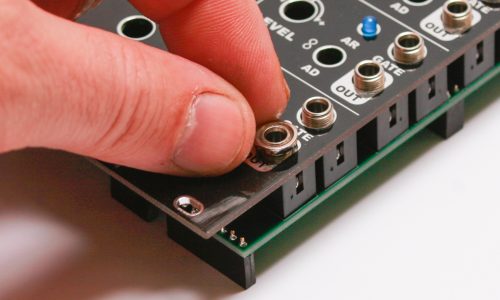
Board to Board Connectors
First take the metal standoff and secure it to the Main Board with one of the standoff screws:
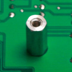
Standoff Placement
Take all of the board to board header connectors and put them together like this:
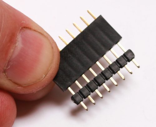
Board to Board Connectors
Next, turn over the Main Board and place them into the PCB (the male side first) like this:
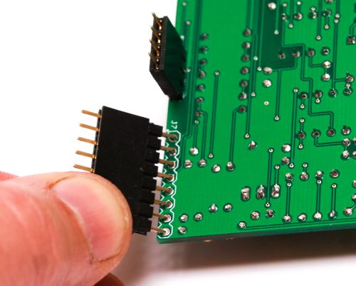
Placing Board to Board Connectors
The Main Board should look like this now:
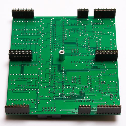
Main Board with Headers
Take the Control Board and carefully place it over the header pins:
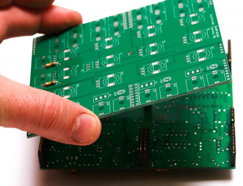
Control Board Placement
Now take the other standoff screw and secure it to the Control Board:
Securing Standoff Screw
Carefully turn the board over and solder all of the board to board connectors in place. Carefully turn over AGAIN and solder the control board side.
It is HIGHLY RECOMMENDED that you reflow the joints on the Control Board. Once the rest of the Control Board’s components are in place, it will be very difficult to do any rework on this board if you end up having a cold solder.
DIY QUADRANGLE Board to Board Connector Soldering
NEXT remove the Standoff screw from the Main Board and CAREFULLY pull the Control Board and the Main Board apart. Then remove the standoff from the Control Board.
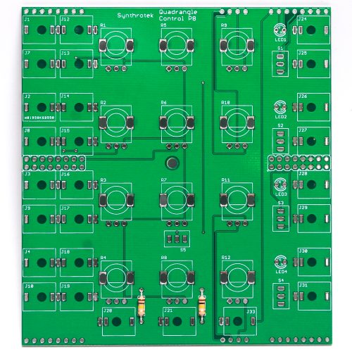
JACKS and LEDs
Now populate all of the jacks in place and also the LEDs. LED’s are polarized and need to have the flat side the LED match the flat side on the PCB silkscreen! DO NOT SOLDER ANYTHING YET!
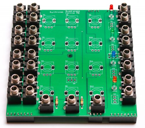
DIY QUADRANGLE Jacks and LEDs
Once everything is in place (but not soldered!), carefully set the front panel down over everything.
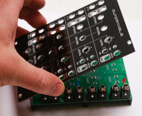
DIY QUADRANGLE Panel Placement
Next, hand-tighten nuts on a couple of the jacks (just barely!), one jack on each side of the board. Turn over and push the LED’s through the hole (or keep them recessed if that is how you roll) and solder the jacks and LEDs in place.
DIY QUADRANGLE NUTS
Standoff, Switches and Potentiometers
Remove the panel.
Now take the standoff and screw it in place on the CONTROL BOARD.
Standoff Placement
Now populate the four SPDT (on-off-on: 3 position) switches on the right hand side row and the ONE SPDT (on-on: 2 position) switch in the lower middle of the board. Next add all of the Potentiometers.
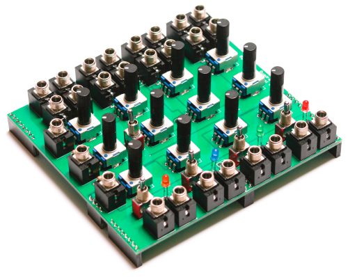
DIY QUADRANGLE Switches and Pots
Final Panel Placement
Add the front panel for the last time (yeah!) and secure down (again carefully) the nuts everywhere. Grab your favorite tool (pliers not recommended!) and tighten down the nuts (just barely!). If you are using a socket, tape the end of the socket so that you don’t scratch the panel. Turn the project over and solder the switches and pots into place.
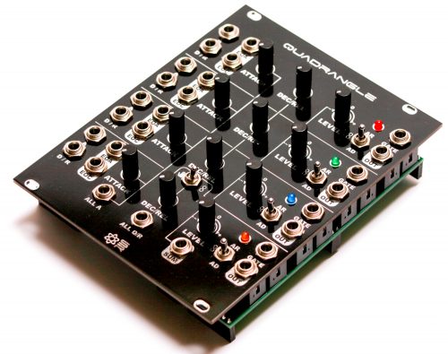
DIY Quadrangle Final Panel Placement
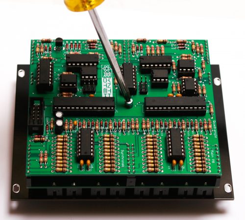
Connecting the Boards and ICs
CAREFULLY! (as to not bend any pins) connect the Control Board to the Main Board together.
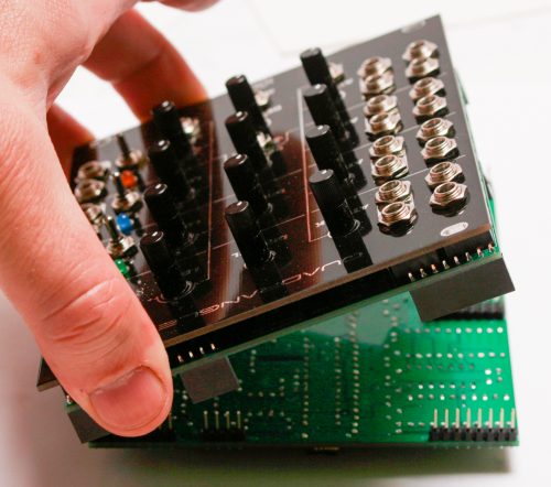
DIY QUADRANGLE BOARD CONNECTION
Finally, insert the ICs into their sockets. You will need to bend the legs inward a little to make them fit. Make sure that all the legs are firmly seated in the socket and that the notches on the ICs match the notches on the sockets! If there is no notch on the IC then match the side that has the dot over pin one of the IC in the side of the socket that has the notch.
Lastly, add that final standoff screw and secure the boards together.
DIY QUADRANGLE ICs and final screw
Take a good look over your project to make sure that you did not insert any ICs backwards or miss a solder. If you are all good to go, connect the module to your power supply and get patching!
Final DIY Quadrangle Assembly
Testing Instructions
Let’s make sure your Quadrangle is working correctly.
You will need a Eurorack system with:
- A CV source
- A gate or trigger
- An oscillator
- A VCA
With your Eurorack system powered off, plug the Quadrangle into your eurorack power via the included 10 to 16 pin power cable. Then power your system on.
Checking each channel
The Quadrangle has four envelope channels. Check each channel with the following instructions.
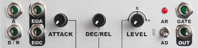
Here is what channel one looks like:
- Flip the global Stop/Loop switch (near the center of the module) to the right, or Loop.
- Patch the OUT of channel one into your VCA CV input jack.
- Patch your oscillator into your VCA Audio input jack.
- Patch your VCA output to a mixer/headphones/etc.
- Patch a cable into into the GATE jack of channel one. Let the other end dangle.
- Flip the channel’s switch to center, or Loop mode. The channel should start self-cycling. It shouldn’t be triggered by the previous Quadrangle’s end of cycle (channel four).
- Turn the LEVEL pot fully clockwise. Turn the ATTACK and DEC/REL pots fully counterclockwise. The Quadrangle has a very short minimum speed of 2ms, so it will sound pretty fast!
- Turn the ATTACK and DEC/REL pots to the 12 o’clock position. The LED should get brighter during the attack cycle and dim during the decay/release cycle.
- Plug a CV source into the A jack. This CV source is additive; it should affect the attack cycle. Now do the same for the D/R jack; this should affect the decay/release cycle.
- Plug the EOA (end of attack) jack into a gate. You can use one of the other Quadrangle GATE jacks for this. When the attack cycle has finished and the LED reaches full brightness, the EOA jack should trigger the channel. Now check the EOC (end of cycle) jack the same way; at the end of the envelope cycle, the EOC jack should trigger the channel.
- Now patch your gate/trigger source into the GATE jack. Move the channel switch to AR; the channel will stop self-cycling. Send a gate/trigger to the channel; it should trigger the channel. Switch to AD and send a gate/trigger again; this should trigger the channel as well. (Note: when the switch engages the Loop function, even momentarily, it will trigger the channel.)
Checking the global Stop / Loop
![]()
The global Loop control is different than the channel Loop. While the channel Loop allows each channel to self-cycle independently, the global Loop triggers channel one when channel four’s cycle is complete. When it is switched to Stop, channel four will not trigger channel one.
- Remove any cables patched into the GATE inputs. Move the global switch to Stop. Switch all four channels to either AR or AD. Once the current cascades have completed, all envelopes will stop triggering and cascading.
- Move channel four’s switch to Loop. When channel four completes, it should not trigger channel one.
- Move the global switch to Loop. When channel four completes its cycle, it should now trigger channel one.
Checking the summed outputs
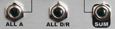
- Plug a CV source into the ALL A jack. This CV source should manipulate the attack on all four channels.
- Plug a CV source into the ALL D/R jack. This CV source should manipulate the decay/release on all four channels.
- Patch the SUM jack into your VCA. This jack should sum together all the envelope outputs, whether they are functioning simultaneously or one at a time.
CONGRATS! You just built a gigantic module. Now go make some great music!
And if you want to get more info on the Quadrangle and how its cascading works, check out the Manual here.