


Important Links
Product Page
Store Page
Assembly Instructions
Bill of Materials
Quick Start Guide
Capacitor and Resistor Lookup Guide
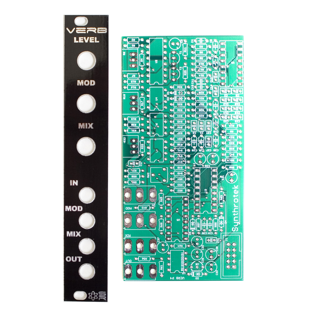
Thank you for purchasing the Synthrotek Verb Kit! This is an advanced build. There is a lot of tight spacing, and solder pads that are close together. It is very important to get all the components properly soldered into the PCB in the correct placement. If you feel like you can handle it, please proceed! If not, get some help from a friend with experience or purchase a fully completed unit.
Please build according to the BOM, and not these instructions or the pictures alone. Some components may have changed since these were written, or we may not be able to get the proper components in the pictures.
Lets Begin!
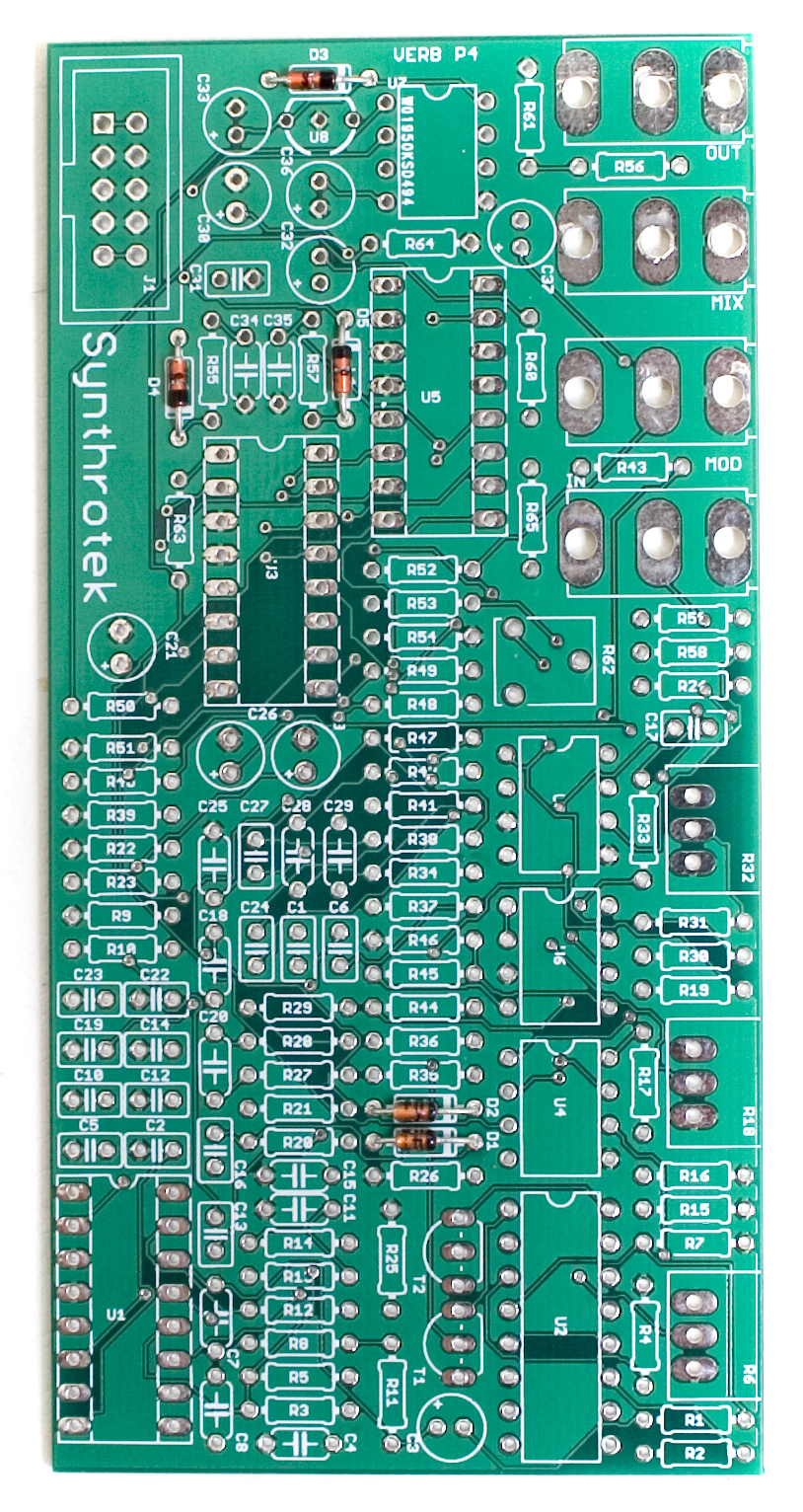
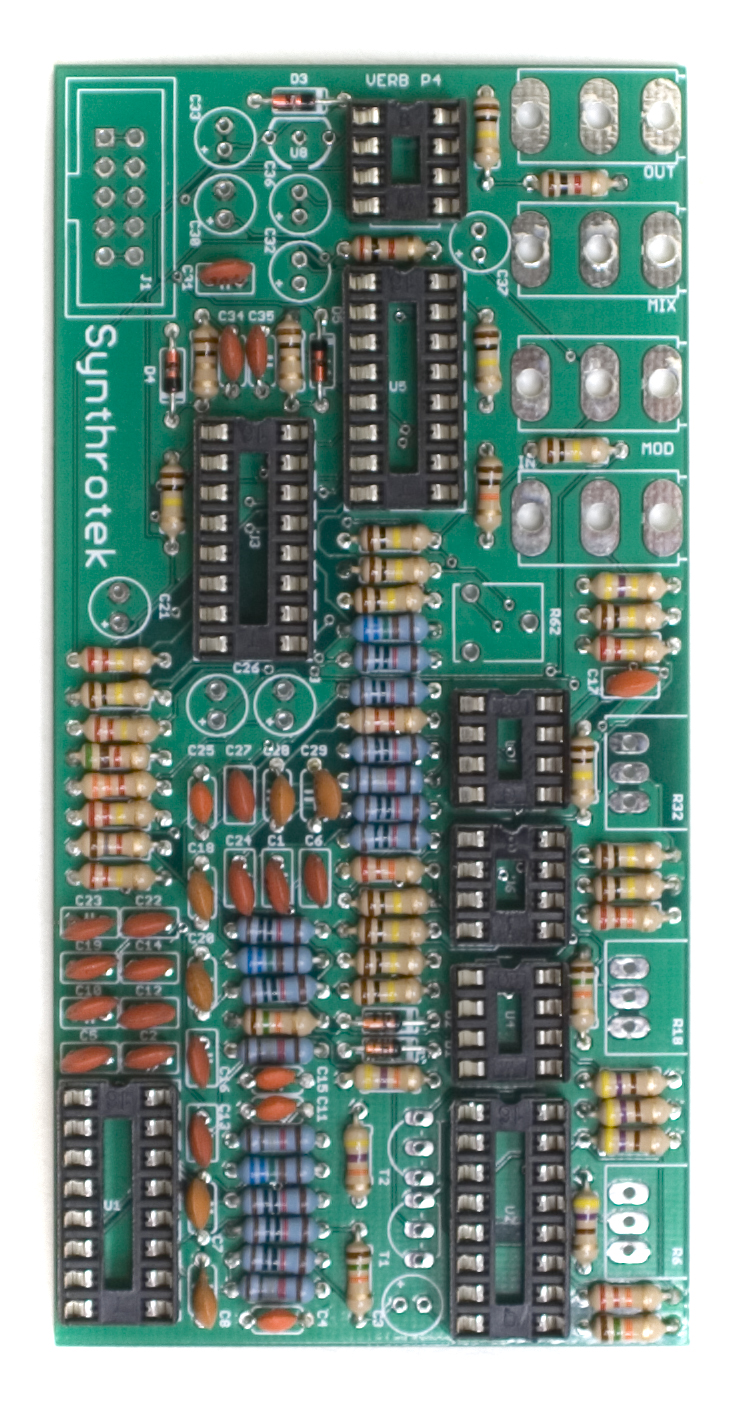
Diodes
We’re going to start with the diodes. This project has two different kinds of diodes, so pay attention to the BOM and make sure they are in the correct spots. These are polarized, so make sure when you are populating them to get the cathode band (black stripe) aligned in the same orientation as indicated on the PCB by the stripe. Once they are populated, flip the project over, and solder them in place, clipping the excess leads.
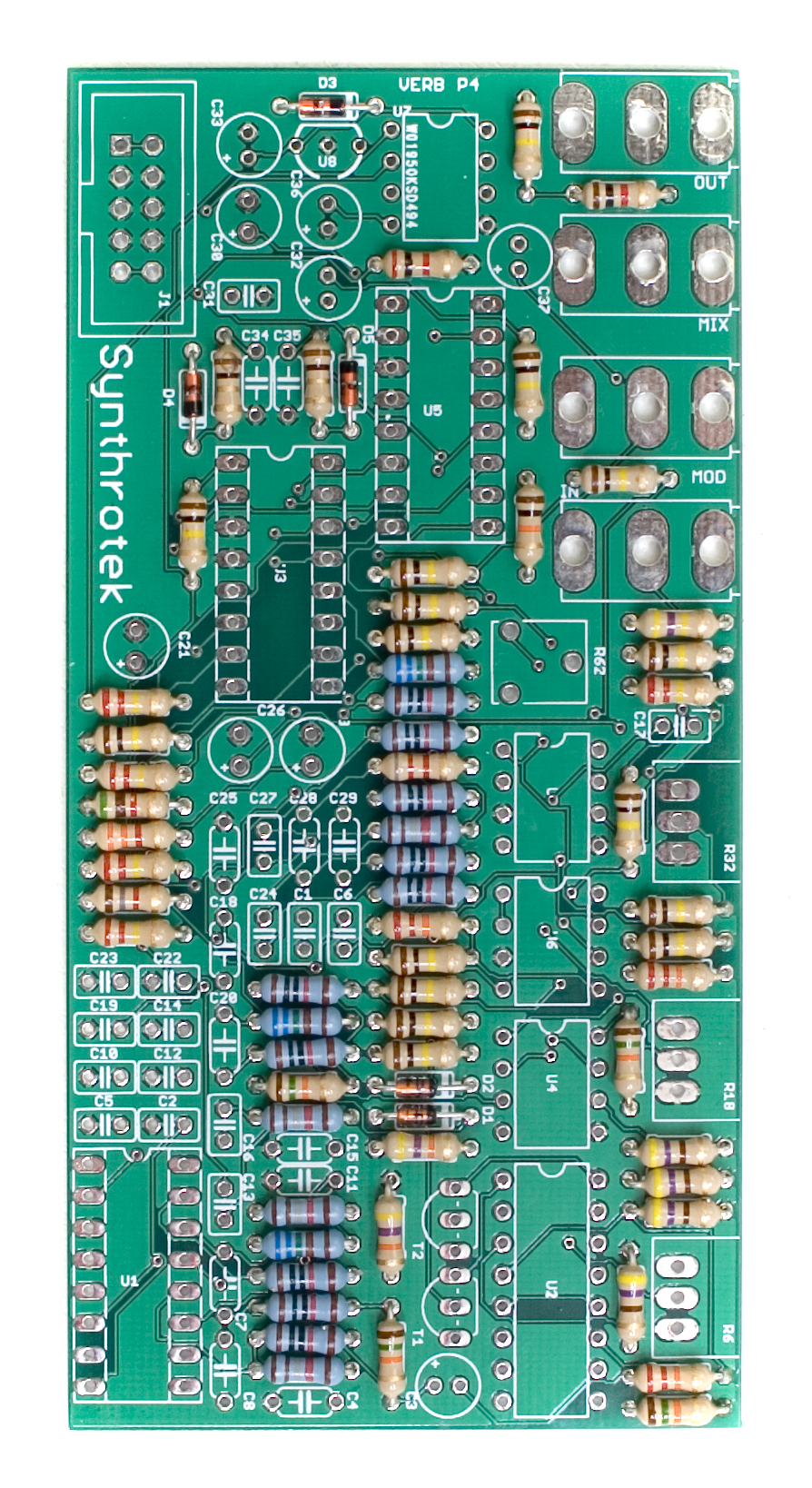
Resistors
Next, we are going to populate the resistors. Resistors are non polarized, so it doesn’t matter which direction you put them on the PCB, but it will help with any troubleshooting that may arise if you line up all the tolerance bands (usually a gold stripe) on one side. This will make it easier to read the color codes on the resistors.
Once everything is in place, carefully flip your project over, and solder the components in place. Clip any excess leads on the bottom of the board.
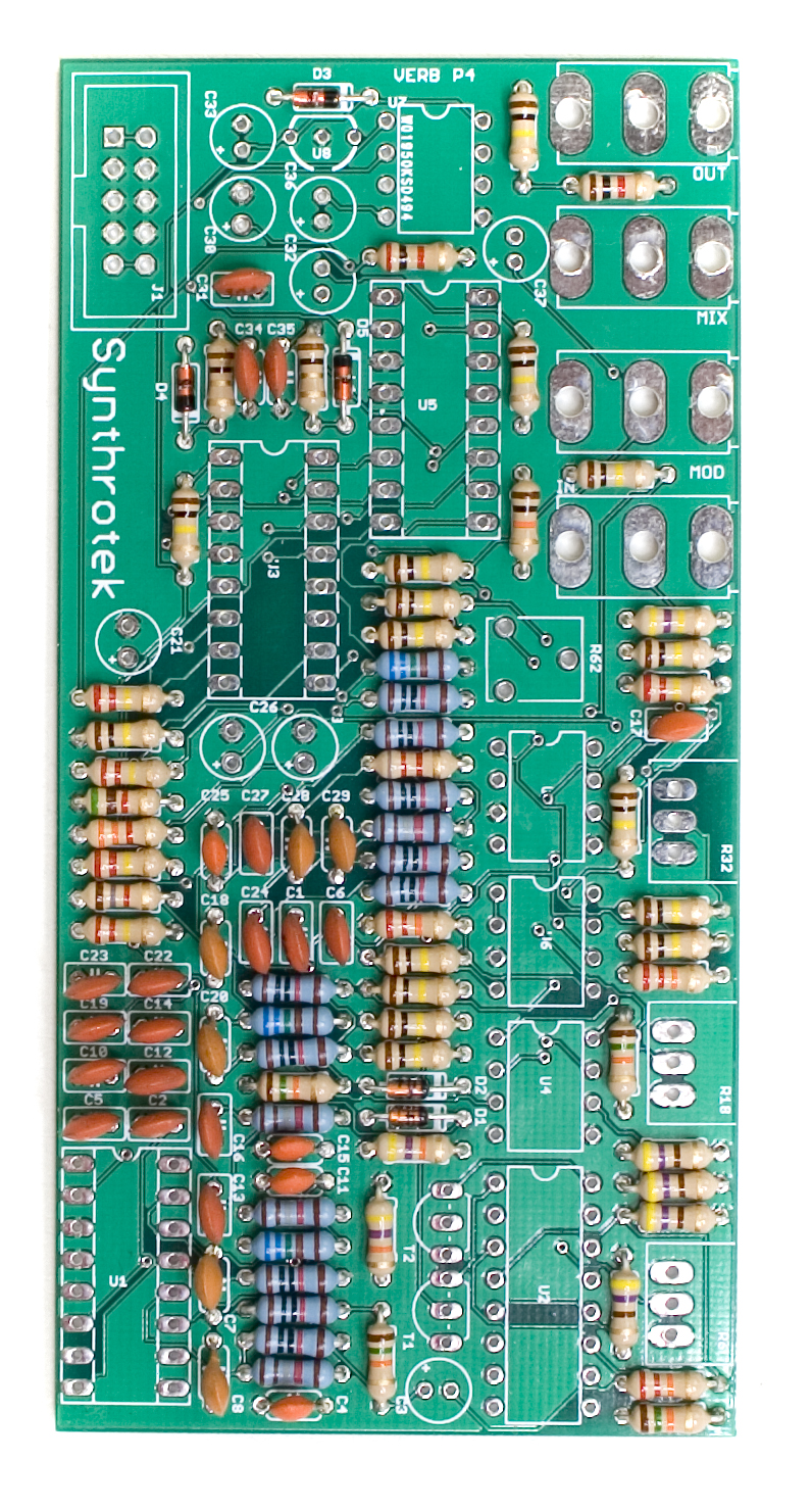
Ceramic Capacitors
Now we can populate the ceramic capacitors. These are non polarized, and can be inserted either direction. Once they are in, carefully flip over your project and solder them in place, clipping the excess leads.
IC Sockets
Next up are the IC sockets. Take care when populating these to not bend any of the legs, and to line up the notch in the end with the same notch that is displayed on the silkscreen. This notch indicates where pin 1 of the IC is. When you have them populated, carefully flip your project over and solder everything in place.
A trick to getting these nice and flat is to only solder one or two pins of each socket, and then reflow the solder joint while gently pushing on the top of the socket to seat it flat against the PCB. Then continue on and solder the rest of the pins, periodically checking for flatness.
Transistors, Voltage Regulator and Trimmer Potentiometer
Next up are the two transistors, and the 5v regulator. These are all polarized, so make sure when populating them that you align the flat edge of the component with the corresponding flat line on the silkscreen. Also pay close attention to the number on the side of the component, as it is very easy to mix up the voltage regulator with the transistors, as they all look alike.
When populating the trimmer potentiometer, orient the flat side (the side with two legs) up with the matching side on the PCB. (opposite the callout)
Once everything is in it’s proper place according to the BOM, carefully flip your project over and solder everything in place, clipping any excess leads on the bottom.
![]()
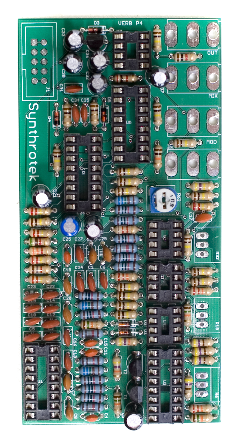
Electrolytic Capacitors
Next up are the electrolytic capacitors. These guys are polarized, so take care when populating them. There is a small ‘+’ on the PCB that indicates where the longer of the two leads needs to go. When populated, the stripe on the capacitor should be facing away from the ‘+’ symbol. When you are happy with their placement, carefully flip your project over and solder everything in place, clipping the excess leads.
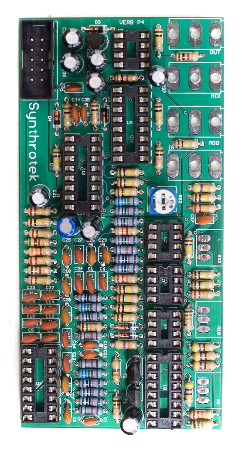
10 Pin Power Header
Next up is the shrouded power header. Make sure when populating this that the notch in the header is lined up with the notch designation in the silkscreen. (it’s on the side closest to the edge of the PCB).
When you’re sure that it is oriented correctly, carefully flip your project over and solder it in place. You can use a similar trick as the IC sockets to get this header to sit flat as well.
Potentiometers and Jacks
Next up are the potentiometers and jacks. Start by populating them and carefully flipping the whole thing over. Solder ONLY ONE LEG of each pot and each jack. (We recommend the middle leg on the pots, and the far back leg of the jacks)
Once they are all soldered by the single leg, go back and gently apply pressure to each one while re-heating that solder joint. This will sit the components flat to the PCB.
Don’t solder the rest of the legs yet!
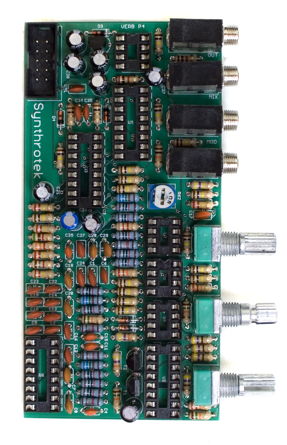
Front Panel Placement
Now we can place the front panel over the control components that were soldered in earlier. Carefully align the front panel and sit it down on the components, as shown below. Then hand tighten the nuts on the front panel to hold it in place.
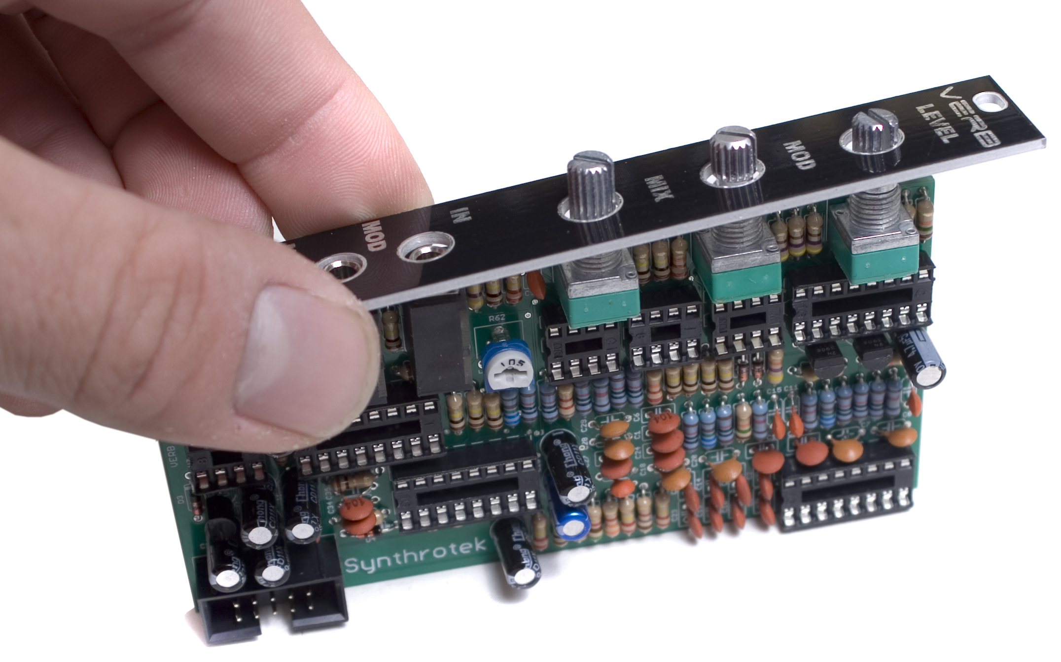
When you have the front panel on, hold the project up so that you are looking at it from the side, and make sure that the front panel is at a 90 degree angle to the PCB, and that pots and jacks are nice and straight.
When you are satisfied with everything, solder the remaining pins on the control components. Clip the excess on the jacks and pins. (It’s recommended to use a larger, or more robust set of clippers, as the pins on the jacks are quite large.)
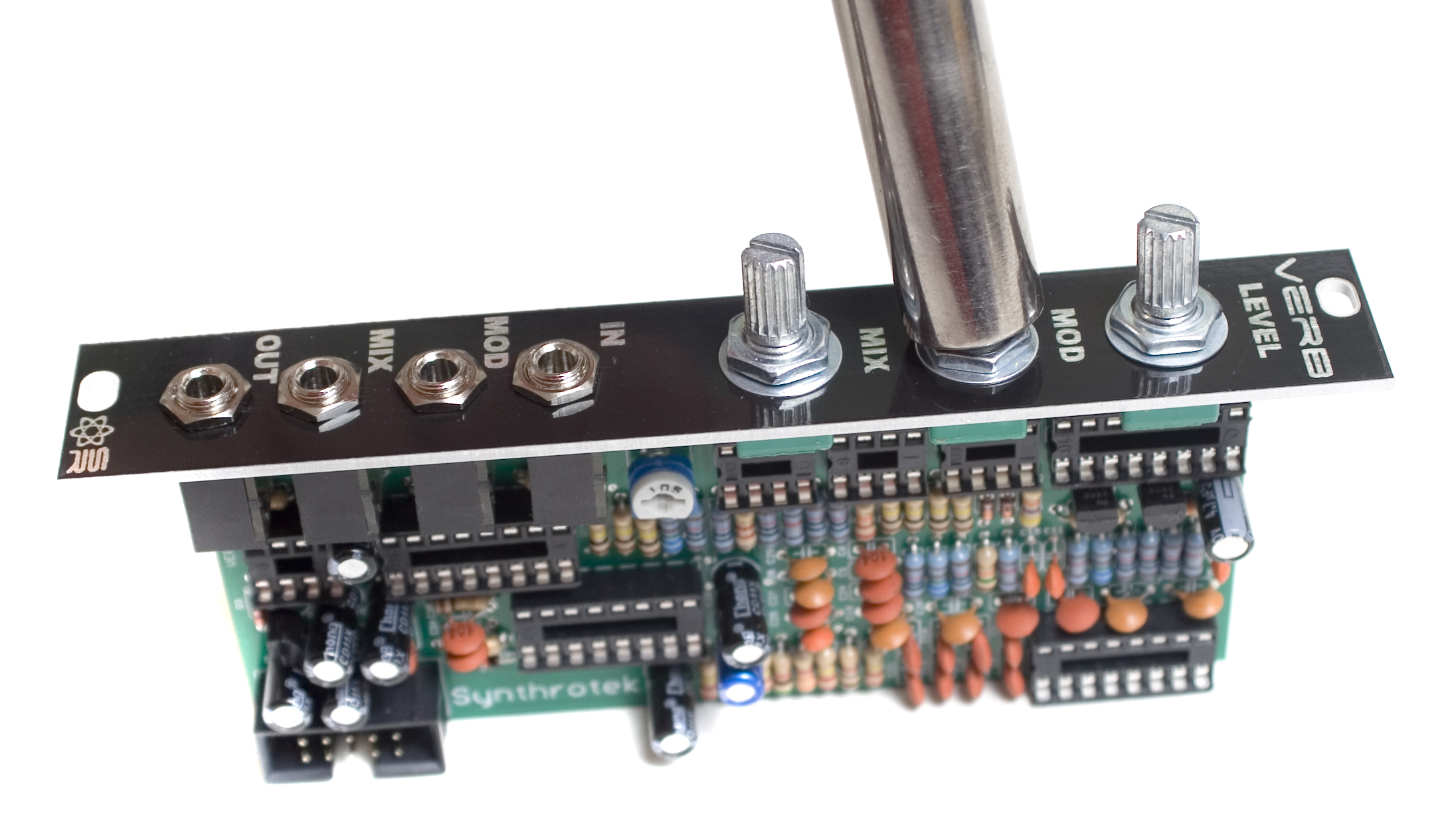
Now grab your trusty socket and tighten the nuts down (Don’t over tighten!) and Insert the ICs into their sockets.
When inserting the ICs, make sure to align the notch in the end of the IC (or the dot, in the case of the 8 pin ICs) with the notch that is both on the socket and the PCB.
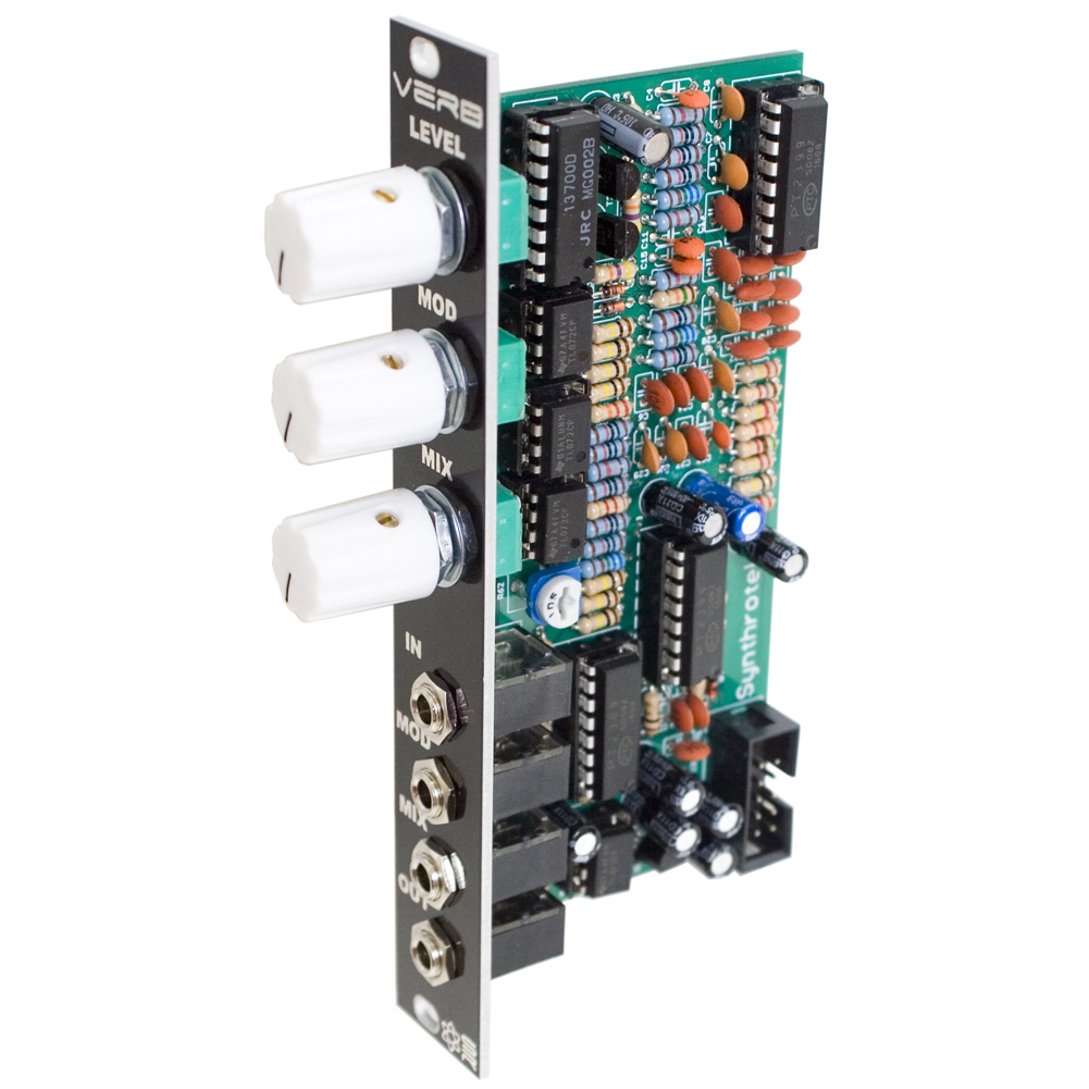
Completed Unit
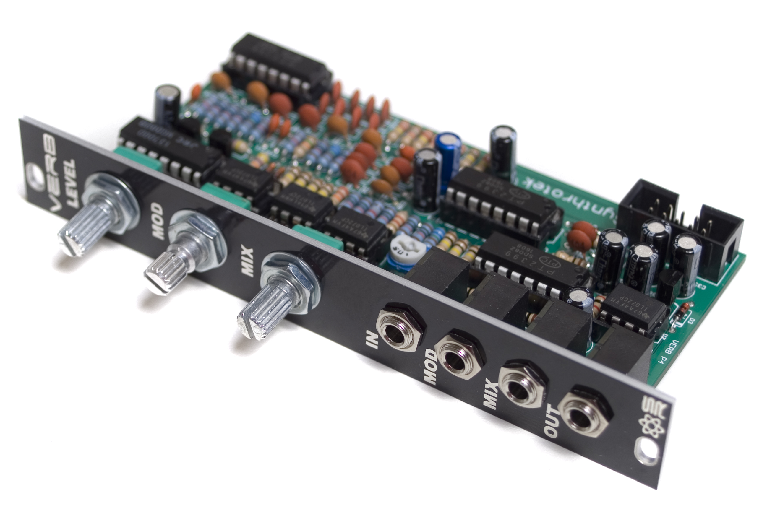 Congratulations! You’ve just completed building the Synthrotek Verb!
If you have any troubles with your build, check out our Troubleshooting Guide, or shoot an email to store@synthrotek.com
Calibration Instructions
Welcome to the calibration instructions for the Synthrotek Verb! These instructions assume you have a completed, fully functioning module.
On the Verb, there is only one calibration point, the trimmer potentiometer at R62. This trimmer controls the gain on the input stage.
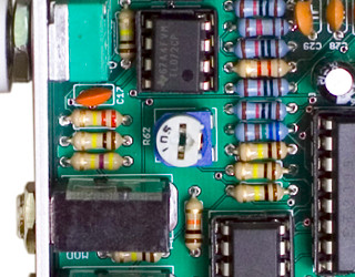
Turning this trimmer CW will decrease the gain (lowering the level), and turning it CCW will increase the gain (raising the level).
To calibrate your Verb, we recommend the following patch:
- VCO patched into a VCA (triangle wave is best for hearing audible differences)
- Relatively slow gate patched into an envelope
- Envelope on linear taper
- Output of Envelope patched into CV control of VCA.
- Output of VCA patched into the Verb
- Output of Verb patched into an output module of some sort.
Basically, you want a short-ish ‘pulse’ going through your Verb so that you can clearly hear the reverb effect.
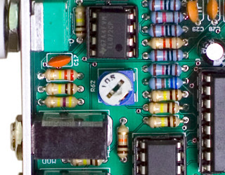
Once everything is set up, Turn your MIX knob and Level Knob to 3 o’clock position. Then adjust the trimmer CW to adjust the Verb until you are satisfied with the output. Because everyone’s tastes are different, there isn’t one ‘right’ position for the trimmer, but we’ve found adjusting it to the position shown below sounds pretty good.
If you have any further questions or concerns, feel free to shoot us an email at store@synthrotek.com
Calibrating With an Oscilloscope
Calibrating a Verb with an oscilloscope is very similar to how it is described above, with a few minor changes.
Instead of using a triangle wave, it’s best to use a square wave, as they are easier to see on a scope.
Make sure to run both the dry and wet signals through a buffer before plugging them into the scope.
Turn the Mod and Mix knobs all the way CCW, and the Level knob all the way CW.
You should be able to see something like the picture below on your scope.
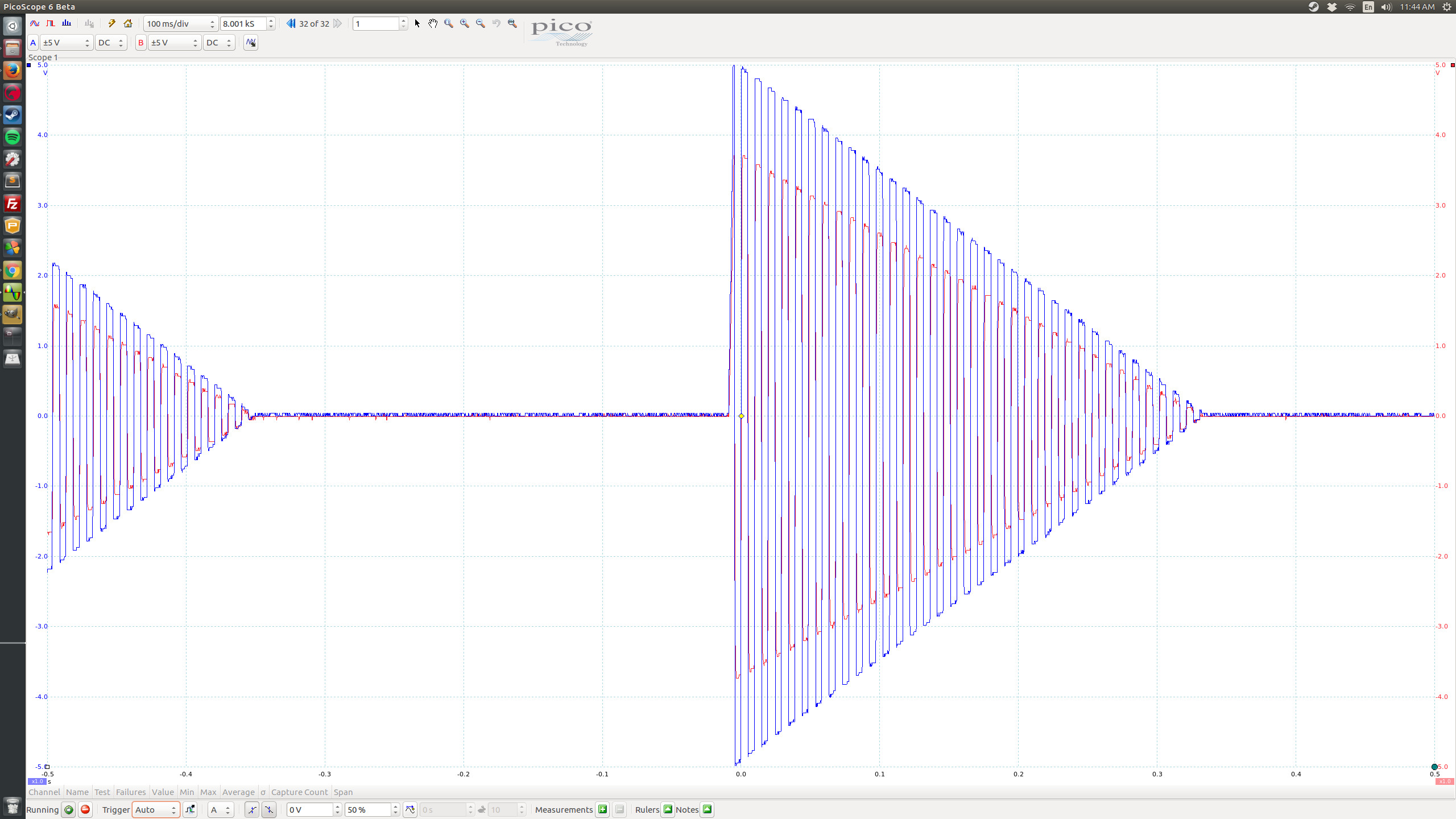
In the picture above, the Blue signal is the dry square wave, and the Red signal is the output of the Verb.
If your wet signal is a lower level than the dry signal, turn the trimmer CCW until they match.
If your we signal is hotter than the dry signal, instead turn the trimmer CW until they match.
You should now see something like the picture below on your scope.
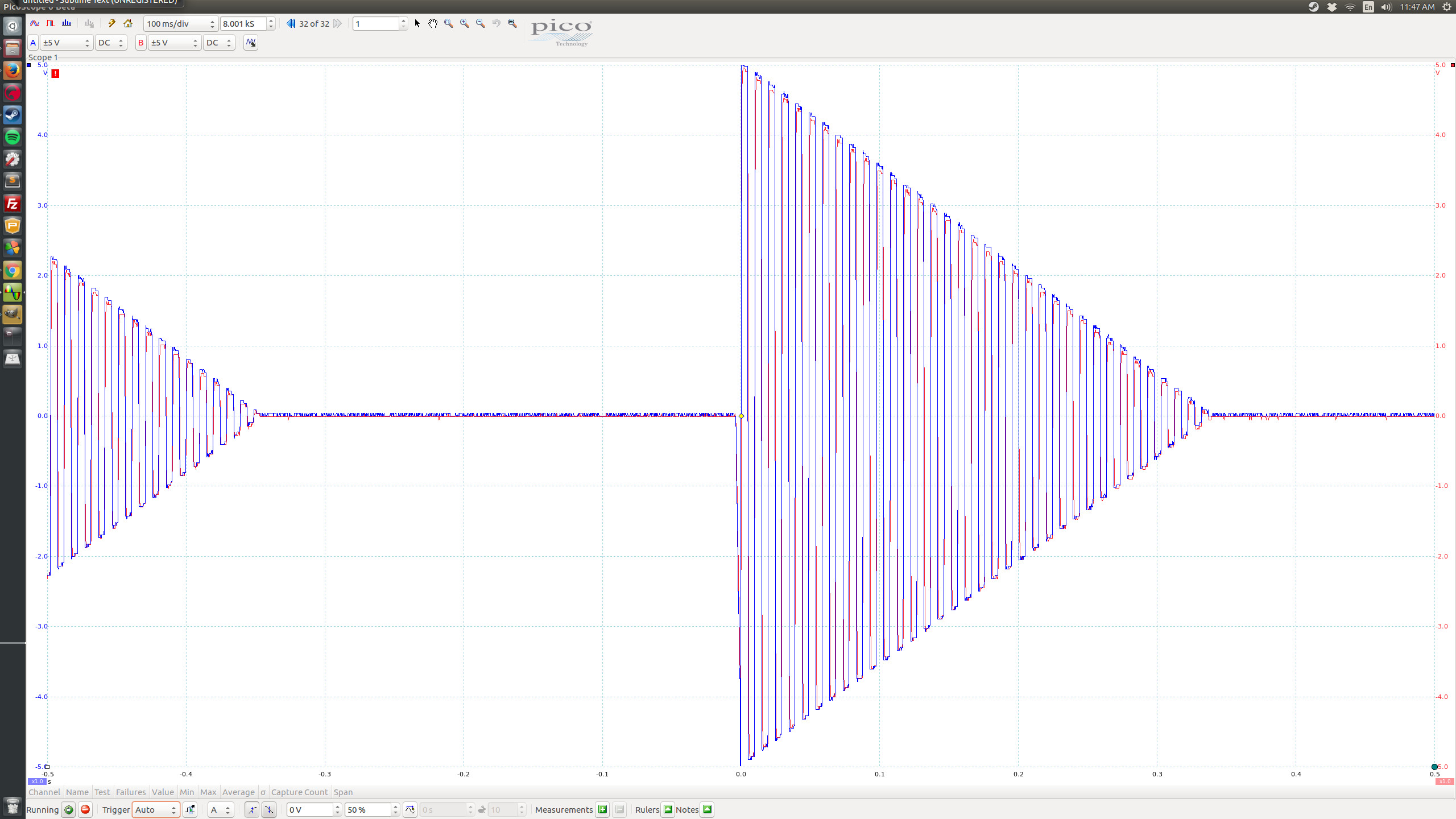
If you have any further questions, feel free to contact us at store@synthrotek.com