


Important Links
Product Page
Store Page
Assembly Instructions
Bill of Materials
Capacitor and Resistor Lookup Guide
MST ’07 Buffered Multiple Assembly Instructions
NOTE: You will need a micro Phillips screwdriver to assemble this product.
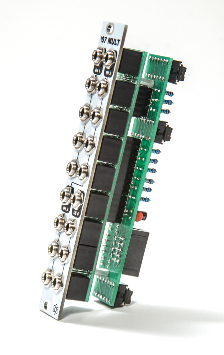
MST ’07 Buffered Multiple Assembly Instructions
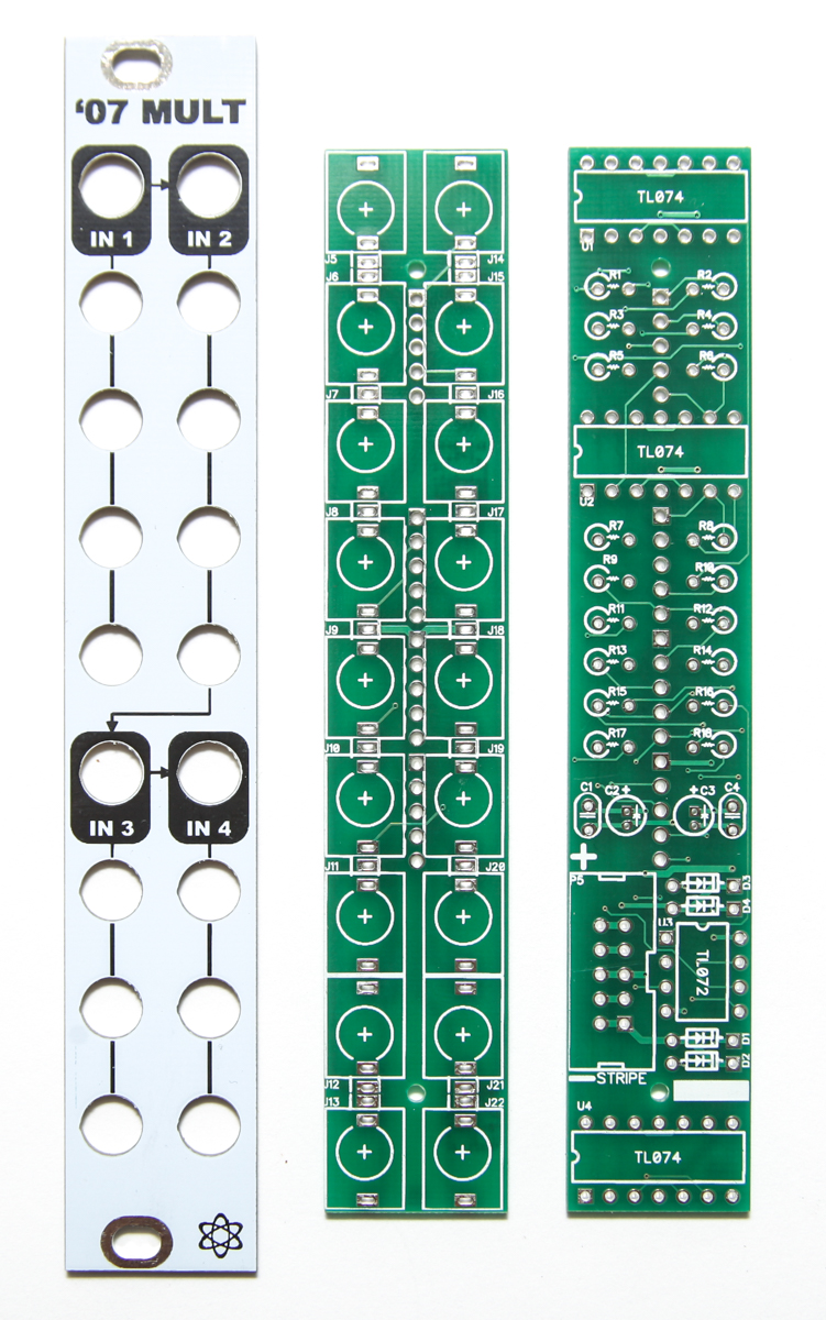
4HP ’07 Buffered Multiple PCB Panel
If you have a different version, please click HERE for instructions.
Thank you for purchasing the MST ’07 Buffered Multiple Eurorack module kit! This is an intermediate build. There are some stand-up resistors and a lot of components crowded together. If you feel like you can handle it please proceed! If not, get some help from a friend with experience or purchase a fully completed unit.
ATTN: Please follow the BOM and these instructions and don’t populate from the PCB alone. Also sometimes we cannot get the exact pictured components, so please look over your parts and check the codes first. Lets begin!
MAIN BOARD
Diodes
Start with the diodes as shown below, then carefully flip over on a firm surface to solder, then clip your leads. Diodes are polarized components so you must match the black stripe on your diodes with the white stripe on the PCB silkscreen.
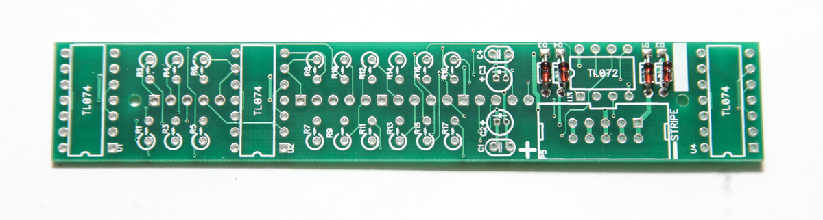
4HP ’07 Buffered Multiple DIODES
Capacitors
The ceramic capacitors are not polarized, so it doesn’t matter which way you orient them when populating. Insert them into their appropriate spots as per the BOM, and then flip your project over on a flat, hard surface and solder them in place, clipping the excess leads. Next up are the electrolytic capacitors. These are polarized, so pay close attention to how they are oriented on the PCB. Insert the longer of the two legs into the solder pad that is closest to the ‘+’ symbol on the PCB. The stripe on the capacitor should be facing AWAY from the ‘+’ symbol. Once these guys are in, flip your project over, solder, and clip any excess leads.
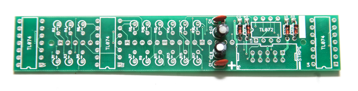
4HP ’07 Buffered Multiple Capacitors
IC Sockets
Next up are the IC sockets. Pay close attention to the half moon looking notch in one side of the socket, and make sure it matches up with the same notch on the silkscreen. Once they are all populated, carefully flip your project over. A stiff card or another PCB could help with this process. Once you have it flipped over, start by soldering only one leg of each socket. Then check to make sure everything is flat and straight, then continue soldering the rest of the legs.

4HP Eurorack Buff Mult IC sockets
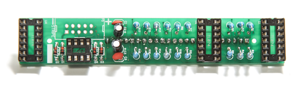
Male Header Pins
Add 5 and 15 pin male headers to the PCB as shown below and turn over carefully. Start by soldering only one leg of each header. Then check to make sure everything is flat and straight, then continue soldering the rest of the pins.
4HP Buffered Mult Male Header Pins
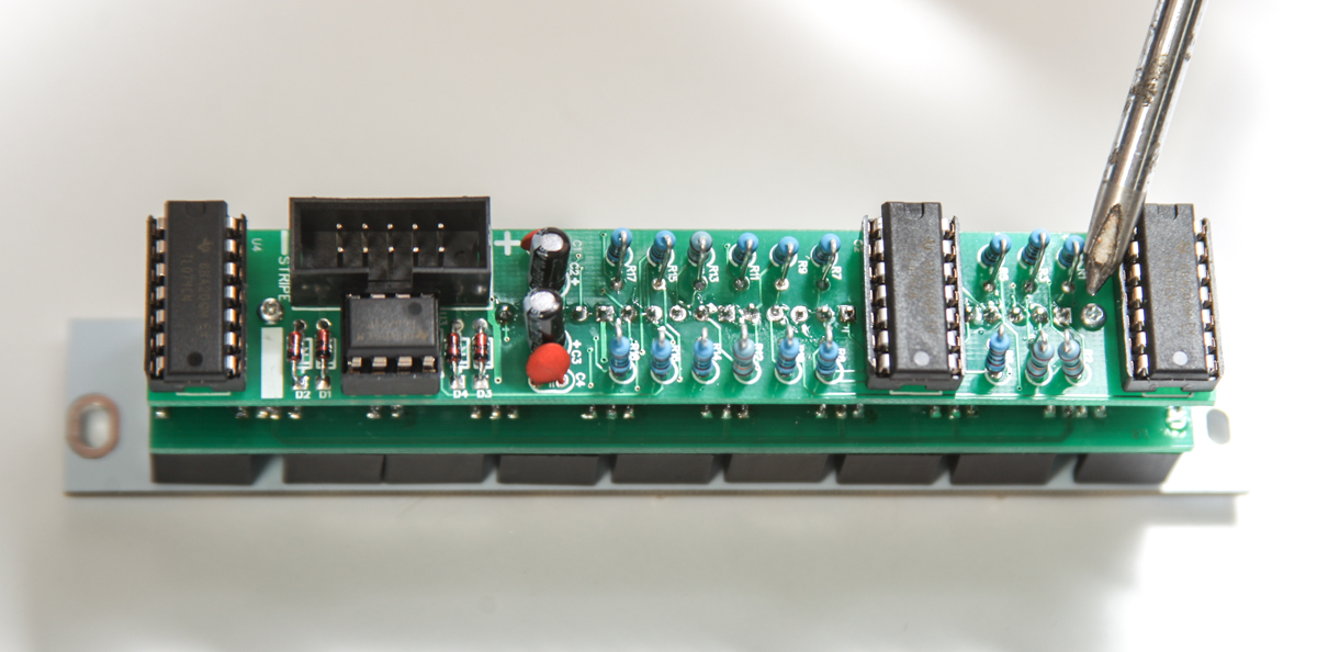
Resistors
Now we can populate the resistors. Insert each one into its appropriate spot, then carefully flip over your board, solder and clip the excess leads.
4HP Eurorack Buff Mult resistors
Power Header
Next, insert the 10 pin shrouded IDC header into the board, making sure to align the notch on the header, with the matching notch on the silkscreen. Then flip the board over, and solder into place. You can use a similar tactic with this header as with the IC sockets to get it flat.
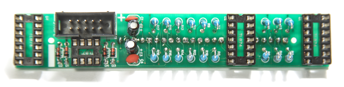
4HP Eurorack Buff Mult 10 Pin Power Header
ICs
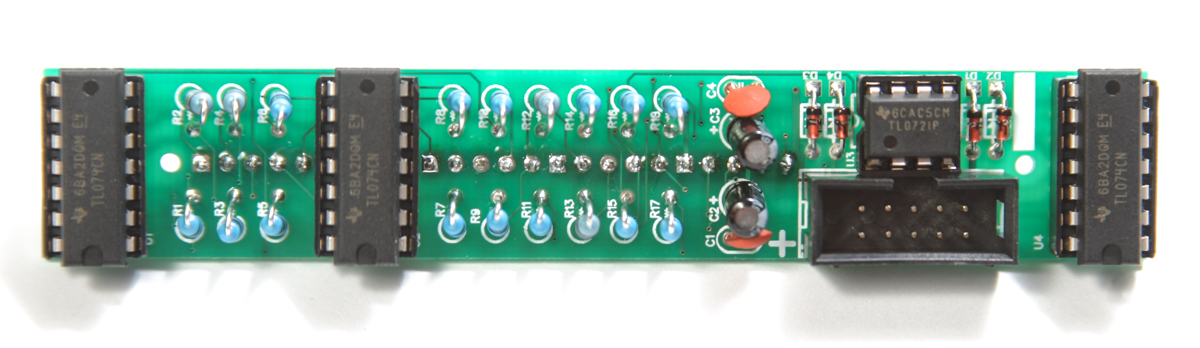
4HP Buffered Multiple ICs
Next, carefully insert the ICs into their proper sockets. You may need to slightly bend the legs of the IC inward so that it will fit. When inserting, make sure to align the notch in the IC with the same notch on both the socket and the board. Failure to properly align ICs may damage the IC or other components.
CONTROL BOARD
Let’s move over to the control board.
4HP Buff Mult Control Board
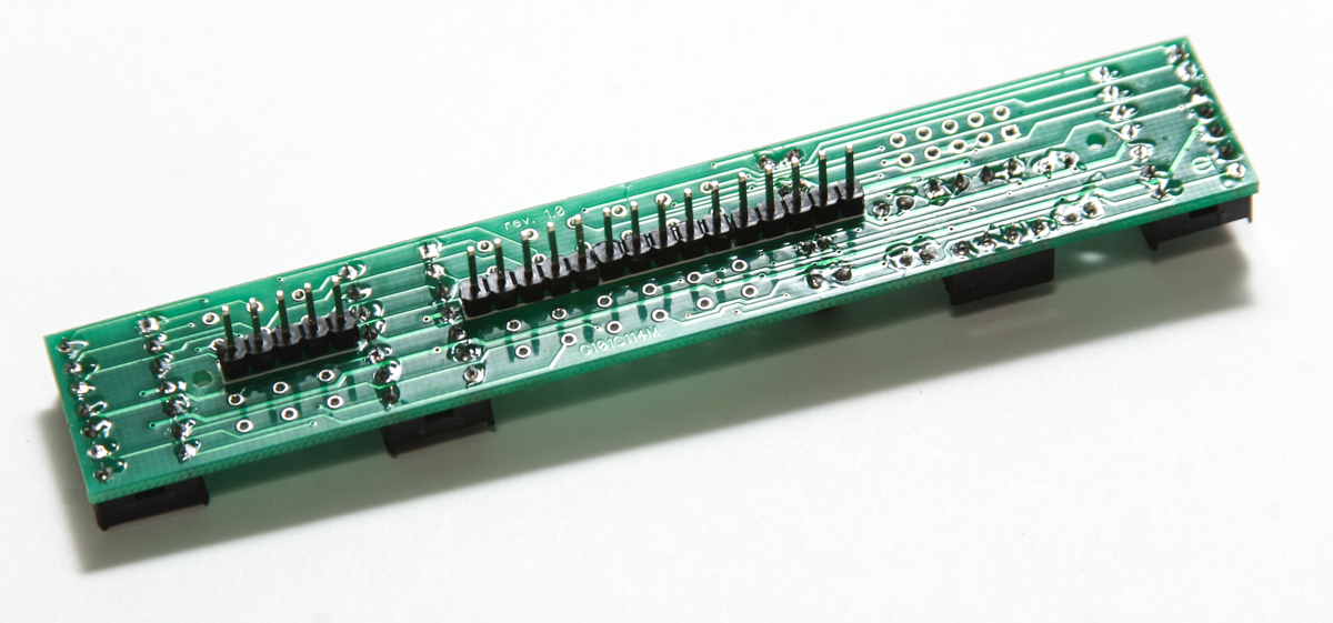
Female Headers/Sockets
Add 5 and 15 pin female headers to the PCB as shown below, turn over carefully and solder into place. Start by soldering only one leg of each socket. Then check to make sure everything is flat and straight, then continue soldering the rest of the pins.
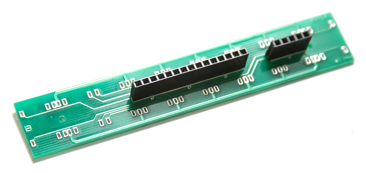
4HP Control Board Female Headers
Standoffs
Add the standoffs as shown below and use two of the small Phillips screws to screw it in place.
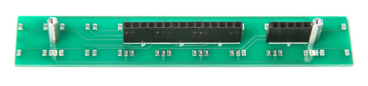
4HP Buffered Multiple Headers
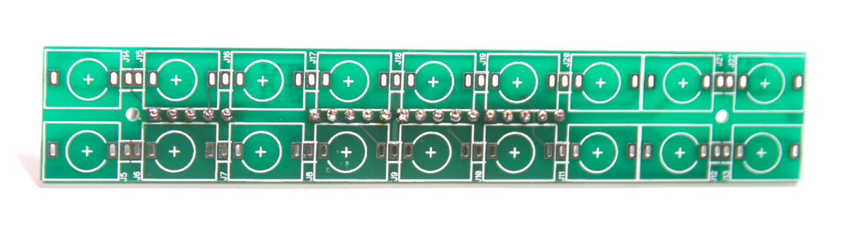
Jacks
Now you are ready to flip the project over, and start inserting jacks into the other side of the board. Insert all of the jacks as shown below, do not solder yet. Once you have the jacks in, place the front panel over the jacks, securing down with the supplied 3.5mm hex nuts. Be careful not to put the panel on upside down! The 5 pin socket on the control board should directly under inputs 1 and 2.
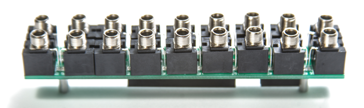
4HP Eurorack Buff Mult 3.5mm jacks
4HP Eurorack Buff Mult jacks and panel
4HP Eurorack Buff Mult jacks with nuts
Once the front panel is secured, flip the project over so it is resting on the jacks, and GENTLY push on the back so that the board is flat and straight.
When the panel and PCB are aligned and straight, you can solder up all the jacks.
Board Connection
Carefully connect the main board and the control board as shown below
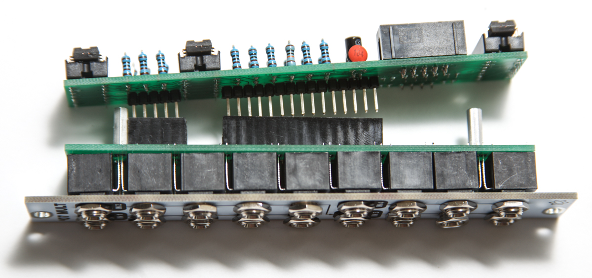
4HP Buffered Multiple Board to Board Connection
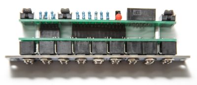
4HP Buffered Multiple Board to Board Connected
Take the remaining two screws and screw the two boards together
4HP Buffered Multiple Board to Board Final Screwing
Done
Congratulations! You’ve completed the MST ’07 Buffered Multiple!
Finished 4HP MST ’07 Eurorack Buffered Multiple
TESTING PROCEDURE
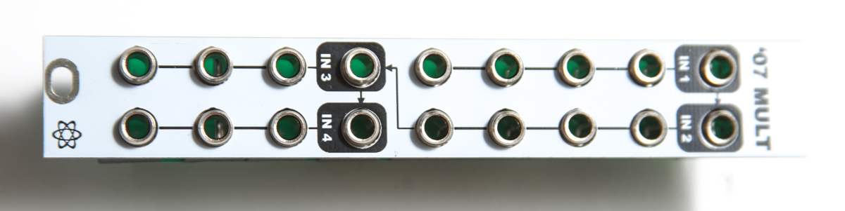
1 INPUT -> 14 OUTPUTS
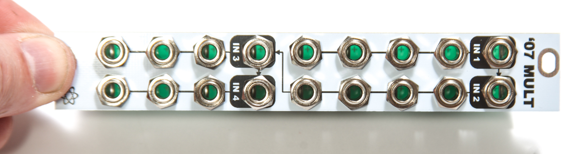
Start by plugging in a CV signal from a sequencer or a MIDI to CV module into INPUT A (top left jack inside a white box). Since INPUT 1 (top left jack inside a black box) is normalled to INPUT 2 (top right jack inside a black box), INPUT 2 normalled to INPUT 3 (bottom left jack inside a black box), and INPUT 3 is normalled to INPUT 4 (bottom right jack inside a black box) you can test all available 14 outputs.
TESTING WITH 1 OSCILLATOR
Plug a cable into a 1V/O INPUT on an Oscillator and plug the other end of the cable into Channel 1’s A Output jack on the MST ’07 Buffered Multiple. Make sure that each of the 4 “Channel 1” OUTPUTS, the 4 “Channel 2” OUTPUTS, the 3 “Channel 3” OUTPUTS, and the 3 “Channel 4” OUTPUTS are all making precise copies of the INPUT 1 signal by monitoring your Oscillator’s OUTPUT.
TESTING WITH MORE THAN 1 OSCILLATOR
Plug a cable into a 1V/O INPUT on Oscillator #1 and plug the other end of the cable into Channel 1’s A Output on the MST ’07 Buffered Multiple. Plug a cable into a 1V/O INPUT on Oscillator #2 and plug the other end of the cable into Channel 1’s B Output.
From here it’s best to get both Oscillators in tune with each other so you can hear them both reacting the same way to the INPUT 1 signal. Make sure that each of the 4 “Channel 1” OUTPUTS, the 4 “Channel 2” OUTPUTS, the 3 “Channel 3” OUTPUTS, and the 3 “Channel 4” OUTPUTS are all making precise copies of the INPUT 1 signal by monitoring the OUTPUTS from both Oscillators #1 and #2.
1 INPUT -> 4 OUTPUTS
1 INPUT -> 4 OUTPUTS
1 INPUT -> 3 OUTPUTS
1 INPUT -> 3 OUTPUTS
Keep the INPUT 1 signal plugged in from the previous test as we’ll break the INPUT normalling by plugging in a CV signal from another sequencer or a MIDI to CV module into INPUT 2. Plug in another CV signal into INPUT 3, and plug the last CV signal into INPUT 4.
Plug a cable into a 1V/O INPUT on Oscillator #1 and plug the other end of the cable into Channel 1’s A Output on the MST ’07 Buffered Multiple. Plug a cable into Oscillator 1’s FM / MOD input and plug the other end of the cable into Channel 2’s A Output. Plug a cable into a 1V/O INPUT on Oscillator #2 and plug the other end of the cable into Channel 3’s A Output. Plug a cable into Oscillator 2’s FM / MOD input and plug the other end of the cable into Channel 4’s A Output.
Make sure that each of the 4 “Channel 1” OUTPUTS, the 4 “Channel 2” OUTPUTS, the 3 “Channel 3” OUTPUTS, and the 3 “Channel 4” OUTPUTS are all making precise copies of their respective input signals by monitoring the OUTPUTS from both Oscillators #1 and #2.
By now you should be able to confirm that all INPUTS and OUTPUTS are working correctly on the MST ’07 Buffered Multiple and that your unit is working correctly.
If you have any questions or need help debugging, please first refer to our troubleshooting guide BY CLICKING HERE. If this gets you nowhere, please contact us by email for support. Thank you again for purchasing your kit from Synthrotek!
Great module. Easy assembly. Excellent instructions. Really useful module especially in a large system where the buffering helps distribute signals and voltages to a number of modules (especially VCOs which are prone to “sag” without buffering.
Thanks guys
Jon
@Jonathan Shapero
Rad, thanks Jonathan!
The screw holes in the pcbs I have are like 1.5mm I am confused?? 🙁
Hi Bart, the screws holes take 0-80 screws. They have to be pretty tiny to fit in between the jacks. You can skip the standoffs, they aren’t required.
If you ordered a kit and received the wrong type of standoff, let me know and I will send the correct type.