Thank you for purchasing the Synthrotek M/DIV CV Controlled Clock Multiplier and Clock Divider kit! This is an intermediate build. It is very important to get all the components properly soldered into the PCB in the correct placement. If you feel like you can handle it, please proceed! If not, get some help from a friend with experience or purchase a fully completed unit.
Please build according to the BOM, and not these instructions or the pictures alone. Some components may have changed since these were written, or we may not be able to get the exact looking components in the pictures.
Logic Board Diodes
The diodes are polarized, so make sure to populate them with the cathode stripe in the same direction as indicated by the silkscreen.
Once everything is in place, carefully flip your project over and solder the components in place. Clip any excess leads on the bottom of the board.
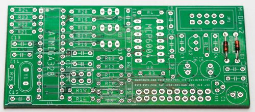
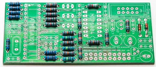
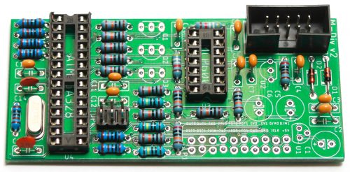
Resistors
Populate the resistors. Resistors are non-polarized, so it doesn’t matter which direction you put them on the PCB, but it will help with any troubleshooting that may arise if you line up all the tolerance bands (on 1% resistors, this is a brown band) on one side. This will make it easier to read the color codes on the resistors. Bend the legs of the resistor over, then place it on the board.
Once everything is in place, carefully flip your project over and solder the components in place. Clip any excess leads on the bottom of the board.
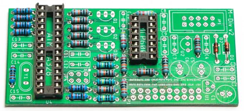
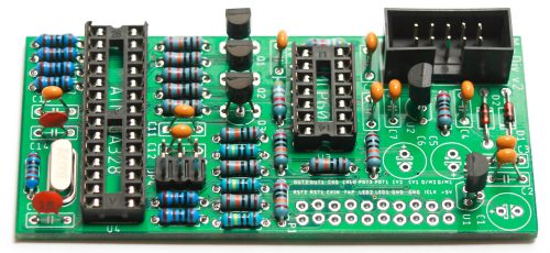
IC Sockets
Next up are the IC sockets. Take care when populating these to not bend any of the legs. Line up the notch at the end of the socket with the notch on the silkscreen. This notch indicates where pin 1 of the IC is. When you have them populated, carefully flip your project over and solder everything in place.
A trick to getting these nice and flat is to only solder one or two pins of each socket, and then reflow the solder joint while gently pushing on the top of the socket to seat it flat against the PCB. Then continue on and solder the rest of the pins.
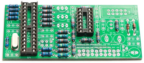
Crystal
Now place the crystal in place as show below. The crystal is not polarized. Carefully turn over, solder and clip leads.
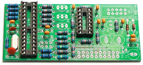
Ceramic Capacitors
Now we can populate the ceramic capacitors. These are non-polarized and can be inserted either direction. If the capacitor coating runs down the legs a little, make sure the coating doesn’t poke into the pads. Once they are in, carefully flip over your project and solder them in place, clipping the excess leads.
10-Pin Power Connector & Programming Header
The 2×3 programming header (JP4) is shown below, but it does not need to be populated because the IC comes pre-programmed.
Next up is the keyed shrouded power header. Make sure when populating this that the notch in the header is lined up with the notch designed on the silkscreen. Carefully turn over to solder.
Transistors and Voltage Regulator
Populate the transistors and voltage regulator by aligning the flat side of the component with the flat side of the silk screen. Turn over and carefully solder.
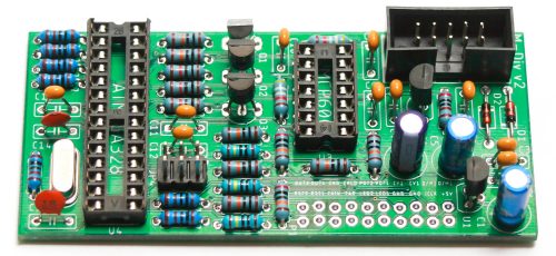
Electrolytic Capacitors
The electrolytic capacitors are polarized, so take care! Ensure that the longer leg (the leg that is further from the stripe indicator on the body) goes through the solder pad with the little ‘+’ symbol next to it.
Once it is aligned properly, carefully flip your project over and solder it in place, clipping the excess leads on the bottom.
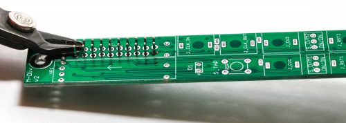
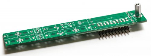
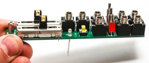
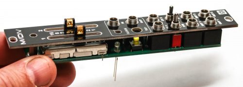
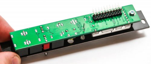
Control PCB Right Angle Headers
We are now going to start building the control board. We will start with the 2×10 right angle board to board header pins. Make sure when you populate these that the side of the header without the bend in it goes through the control board. The black plastic stopper should be resting against the board (see image below).
Make sure that you get these seated nice and flat against the board to ensure that everything will fit behind the front panel, and be at a nice 90 degree angle to the control board.
The pads of the header are slightly offset. This makes the header a little more difficult to insert, but it gives the boards a more secure connection.
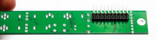
BEFORE YOU SOLDER VERY CAREFULLY clip the excess pin. Don’t clip them flush to the board; leave a little nub so that your soldering iron can make proper contact with the pin. Doing this allows the Slide Pots to fit on the board and makes for better soldering. Now you can carefully solder the pins.
After soldering, take a slide pot and set it in place in VR2 (don’t solder it in). If it sits flush on the board, the pins are low enough. If it doesn’t, clip any pins that are poking up too high. Remove the slide pot.
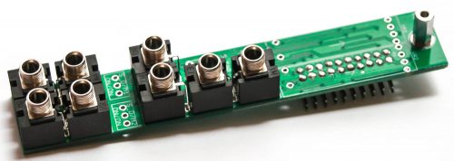
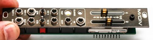
Standoff
Now take the standoff and place it into the board as shown below by securing it to the bottom of the control board with the silver colored Phillips screw.
Jacks
It can help to place the front panel over the jacks (and tighten some or all of the nuts) before you solder in order to align the jacks properly.
Next, carefully turn the board over to solder the jacks in place. Be mindful of keeping the jacks symmetrical (makes the project look better!).
LED & Switches
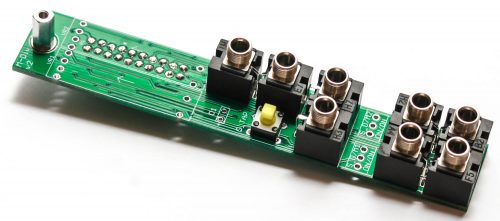
First, take the push button switch and place it in the project as shown above. Carefully turn over the project and solder in place.
Then take the LED and place it in the project as shown below. LEDs are polarized so make sure you place the LONG lead into the hole that is marked with a “+” next to it. Do not solder just yet.
Next place the two toggle switches into the PCB as shown below.
Now take the panel and place it over the project prior to soldering the LED and toggle switches.
Add a couple nuts to a couple jacks and secure the black hex screw into the standoff as shown below. You can now carefully turn over the project and solder the TOGGLE SWITCHES IN PLACE. Wait for the LED.
Push the LED into the panel as far as you like as shown below.
Now solder the LED legs on the rear of the project, clipping the leads.
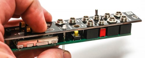
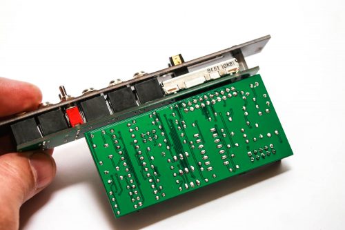
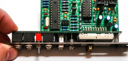
Final Board Mating
Now CAREFULLY marry the control and logic boards together as shown below.
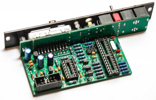
Solder one pin toward the middle, then check to make sure the logic board is 90 degrees to the control board. If it looks good, solder the rest of the connecting pins in place as shown below.
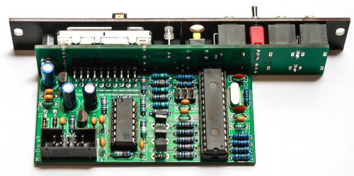
Integrated Circuits
Insert the ICs into their sockets. You will need to bend the legs inward a little to make them fit. Match up the notch on the ICs with the notch on the socket and PCB silkscreen. Make sure that all the legs are firmly seated in the socket.
Button Cap
Now take the push button cap and firmly press it onto the push button switch as shown below.
Programming
Plug in the module and hit the TAP button a couple times. You should see the LED sliders start to flash. Program the slider range by turning them all the way up and then power cycling the module while holding the TAP button.
You’re Done!
Way to go! You have finished the M/DIV build. Now it’s time to get to patching!