


Important Links
Product Page
Store Page
Assembly Instructions
Bill of Materials
Capacitor and Resistor Lookup Guide
Welcome to the assembly instructions for the Cosmic Echo Squared! The Cosmic Echo Squared is the same as our popular Cosmic Echo in the 1590B case, but reworked to fit a 1590DD case.
If you’ve received your parts and ready to build, the first thing you should do is to check to make sure you have all the parts. Check your kit against the Cosmic Echo BOM. If you’re missing anything we’ll send it to you free of charge.
Soldering the Components
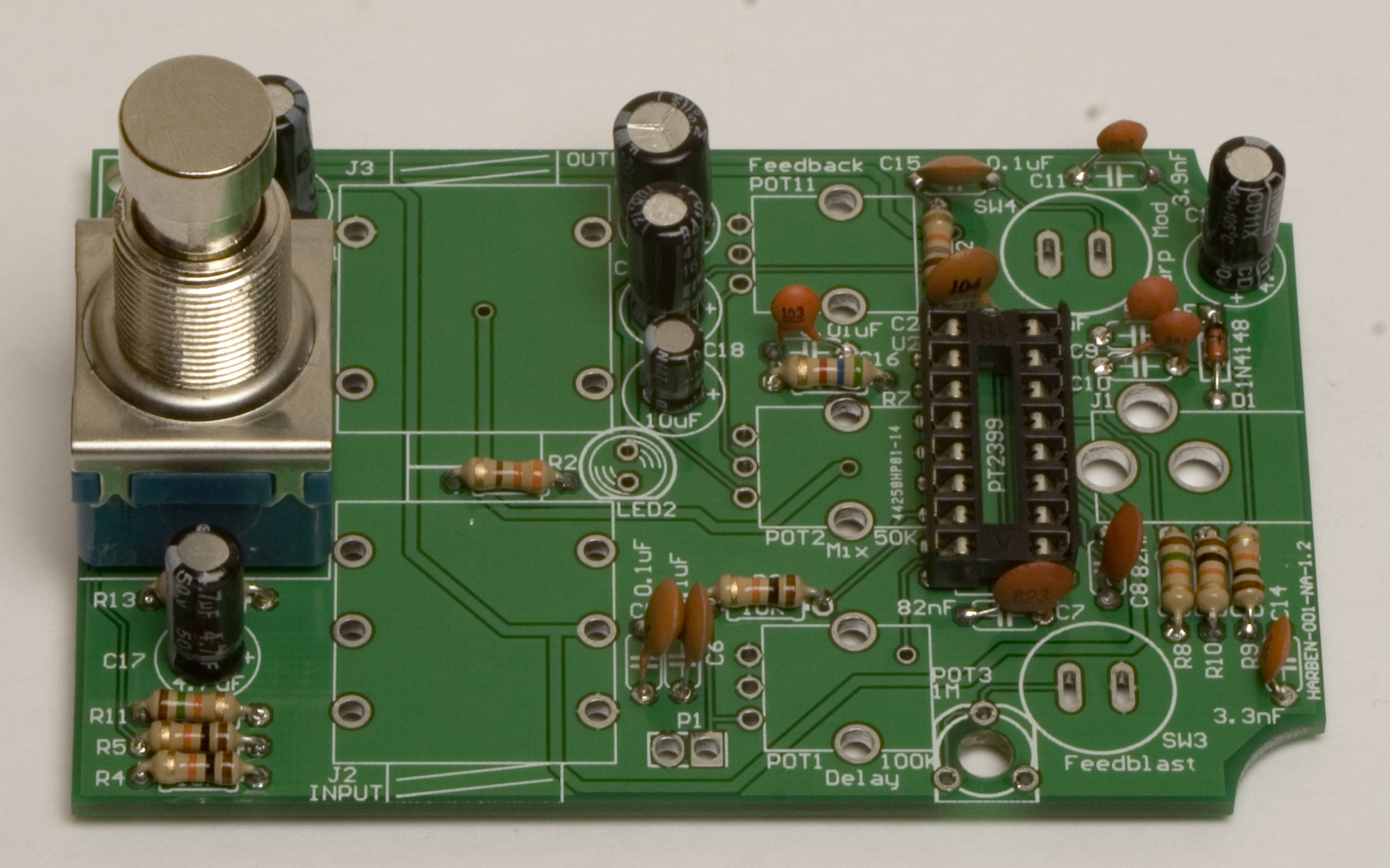
Attention: Changes may occur after the Assembly Instructions are created and the photos may not reflect those changes. Always use the BOM to verify the placement of components.
Optional Output Buffer Mod
We have designed an optional mod for the Cosmic Echo Squared, which is highly recommended. It is a JFET buffer for the output that reduces the volume drop of the circuit significantly. If you would like to do this mod, please scroll to the bottom of the page, and follow those instructions first.
Resistors and Diode
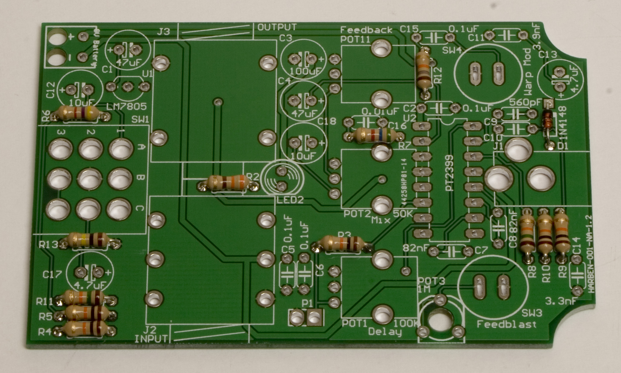
Cosmic Echo Squared Assembly Step 1: Soldering Resistors
First up, is getting the resistors soldered in, they are non-polar, so it doesn’t matter which way they go. The diode, however needs to be matched to the silkscreen on the PCB, with the stripe on the diode matching the stripe on the PCB.
IC Socket
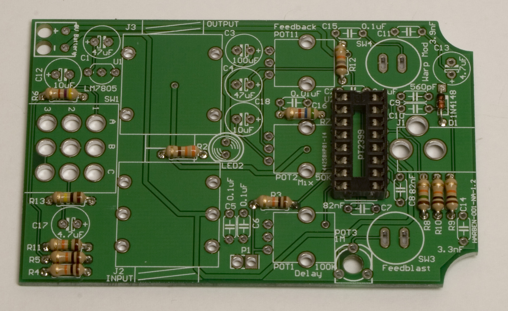
Cosmic Echo Squared Assembly Step 2: IC Socket
Next up, go ahead and solder the socket for the IC in place. Take care to match the notch on the socket with the notch on the PCB. A tip to getting the socket soldered flat is to only solder one or two pins on opposite corners first, then check the flatness, reheating while flattening if needed. Then go back and solder the rest of the pins, re-hitting the first two if needed.
Ceramic Capacitors
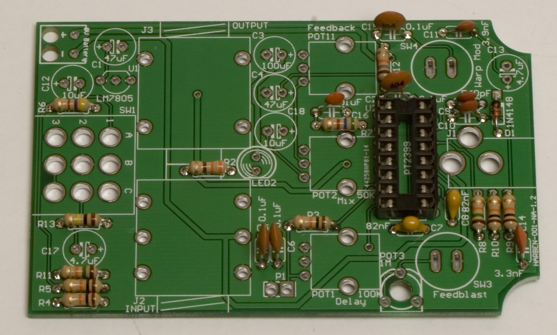
Cosmic Echo Squared Assembly Step 3: Ceramic Caps.
Now we can place in the ceramic capacitors, and solder them into place. They are non-polar like the resistors, so it does not matter which way you put them, but it is recommended to place them in a way that they will be easy to read later on, in case you need to troubleshoot your build.
Electrolytic Caps and Voltage Regulator
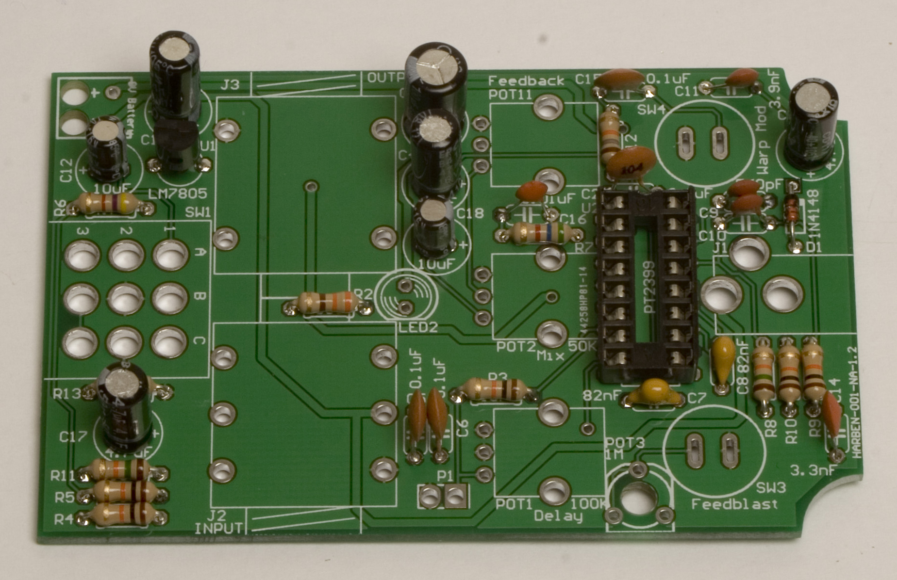
Cosmic Echo Squared Assembly Step 4: Electrolytic Capacitors
Now we can populate the electrolytic capacitors and the voltage regulator. Be careful when placing these, because they are polar, and need to be placed with the longer lead (anode) in the hole with the plus sign next to it. Likewise, the voltage regulator has a flat side on it that needs to be matched to the flat spot on the silkscreen printed on the PCB. If this is put in backwards, it could destroy a few other things on the circuit.
3PDT Stomp Switch
Cosmic Echo Squared Assembly Step 5: Stomp Switch
Next up is the 3PDT stomp switch. This needs to be placed with the flat side (either one) facing the front of the board, like in the picture. A tip to getting this guy in flat is to solder just the middle one, then while holding lightly, re-heat the solder and push into place. Once the solder is holding it flat, solder up the other 8 pins, and finally re-heat the first one to ensure a good electrical connection.
Potentiometer Prep
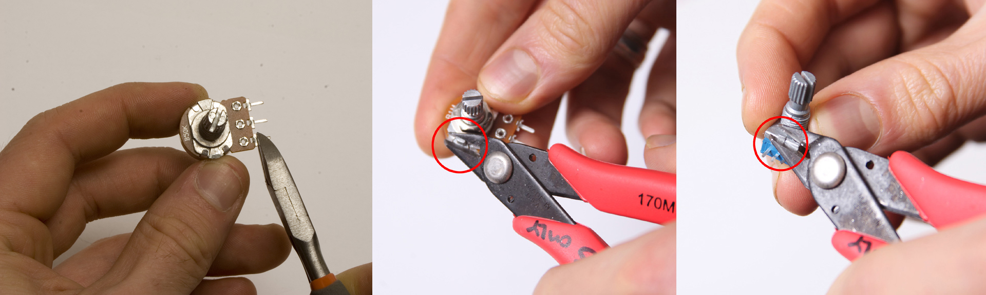
Remember to cut pins and nibs where needed.
The solder lug potentiometers that came with your kit may have come with PCB pins attached, or with nibs near the base of the shaft. It is easier to solder them without the pins, only using the holes. The nibs need to be clipped off in order for the potentiometer to sit flush against the case later. Make sure you check all of them.
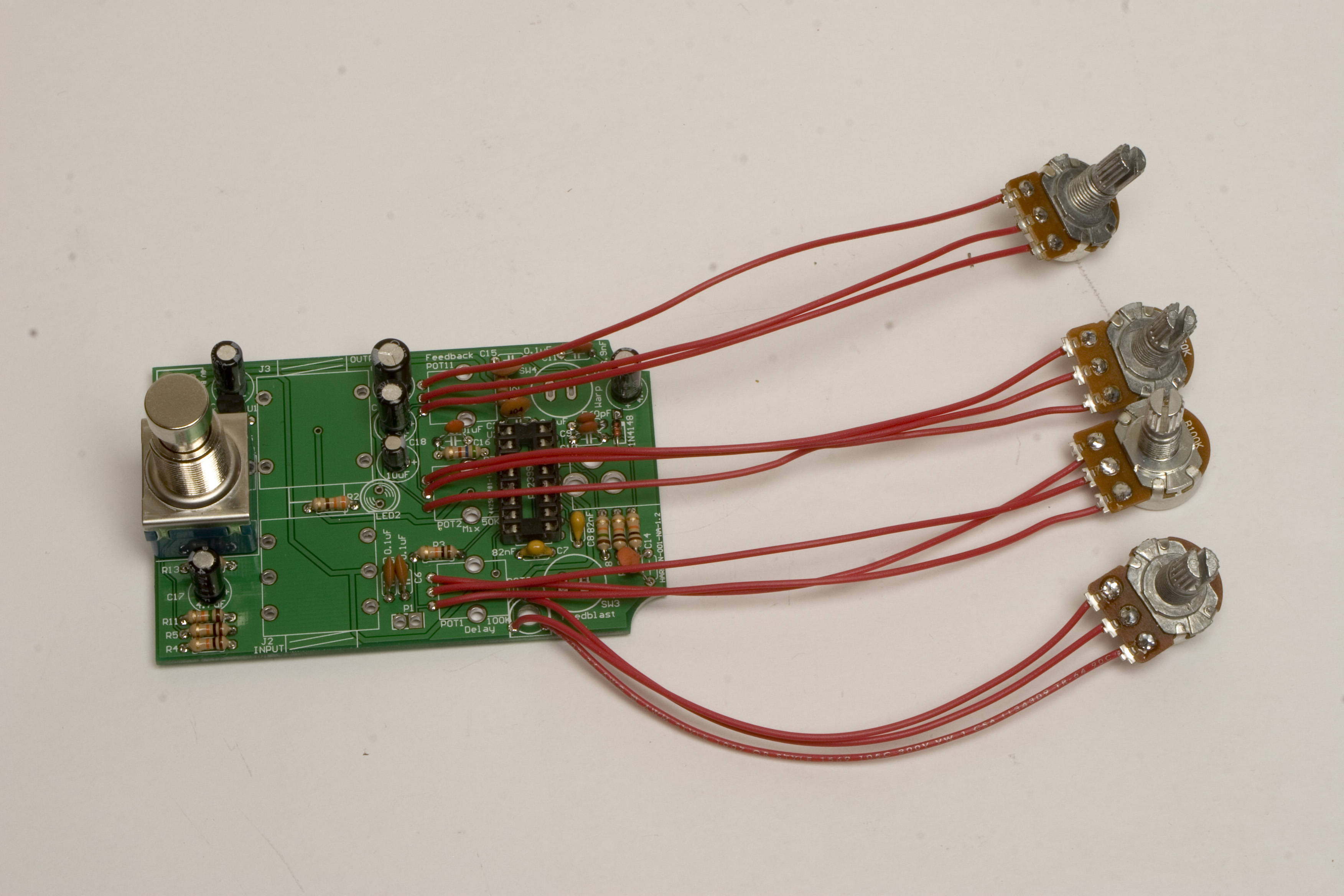
Solder Wires to All Components
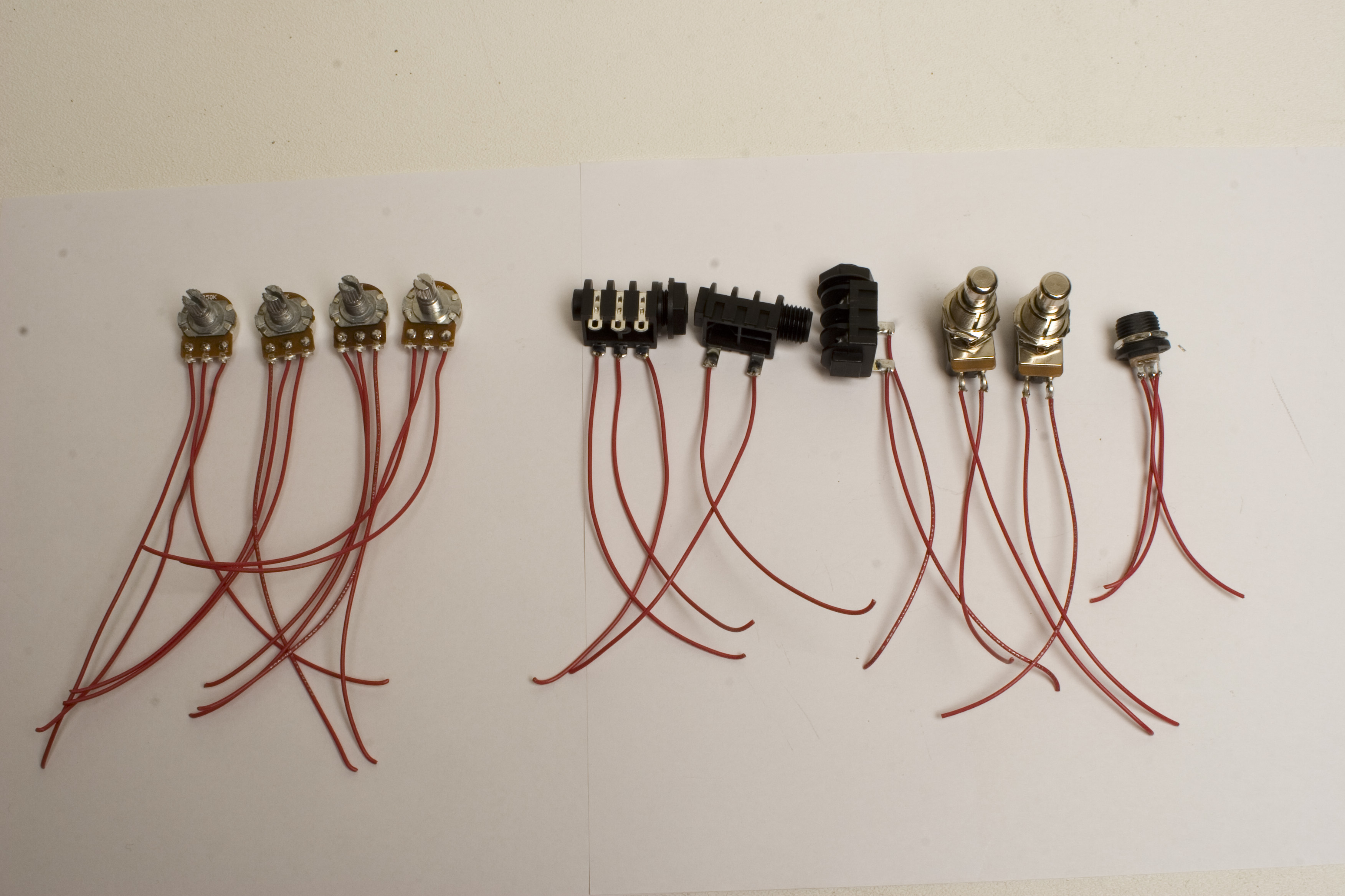
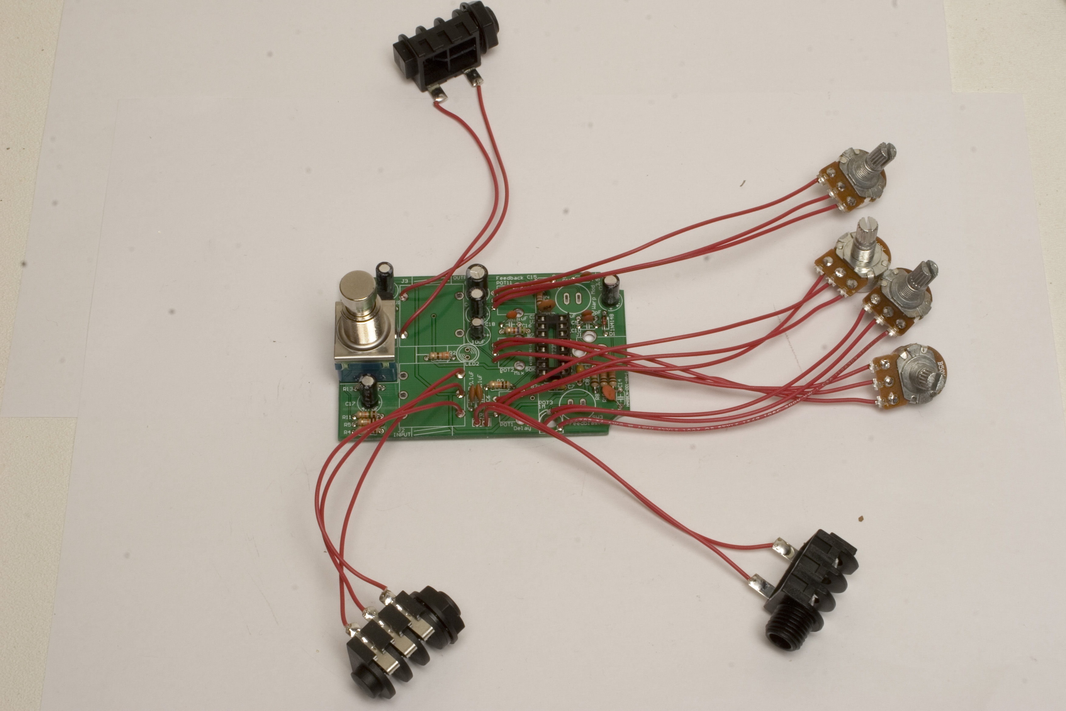
Cosmic Echo Squared Assembly Step 6: Solder wires to components.
It is easier to solder wires to the individual components, then solder the wires to the board, rather than the other way round. You will need 26 lengths of wire total for this project.
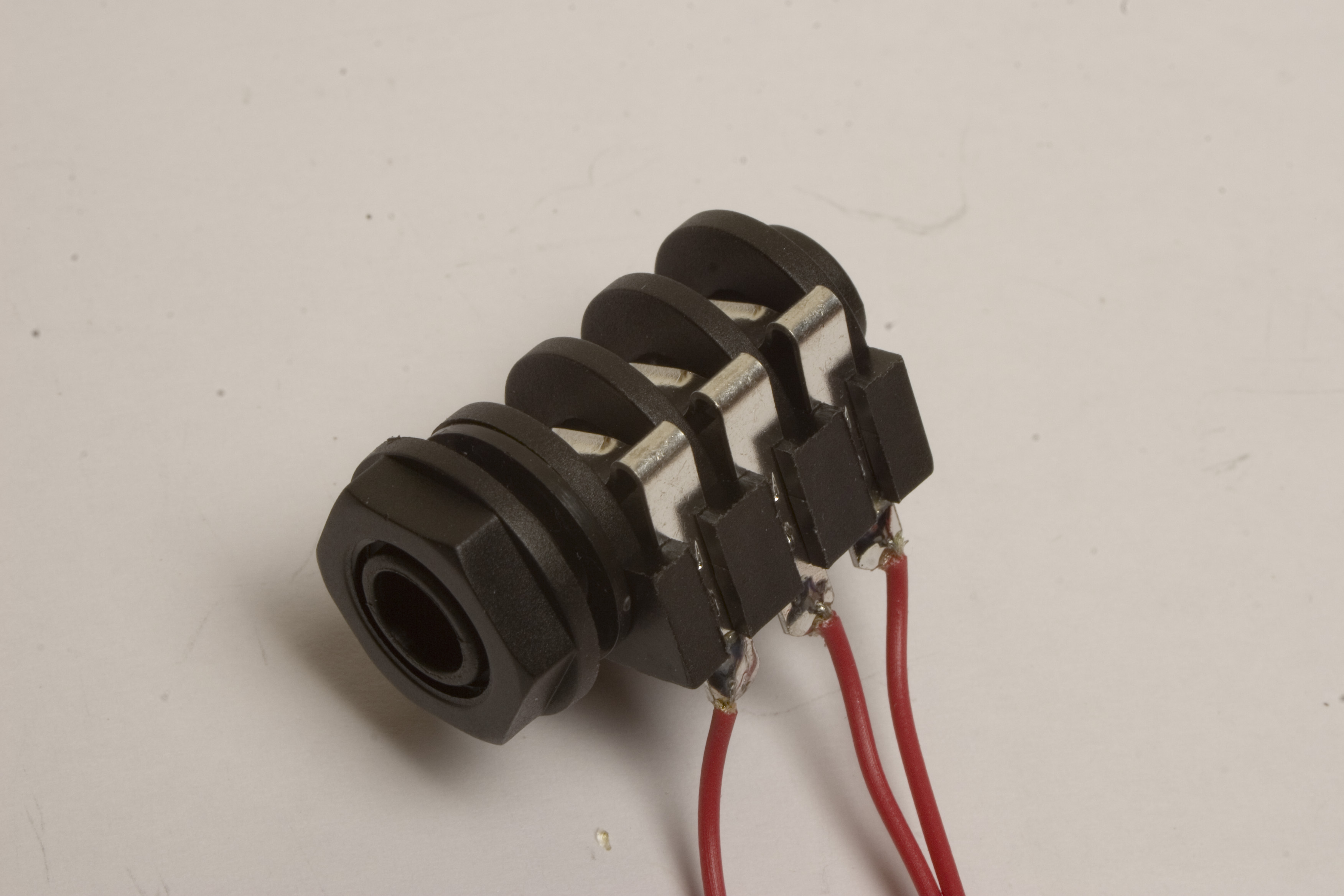
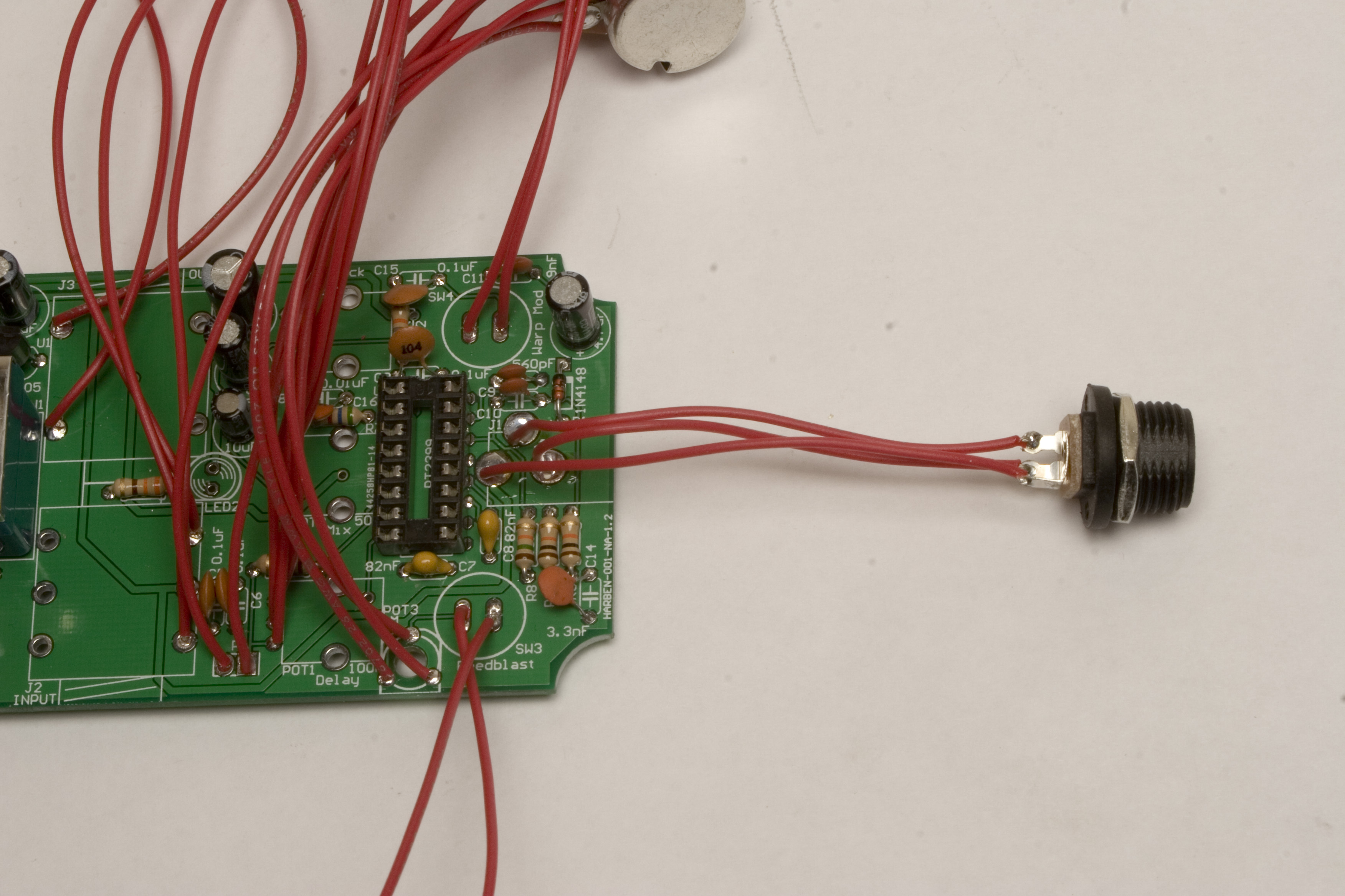
when soldering the stereo jack, make sure to solder your wires to the solder lugs on the side with the hump in the tabs, not the other side. If you did not receive the black plastic style jacks, and instead received the metal switchcraft jacks, please follow the wiring diagram below:
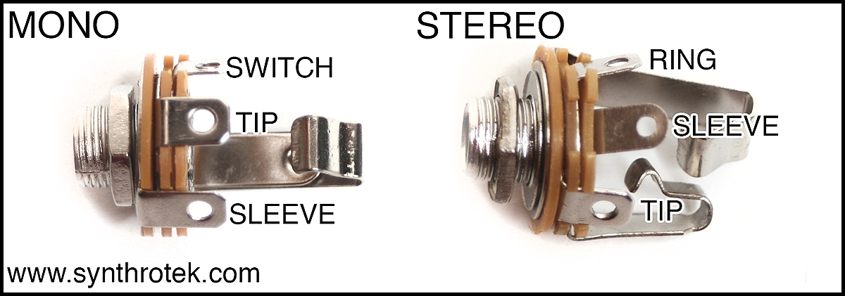
1/4″ Metal Audio Jack Wiring
Potentiometers
Cosmic Echo Squared Assembly Step 7: Soldering the pots in.
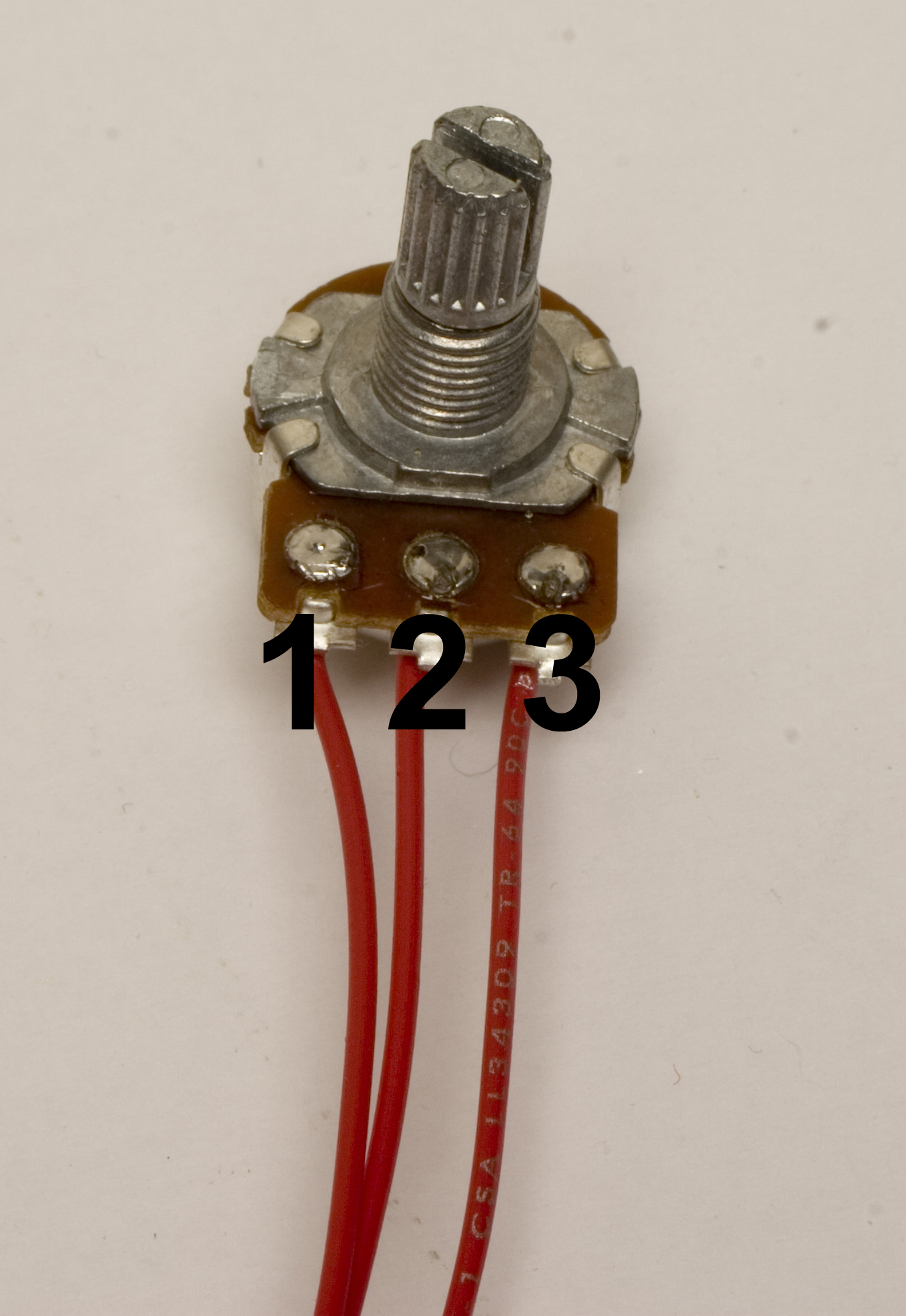
The first wired component to be soldered in is the potentiometers. Solder them into the three small holes at the designated area on the PCB. See the diagram below for proper pin numbering so your pots turn the right direction.
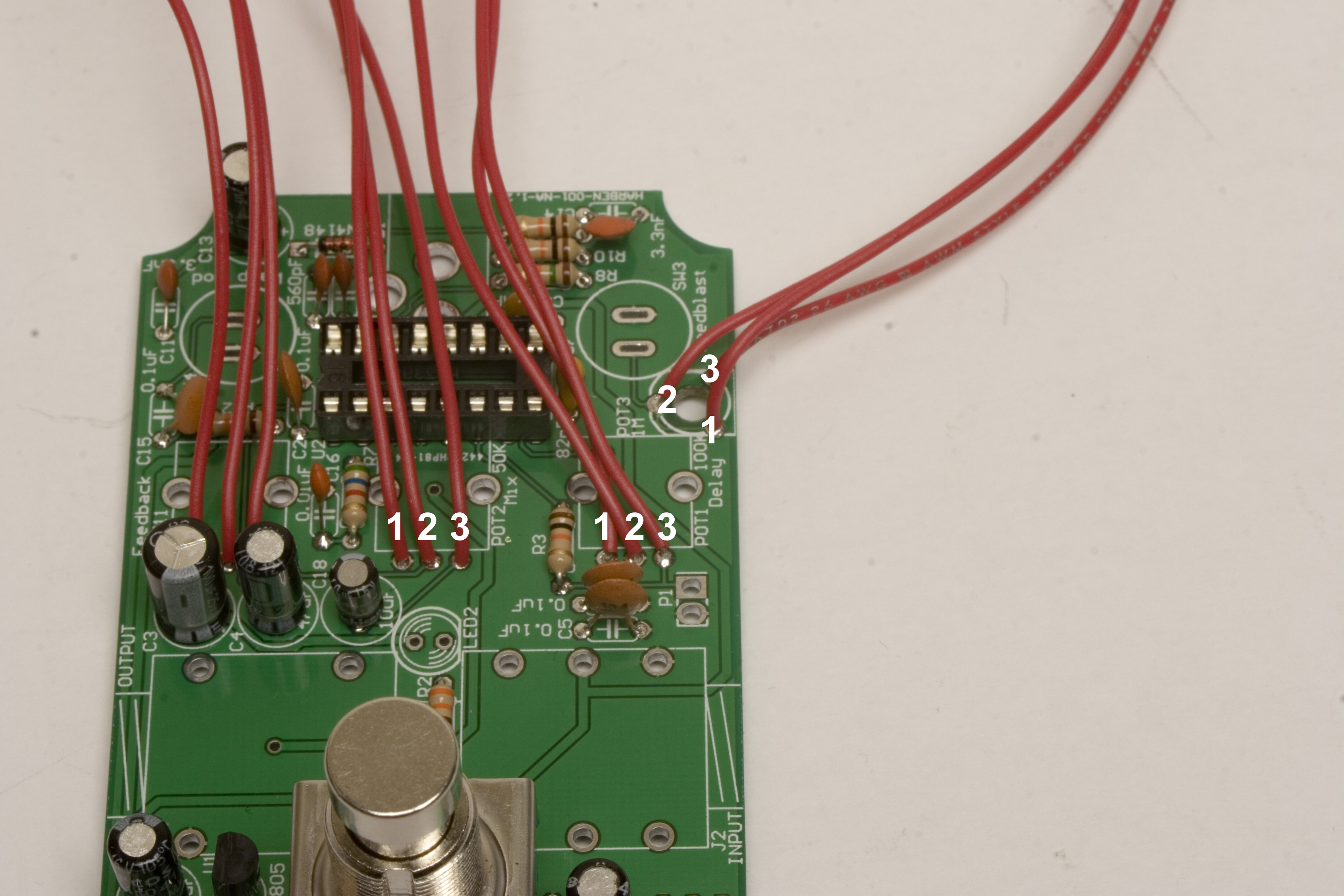
Match the numbering here to the numbering in the picture to the right.
Audio and Expression Pedal Jacks
Cosmic Echo Assembly Step 8: 1/4″ Jacks
Next up is the jacks for the Input, Output, and Expression pedal. Please see the diagram below for proper placement of the jack wires, as there are multiple vias, and only a couple are the right ones.
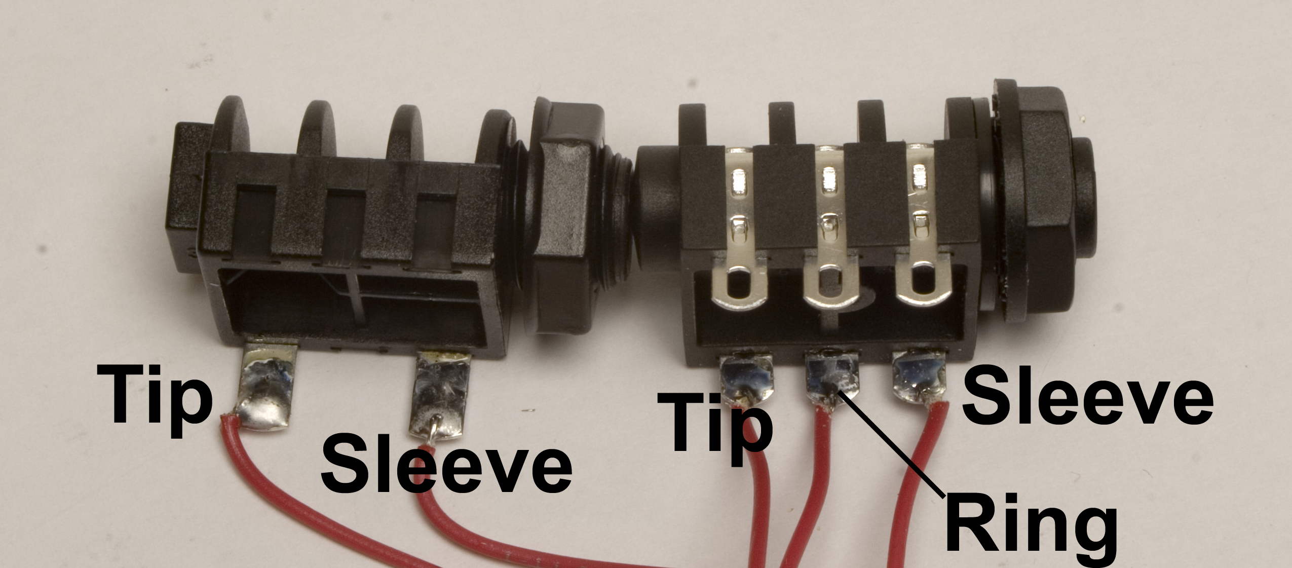
If you received metal jacks instead of the black plastic ones shown above, please use the diagram below for proper wiring.
1/4″ Metal Audio Jack Wiring
Match The Tip and Sleeve of the mono jack to the shown vias on the PCB. Your circuit will not work if not wired to these jacks. Likewise with the Stereo jack, match the Tip, Ring and Sleeve wires to the corresponding jacks on the PCB. For the expression pedal, the Tip gets wired to the square via, and the sleeve to the round one. These vias are marked P1 on the PCB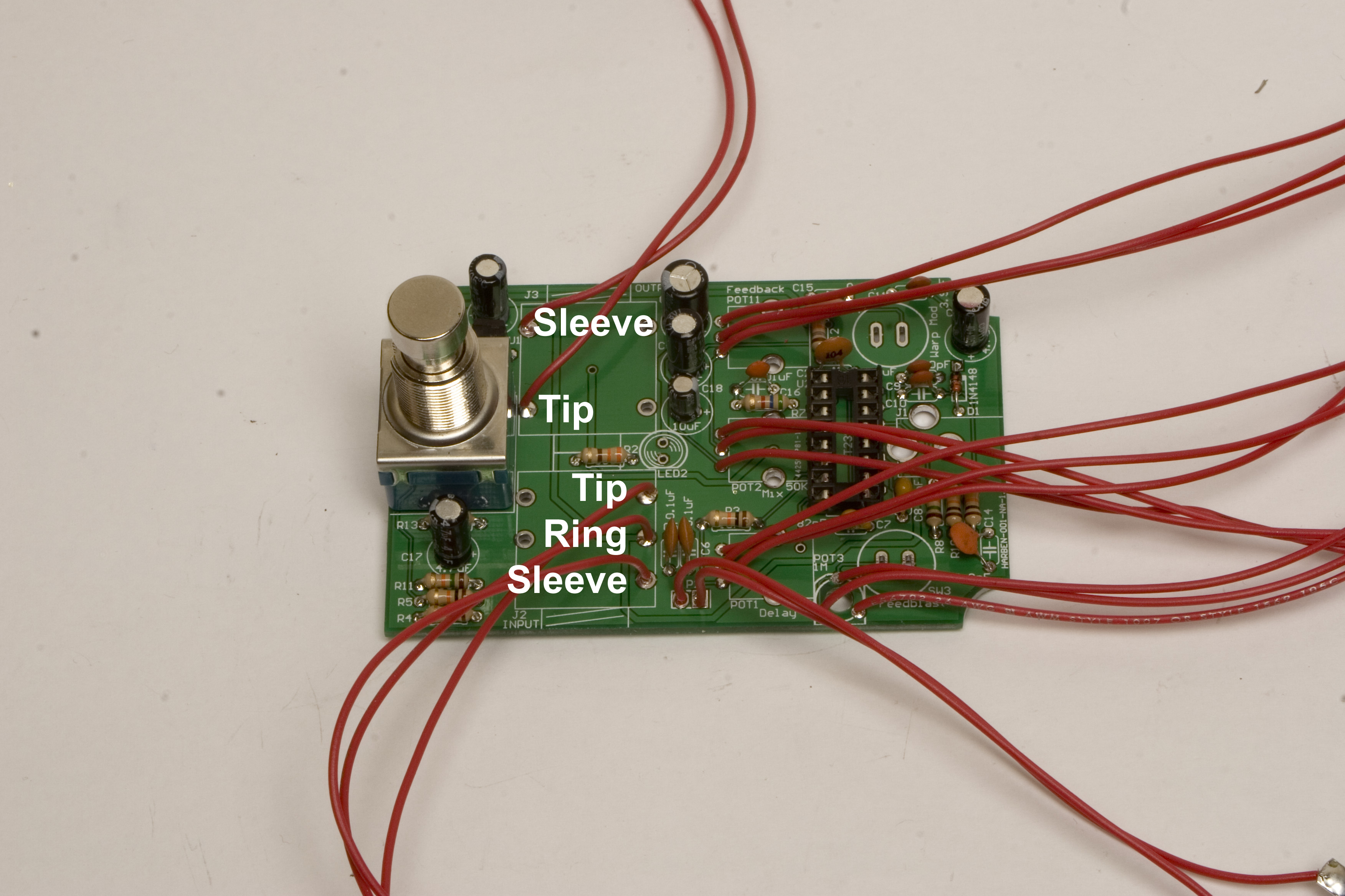
Momentary Switches
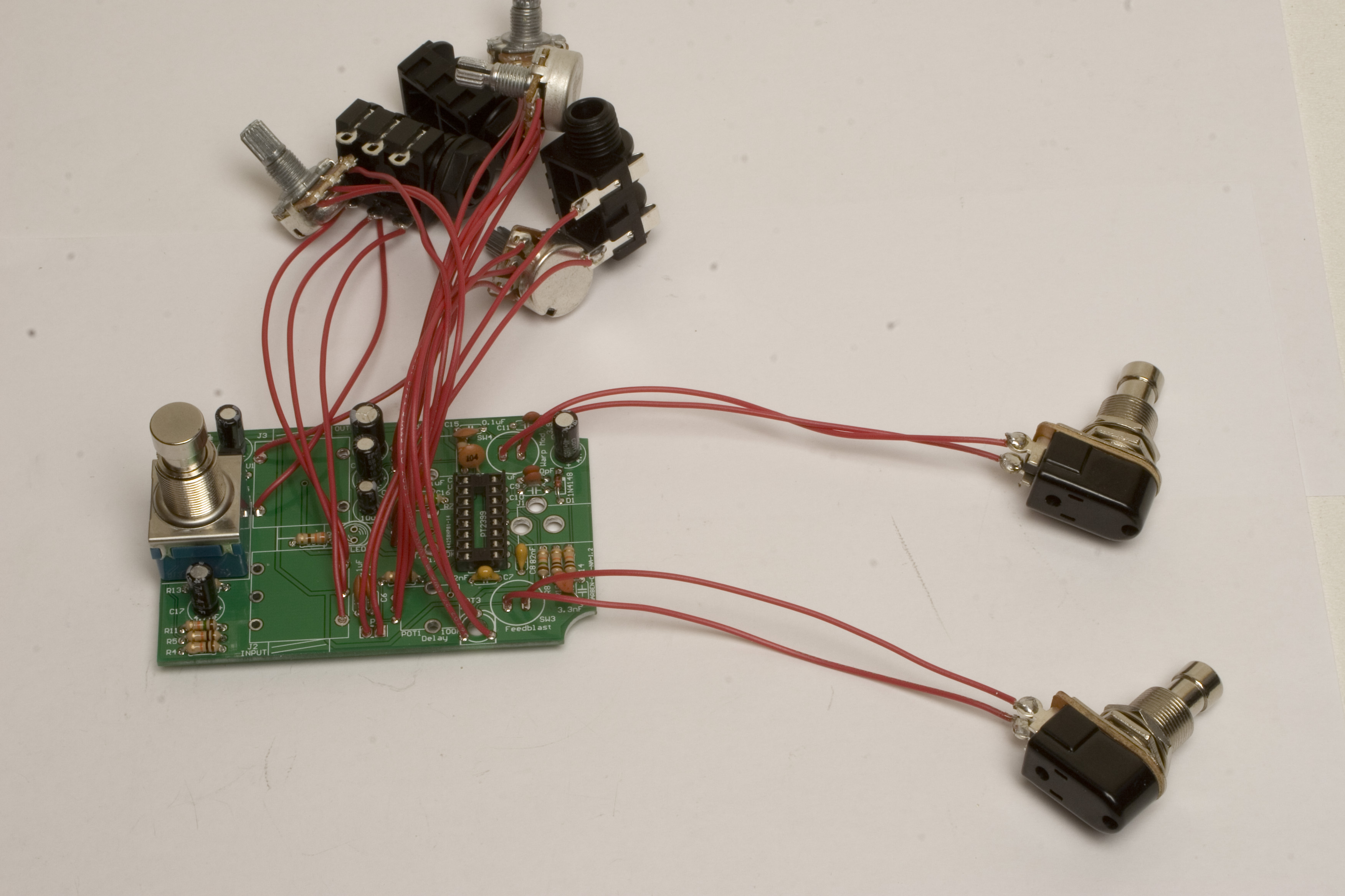
Cosmic Echo Squared Assembly Step 9: Momentary Stomp Switches
Next up are the momentary stomp switches. These are SPST switches, so it does not matter which wire goes to which via.
DC Jack
Cosmic Echo Assembly Step 10: DC Jack
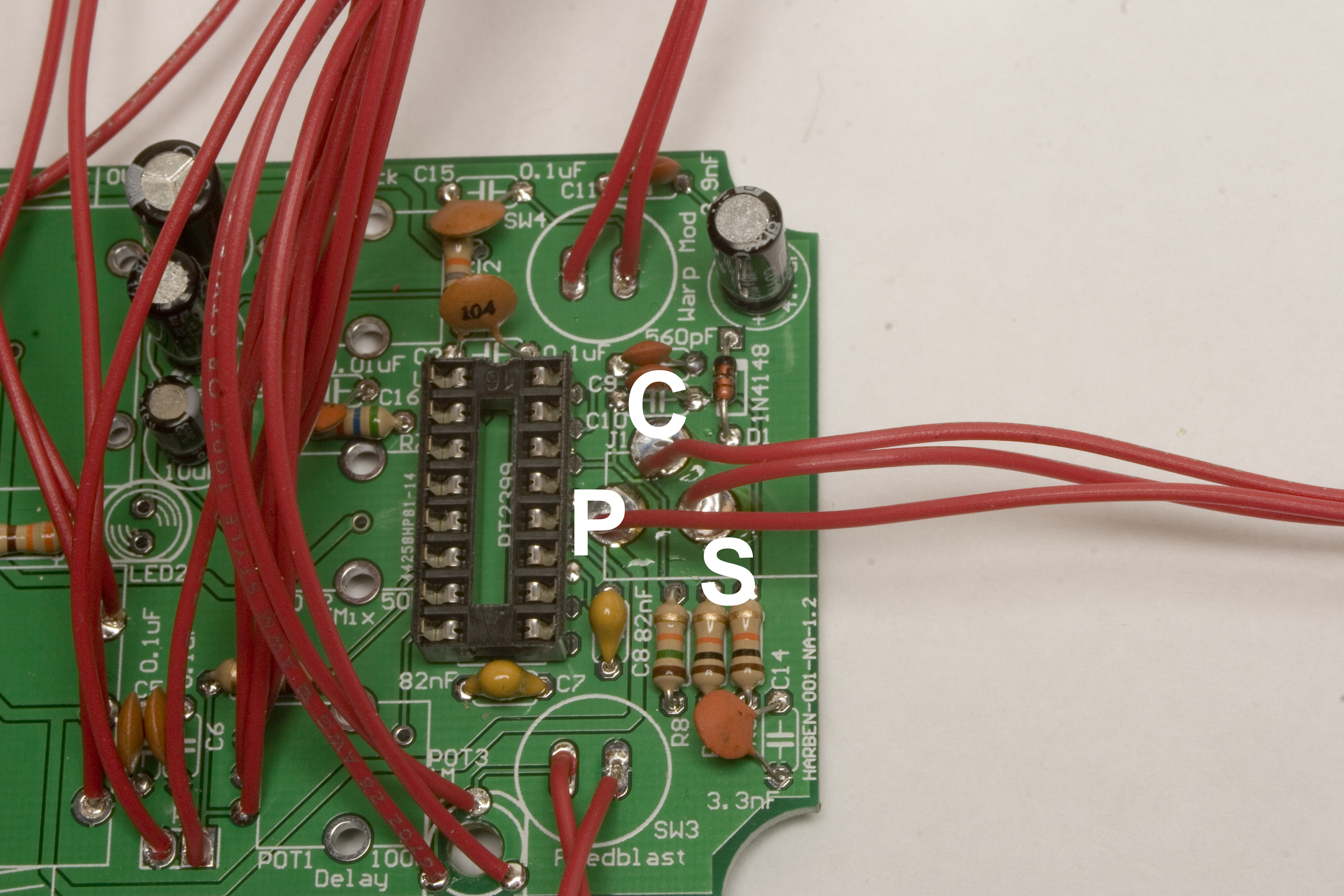
Now we can solder the DC jack into place. Please take a look at the following diagrams for placement of wires.
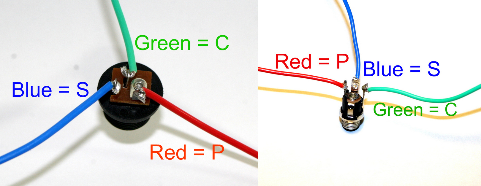
Depending on which DC jack you have, you may need to wire it differently. If you are sourcing your own, make sure it is a switched jack, and the center (-) pin goes to the spot labeled P, the sleeve (+) goes to C, and the switched pin goes to S.
9v Battery Clip and LED
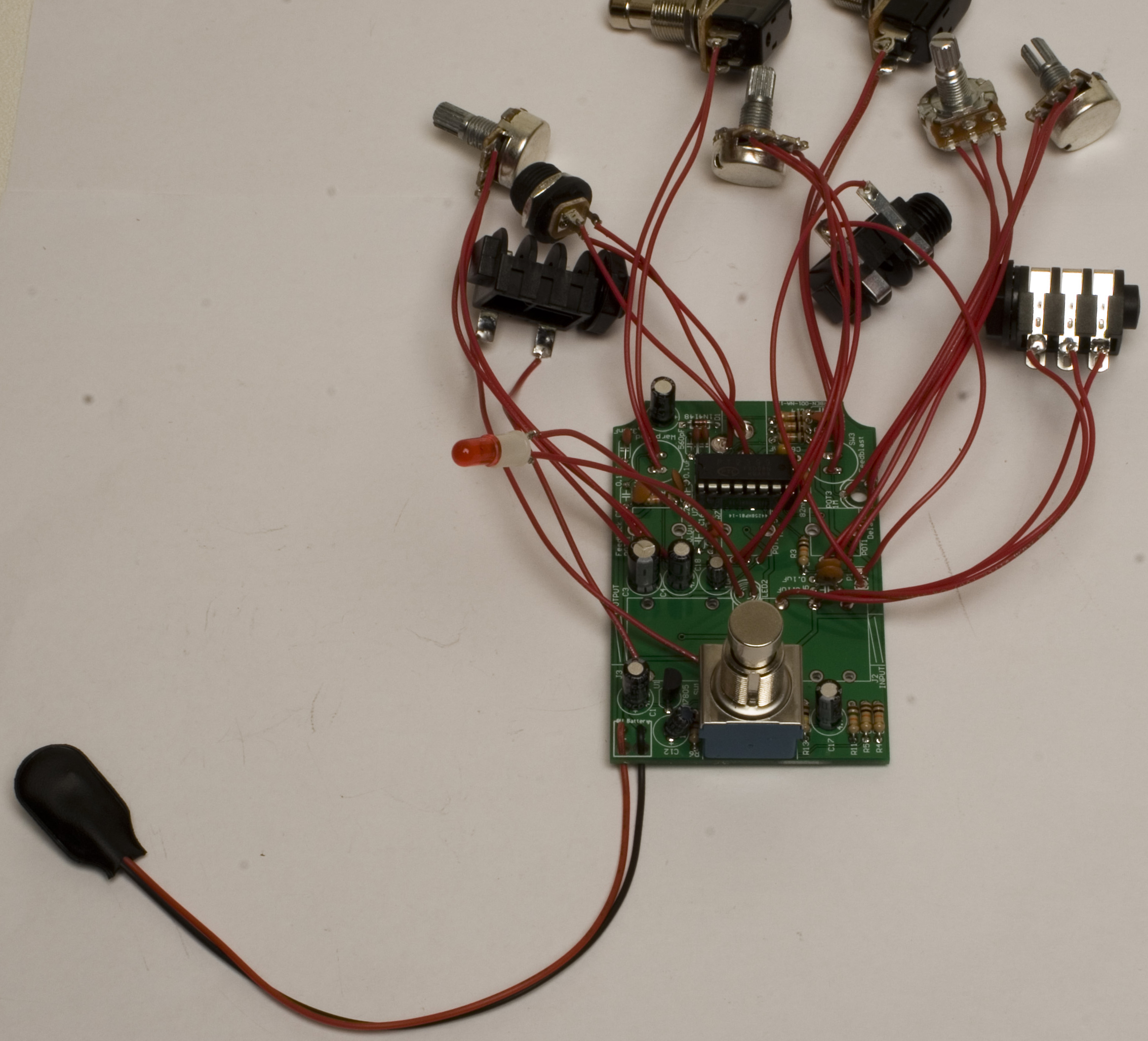
Cosmic Echo Squared Step 11: 9v battery clip and LED
Next up is the LED soldering. Slip the LED legs into the plastic bezel sleeve, and then solder wires to the leads. The wire that gets soldered to the flat side of the LED should get soldered into the corresponding via on the PCB. When putting the 9v battery clip on, slip the wires through the strain relief holes first, then down into the vias, like in the picture. Make sure the red goes in the + via, and black in the – via.
Case Prep
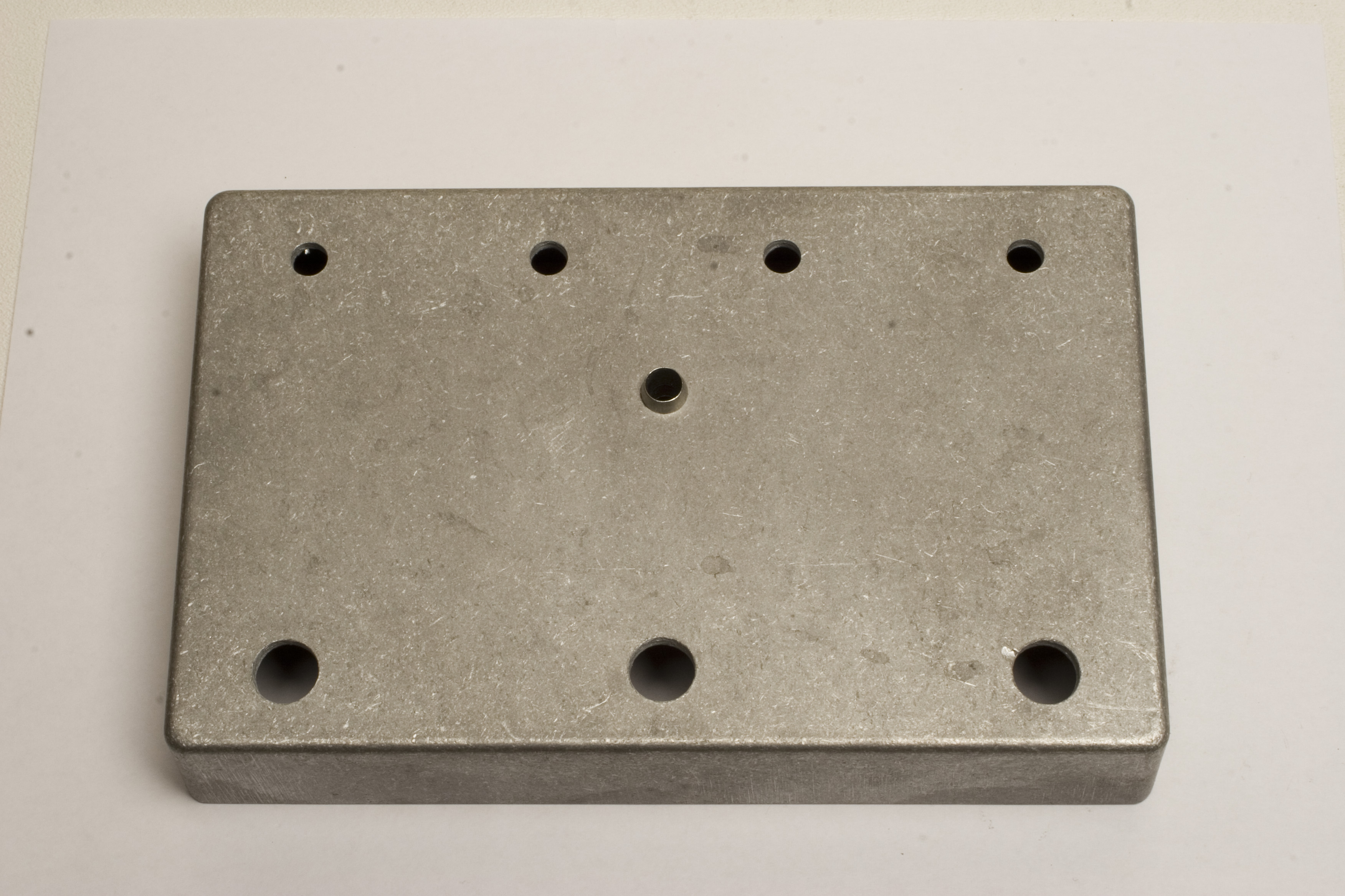
Cosmic Echo Assembly Step 12: Case Prep
Now we are ready to mount the board and components into the case, but first we need to attach the LED bezel to the hole in the middle of the case.
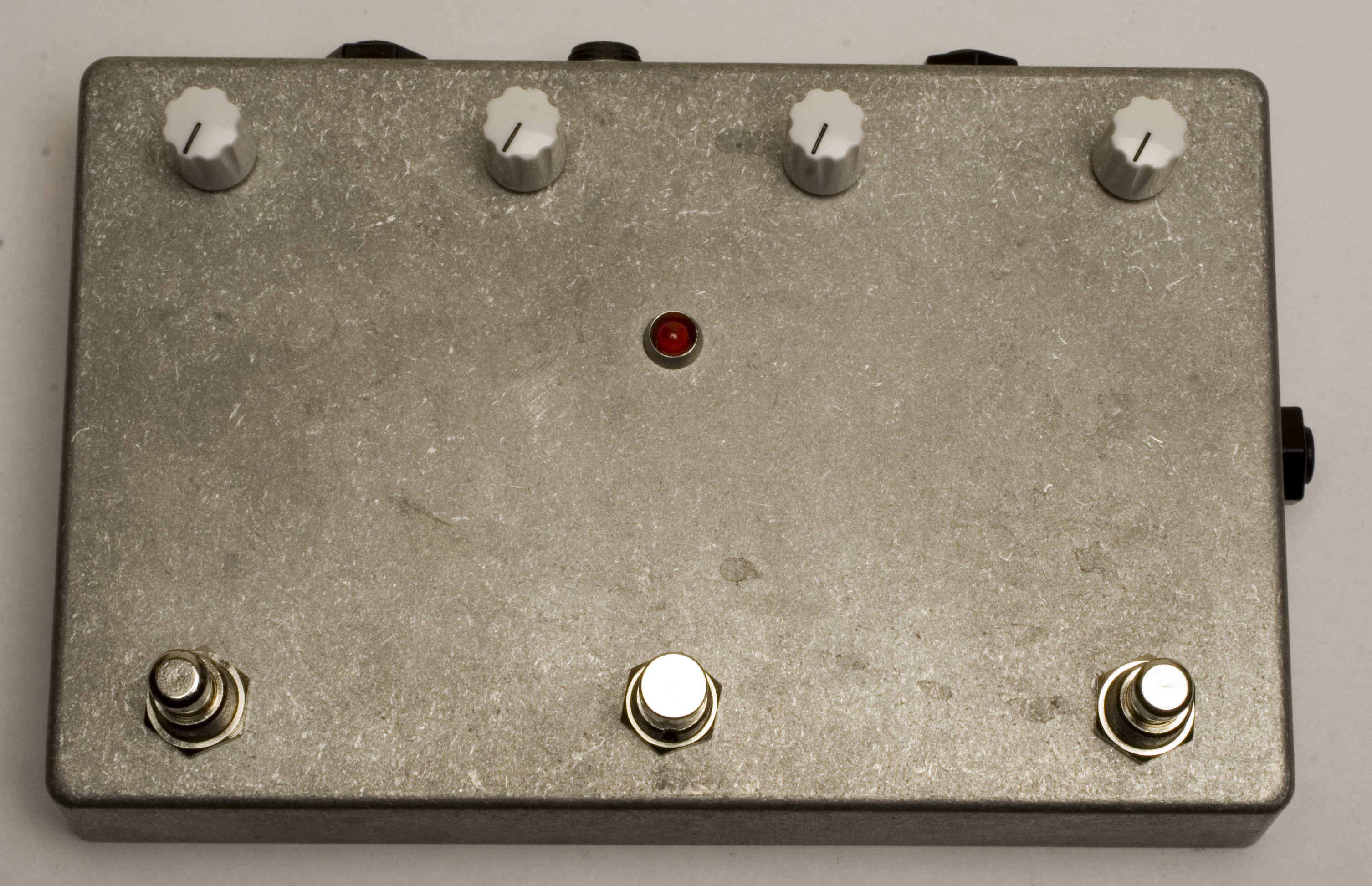
Final Assembly
Once the case is prepped with the LED bezel, we can start assembling the components into the case. The recommended order of parts is potentiometers first, in the top row. Then the jacks, with Input and Output on the top Right and Left. Expression pedal goes in the side. Then the momentary switches, in the bottom left and right holes, and finally the LED. You may need to put some electrical tape between the LED leads and the PCB to avoid anything touching and shorting out the circuit. Once the LED is in, you can mount the stomp switch to the bottom middle hole, and tighten it up. Make sure not to over-tighten any of the nuts, because they may cause premature failure of parts if you do. All that’s left is putting the knobs on now, and trying it out!
Optional Output Buffer Mod
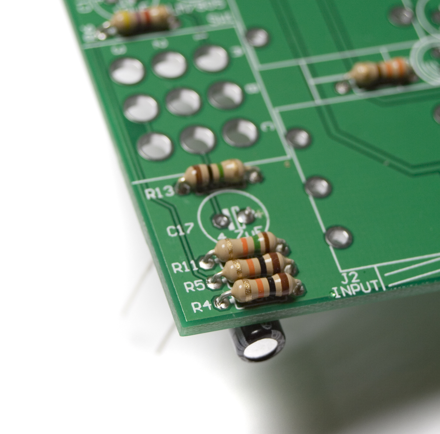
The first step before starting the buffer mod is populating all the resistors.
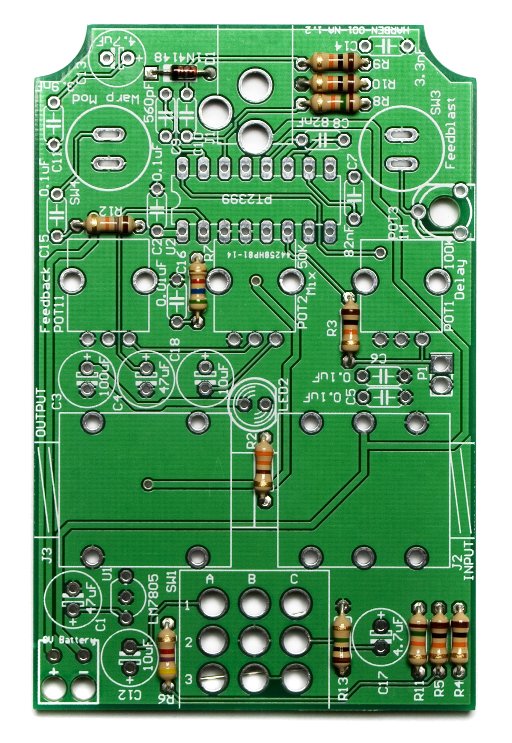
Cosmic Echo Resistors
Now flip the board over onto a hard surface and solder the legs in place. Clip all the leads EXCEPT R13.
R13 is NOT CLIPPED
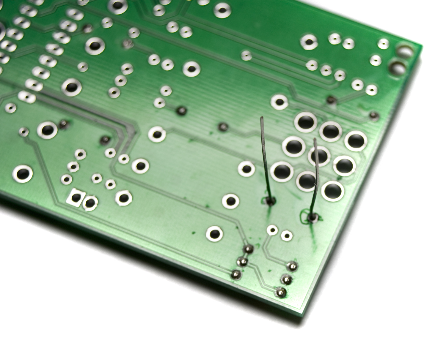
Place the positive lead of C17 through From the bottom of the board like pictured below, but do NOT insert the negative lead through its hole. Just bend it straight up to get it out of the way for now. Solder the leads, but don’t clip them yet.
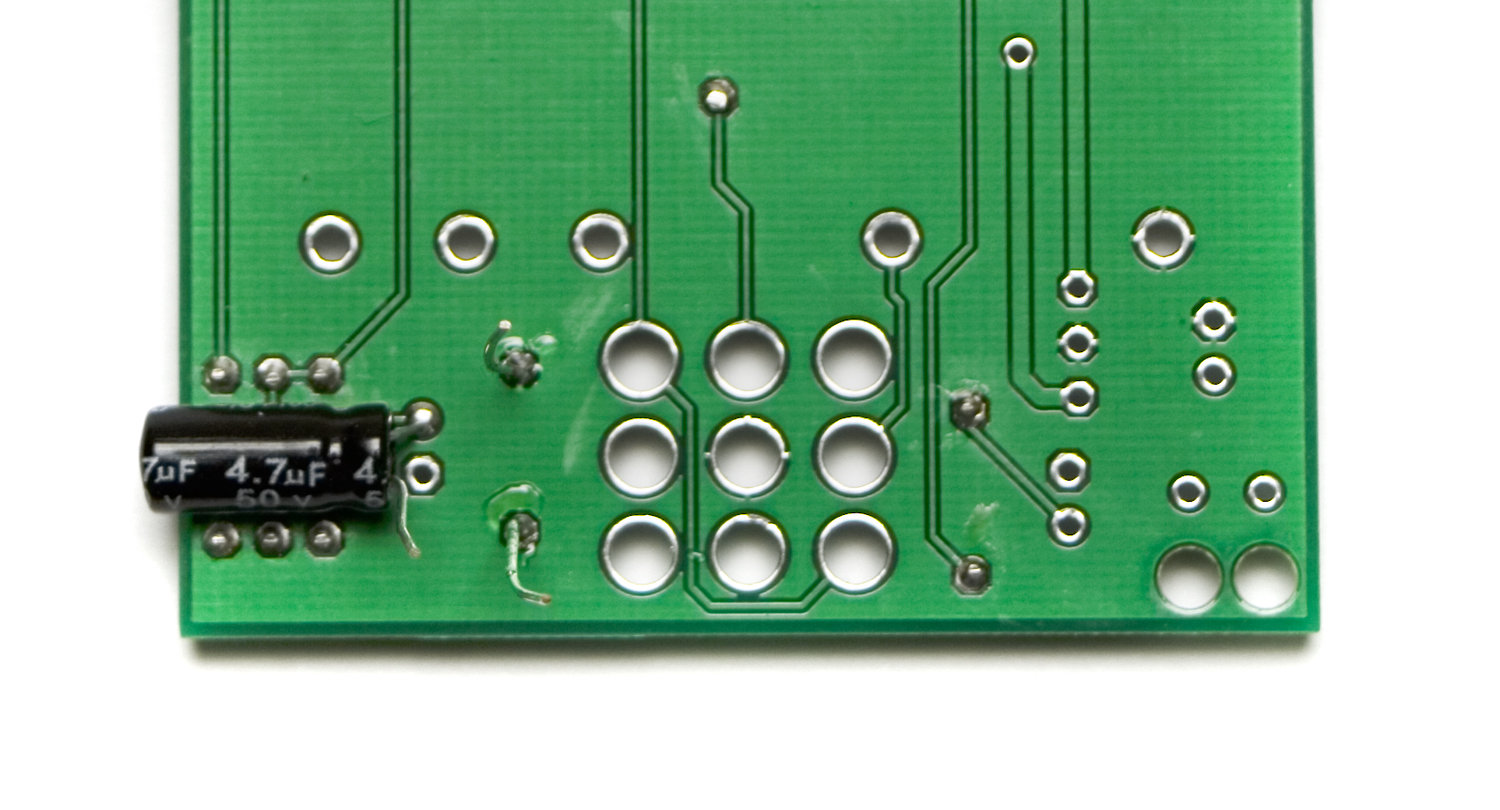
Capacitor Placement
C17 from the top side of the board.
The next part is a little tricky, so make sure you have it right before soldering.

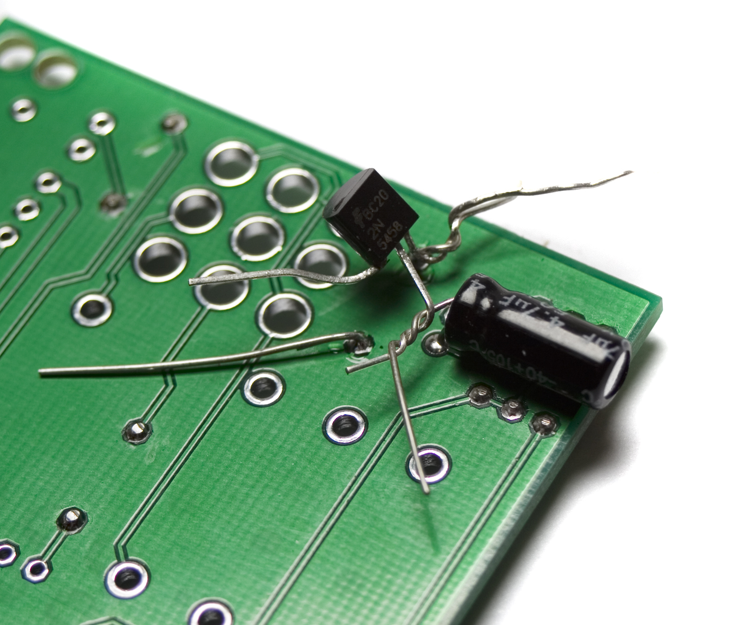
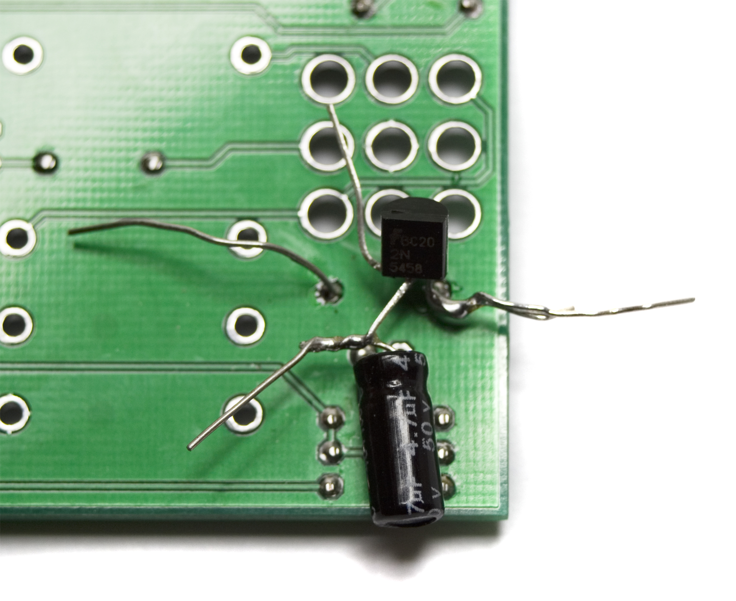
JFET Lead Orientation
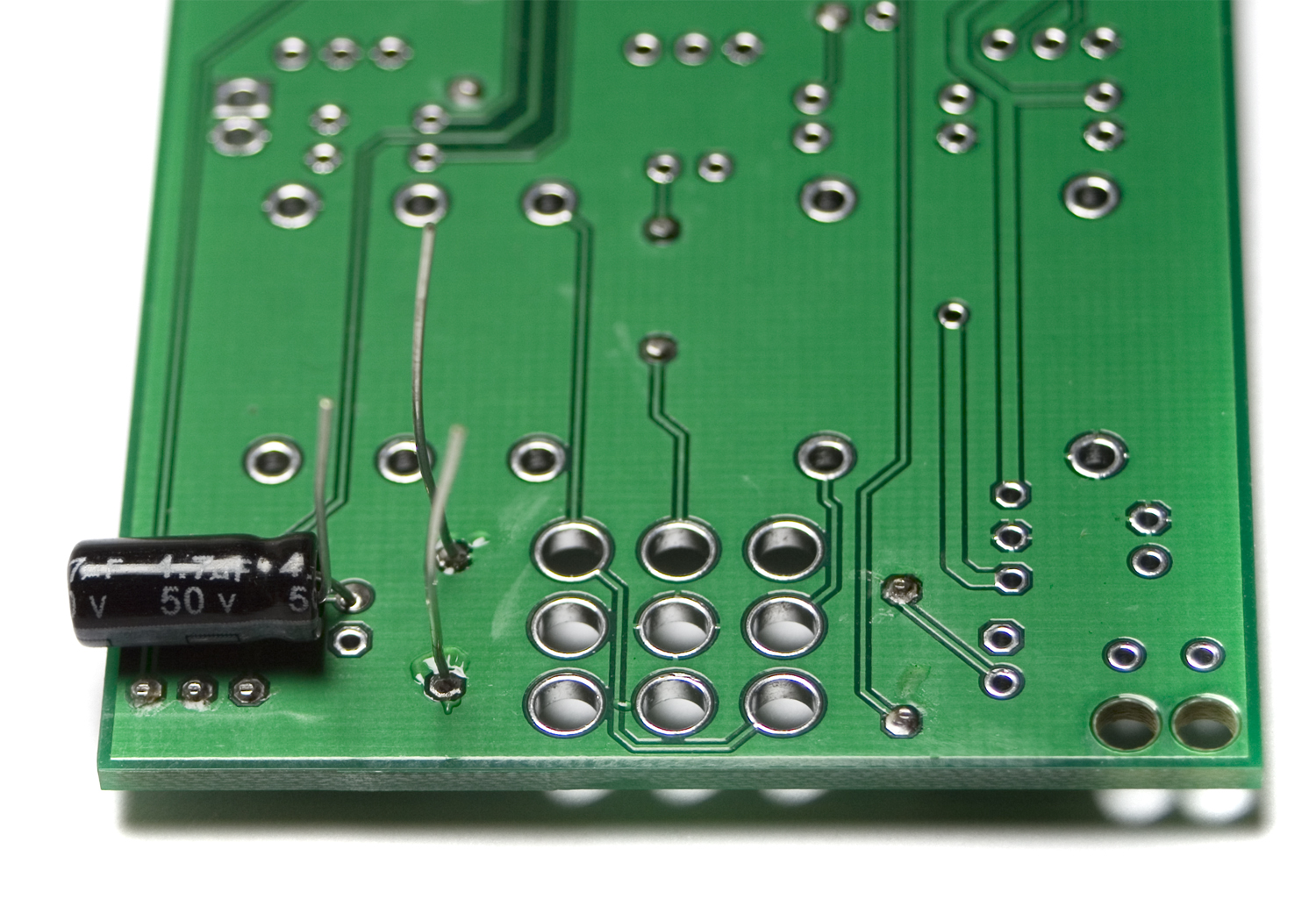
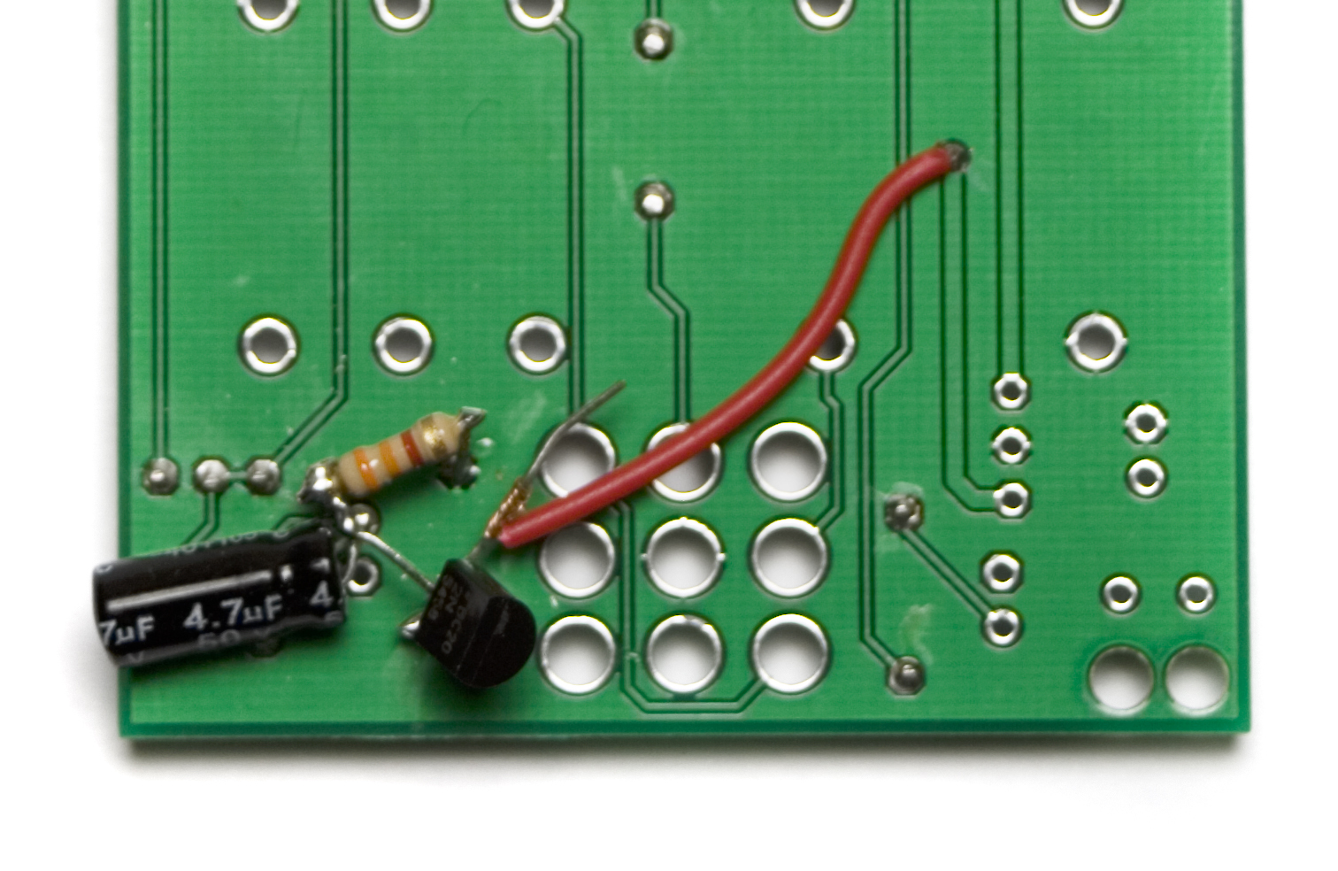
Take the JFET, and twist the ‘Gate’ lead (G in the picture above) with the side of R13 that is closest to the edge of the board. Then twist the ‘Source’ lead (S in the picture above) of the JFET with the negative side of the capacitor. Bend the ‘Drain’ lead (D in the picture above) straight up (or off to the side) to move it out of the way for now.
Now solder the leads. Don’t clip them just yet, though.
The Next step is to lay your 3.3k ohm resistor across the negative lead of the capacitor and the leg of R13 that you haven’t used yet as shown in the picture below.
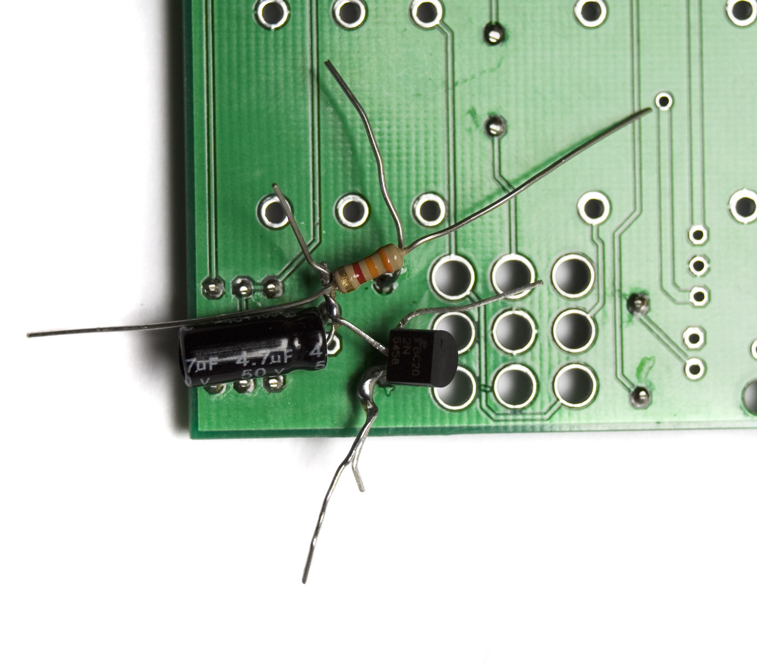
Now solder the resistor in place. You may need to enlist the help of someone to help hold the resistor in place while soldering.
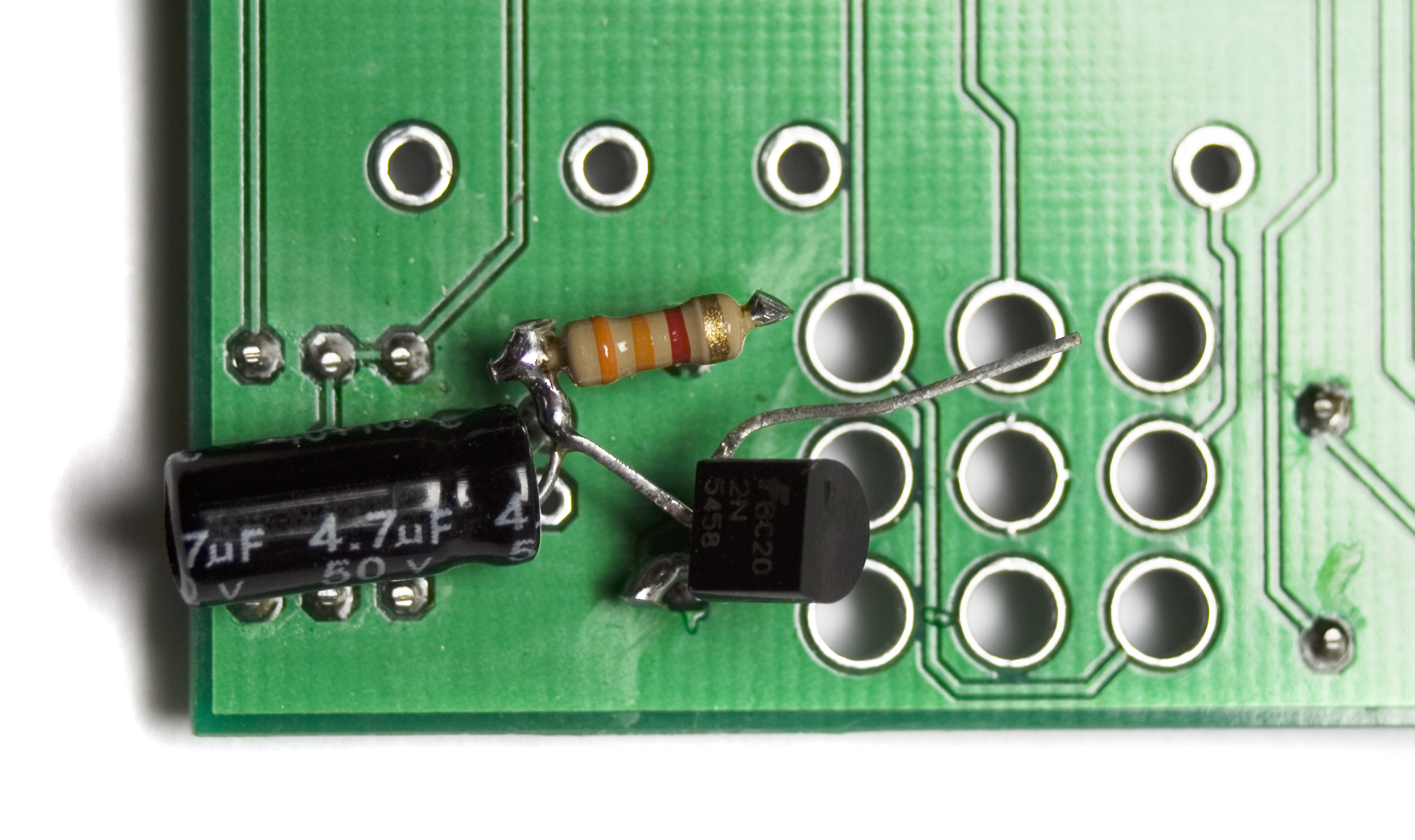
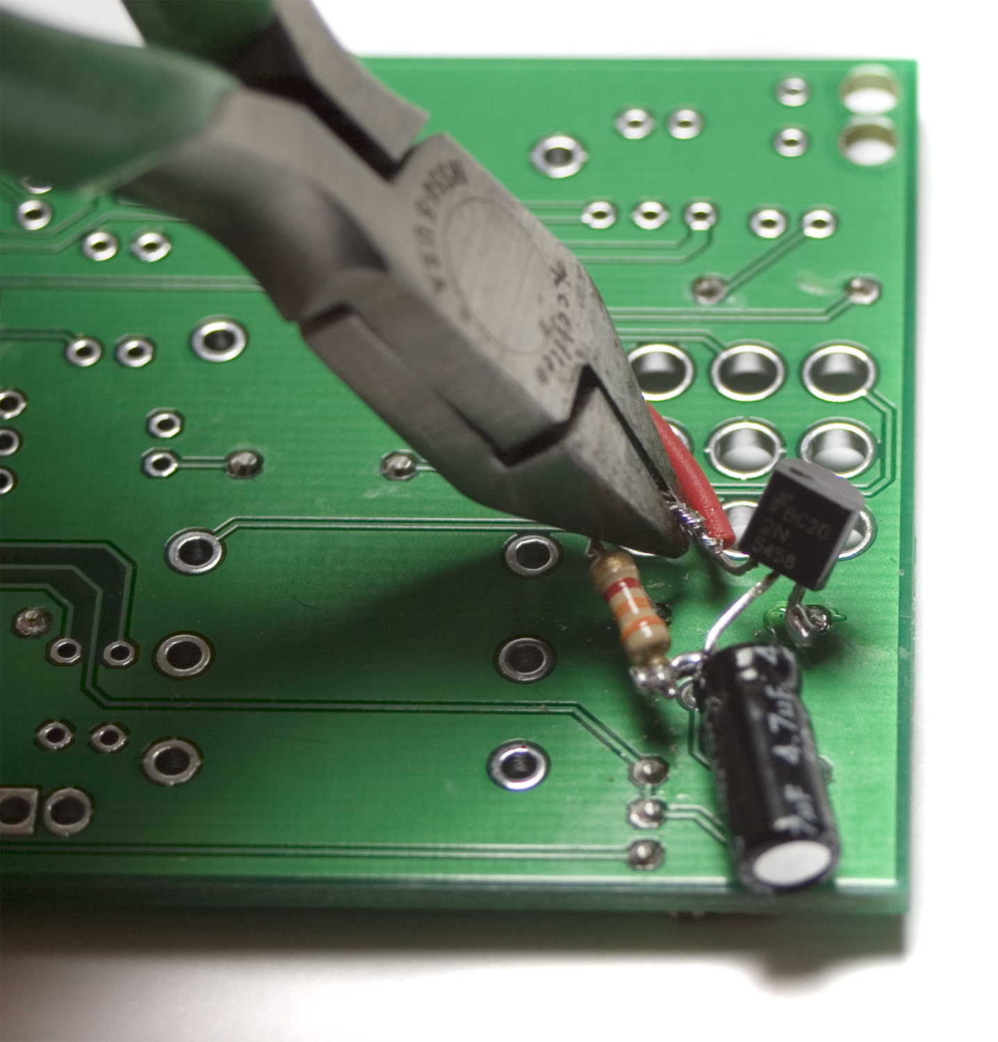
Clip all excess leads at this point. DO NOT touch the ‘Drain’ lead of the JFET yet. This is where we will be soldering out +9v source.
Next we will be soldering one side of the wire to the via that is in the middle of where the mono jack goes. Do this by stripping a little bit of casing off the end of the wire, and insert the bare wire through the via. (twist the wires first so they go in easier). Then solder it in place and clip any excess.
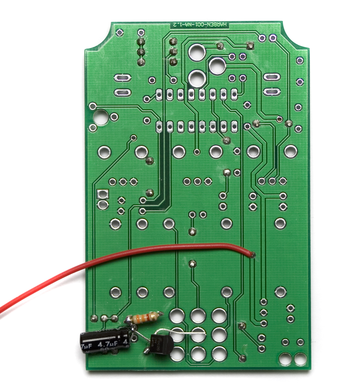
+9v Wire Location
Next up, trim the wire down so it is short enough to not interfere with the rest of the build. Strip a little bit of casing off the end, and twist the bare wire around the ‘Drain’ lead of the JFET as shown below.
Twist the wire around the ‘Drain’ leg of the JFET
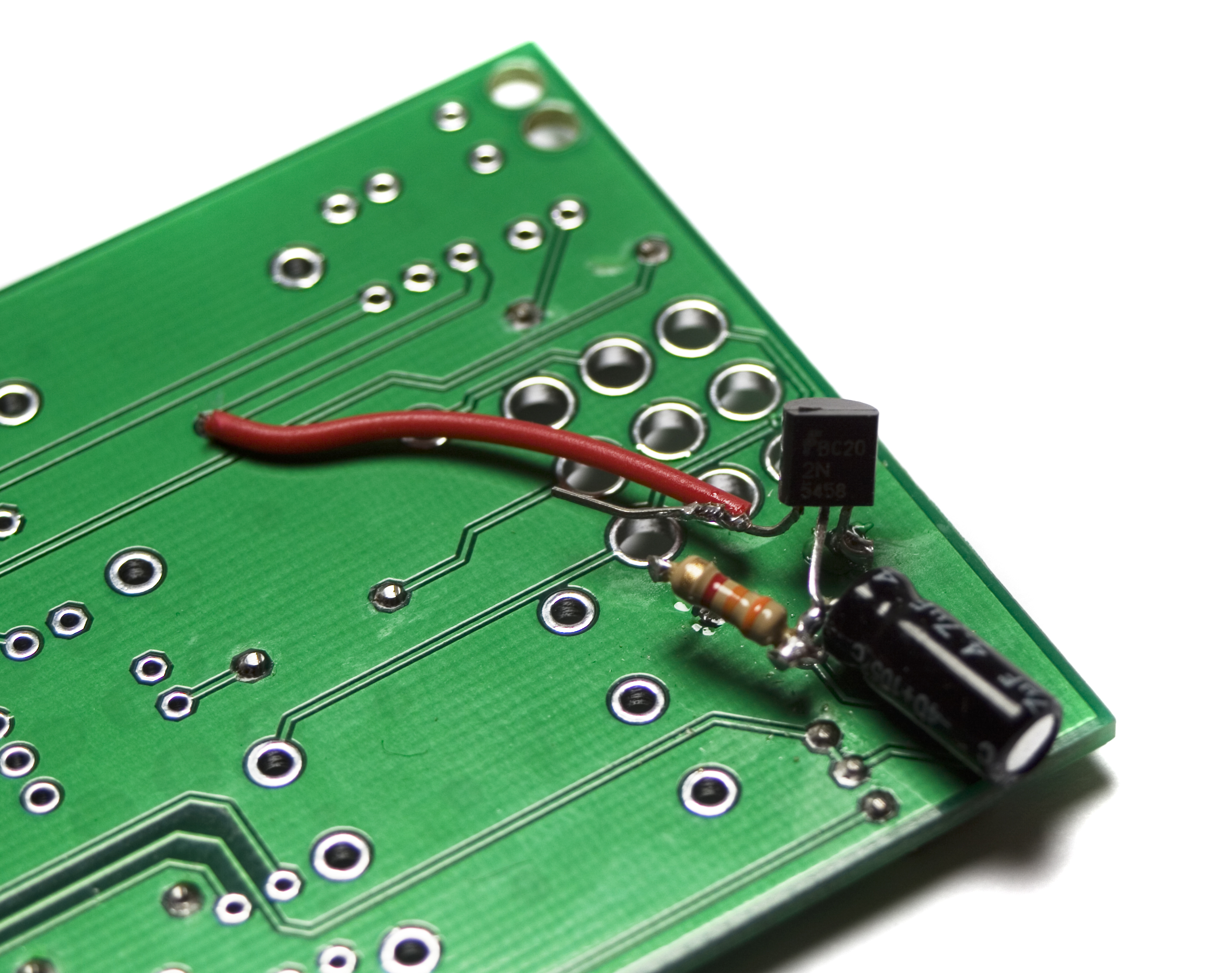
Another look at the JFET Wiring
Now you can solder the wire to the JFET and then clip the excess, as shown below.
You are now done with the output buffer mod for the Cosmic Echo Squared. You may return to the top of the page, and continue following the instructions. Don’t forget to solder in your diodes from the first step before moving on.
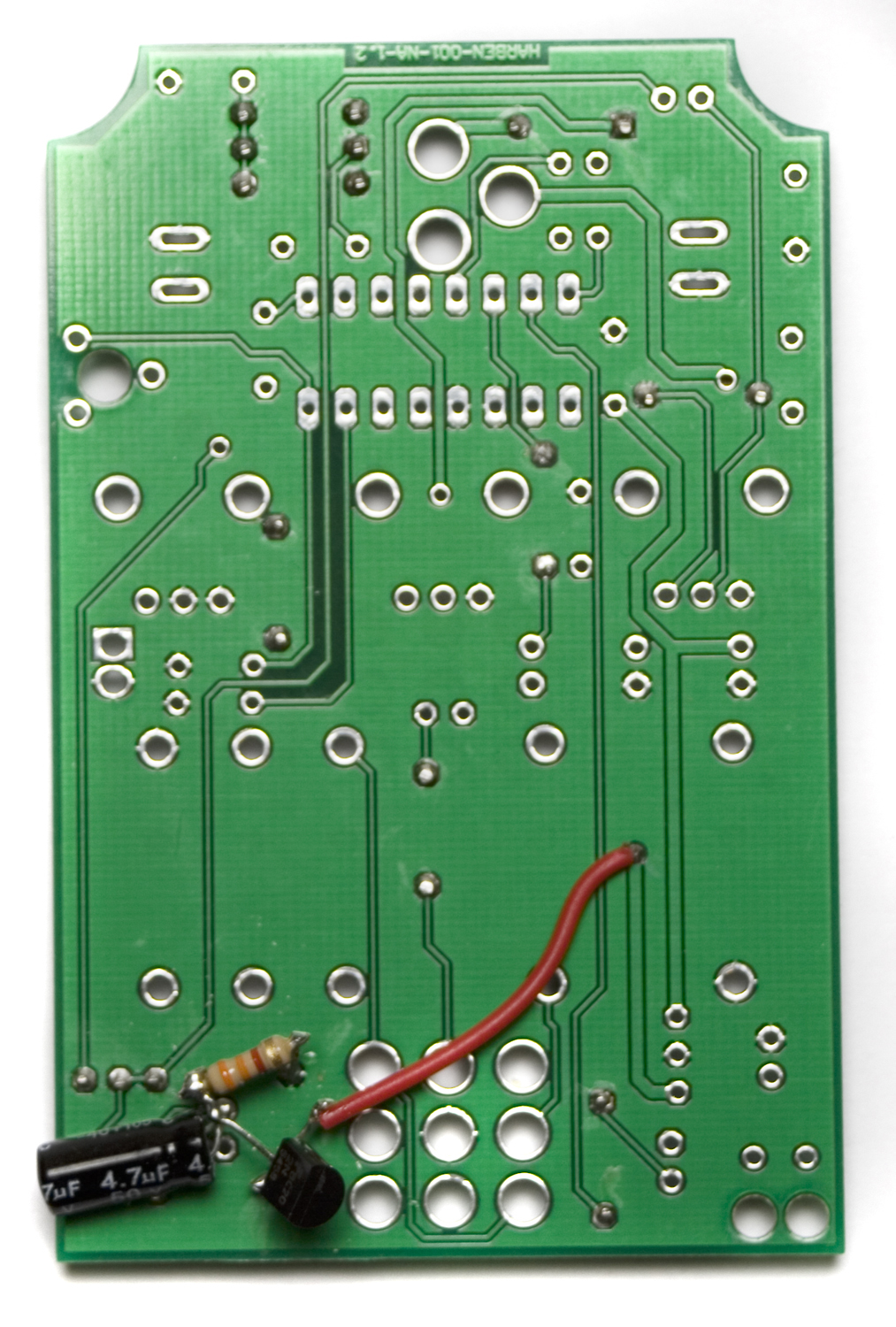
Completed Output Buffer Mod
How would I short the footswitch pads to make this allways on? Or rather have the on/off switch moved to earlier in the power supply chain (this unit would be built into another and share power supply and switch with other units).
@Buster
are you talking about shorting the middle stompswitch that turns the pedal on and off?
Yes, the other ones will be replaced by momentary push buttons. I’m incorporating this delay into a larger unit and want remove the stomp altogether. I’ll have a shared switch for the 3 boards in the unit.
Nevermind. I just realized that this is a very inconvenient place to ask questions. I took it to the facebook page instead.
@Buster
Hey Buster, sorry its taken a bit to get back to you. You can always email us at synthroteksales@gmail.com emails are easier for us to respond to rapidly. As for the switch, I think if you just take a multimeter to the stomp switch, you should be able to find out which pins connect and disconnect when you press it, and from there, it should be relatively simple to figure out which solder pads to jumper to get it in a ‘always on’ mode.
Ok, Thanks!
unfortunately mine cuts volume by about half even with the mod, therefore not much use in reality
“by half” is way more than any of our set-ups experience. Feel free to shoot an e-mail to store@synthrotek.com with some shots of the build and what environment you’re running the pedal through.
Hi there
Would it be possible to please upload a drill template for this build, thanks
Hi there, I am sorry, we don’t have one at the moment, but hopefully soon