


Important Links
Product Page
Store Page
Assembly Instructions
Bill of Materials
Schematic
Capacitor and Resistor Lookup Guide
The current Voice of Saturn Assembly Instructions are provided in a PDF file. The file is embedded into the page below and further below is a link to download the PDF file to your computer. In addition to the PDF assembly instructions please view the two images below to assist in your assembly if you have board revision 1.03. The BOM has been updated to reflect board revision 1.03.
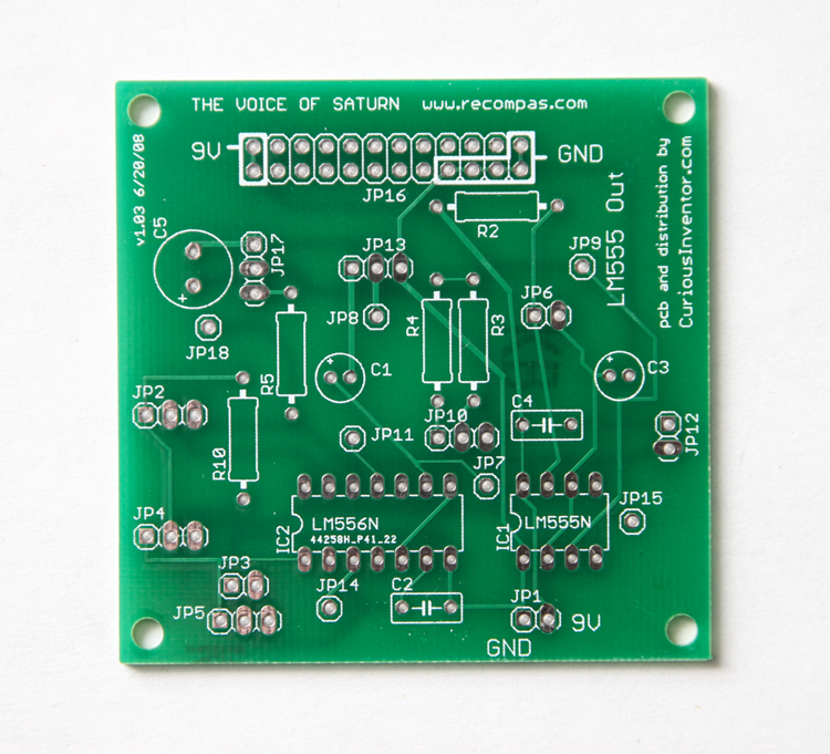
Voice of Saturn Synth Revision 1.03 PCB
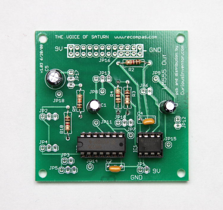
Voice Of Saturn Synth with all PCB Components added. V.1.03
Hey,
How do I connect the vactrol? It only has a white dot on one side.
Research sais its the negative of the LED, but what side is that supposed to go? To the jacks or to the pot?
Thanks!
@Ewoud
I put the little dot towards the jacks when I put this together recently(the assembly instructions suggest this, but aren’t entirely clear). It seems to work for me, but I am still learning about this synth, so I might have messed that up and just not noticed it yet.
Hey there,
Are you talking about the vactrol placement? The dot is supposed to go towards the CV jack. If it sounds fine, I would leave it alone unless it starts acting funny.
Best,
-Patrick at Synthrotek
I still can’t get this thing to work. That’s 3 out of 4 boards that i’ve purchased from you that don’t work because the lining comes off if you barely touch it.
Hey Nick,
I’m sorry you are having issues with your Voice of Saturn Synth kit.
By lining are you referring to the metal traces throughout the board? Or maybe the solder pads for components?
What temperature is your soldering iron set to?
I typically run my iron at 750°F and rarely apply heat to the pad for more than two seconds.
If your iron is not temperature controlled, be aware of how long you are leaving you iron on a pad and use lead solder.
Feel free to email us photos at store@synthrotek.com and maybe I can offer some more advice!
-Zach
Thanks, had a lot of fun with this!
A tip:
Diagram in instructions shows CV1+ wired to JP15 which controls LFO rate.
I wired CV1+ -> JP11 to control 556 2nd timer which controls pulse width. Can then hook CV1 to LFO Out and modulate pulse width.
A gotcha:
My LFO was not triggering with wiring in diagram. I had to jump 555 reset pin #4 to 9V to get it to function. I ordered the 555 specified in BOM (got TI TLC555CP).