Important Links
Product Page
Store Page
Assembly Instructions
Bill of Materials
Calibration Instructions
Quick Start Guide
Capacitor and Resistor Lookup Guide
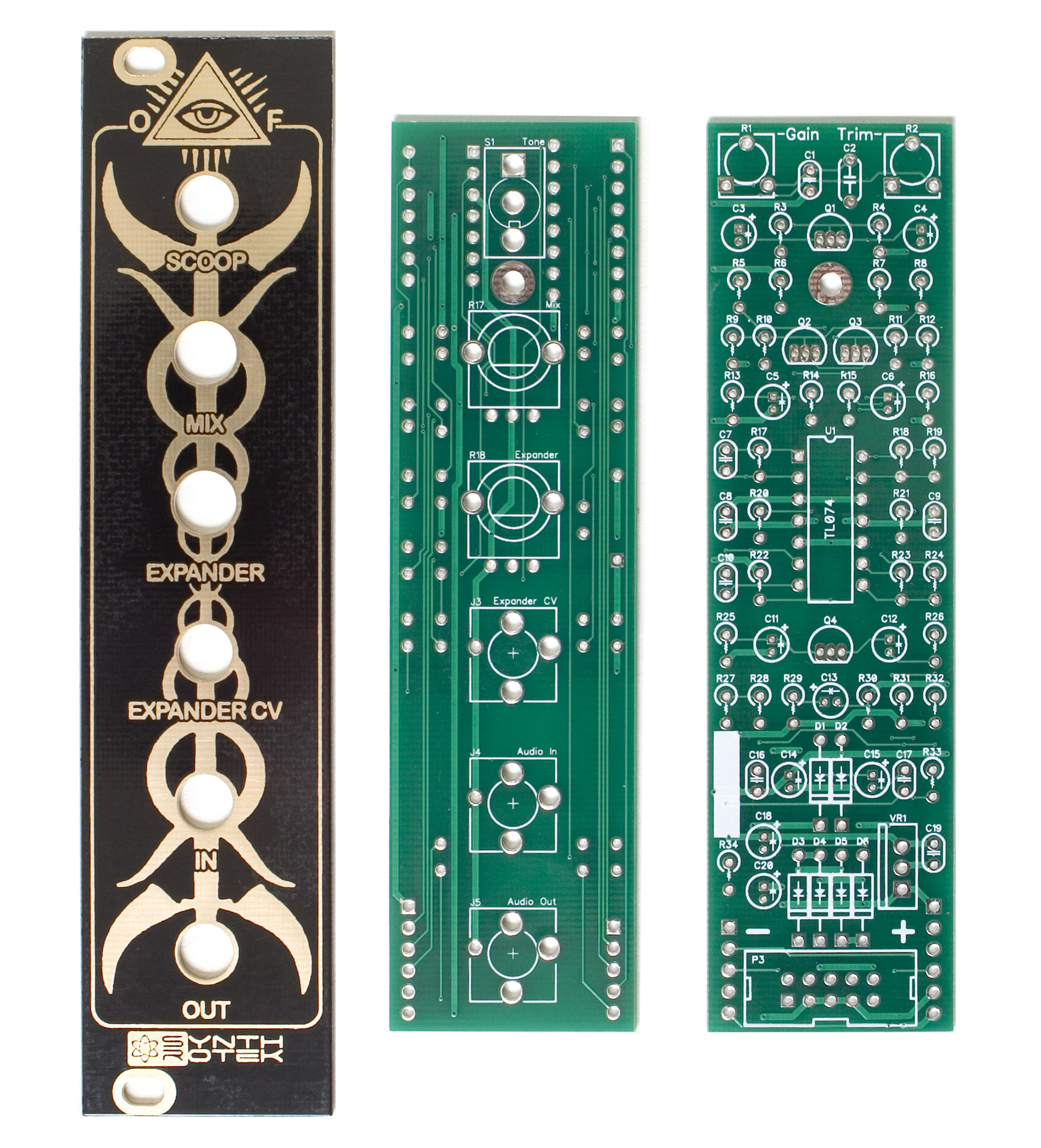
Thank you for purchasing the Synthrotek Octave Fuzz kit! This is an easy to intermediate build. It is very important to get all the components properly soldered into the PCB in the correct placement. If you feel like you can handle it, please proceed! If not, get some help from a friend with experience or purchase a fully completed unit.
Please build according to the BOM, and not these instructions or the pictures alone. Some components may have changed since these were written, or we may not be able to get the proper components in the pictures.
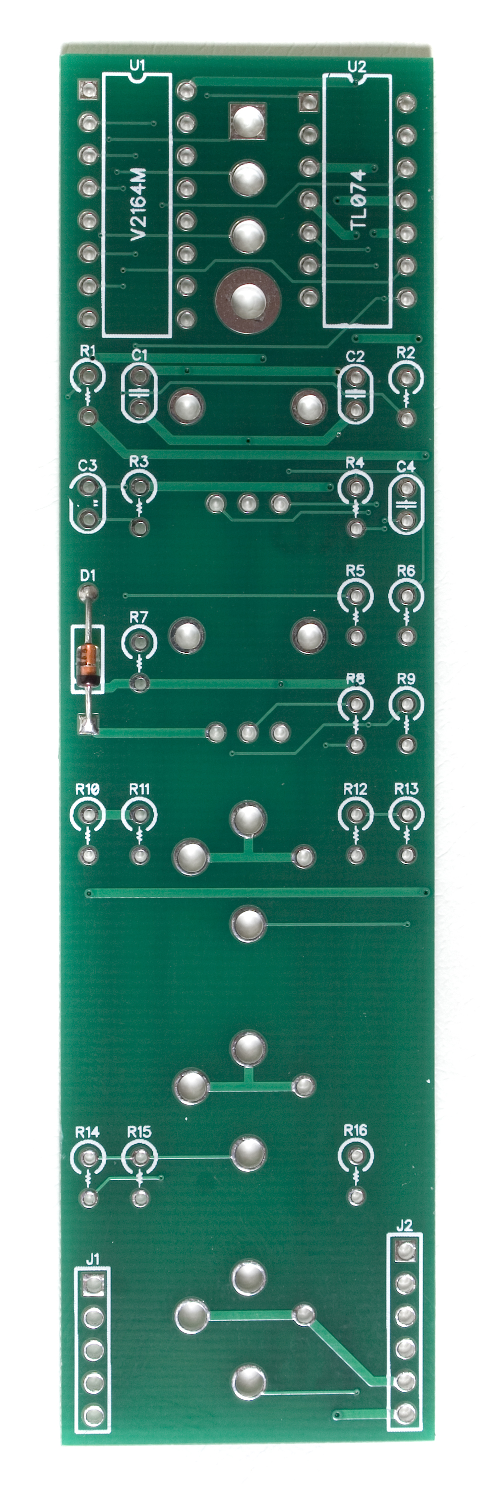
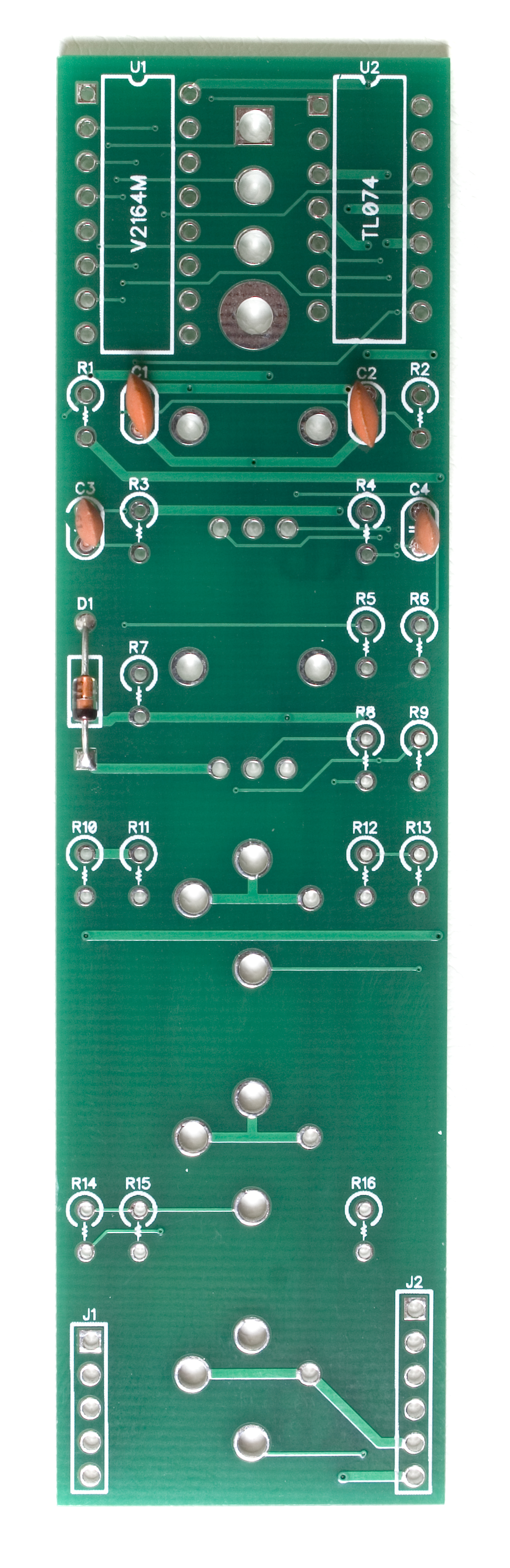
Logic Board Diodes
First thing we are going to populate is the diodes on the logic board. Following the BOM, insert all the diodes into their proper spots, paying attention to the polarity. Diodes are polarized components, and must be populated correctly to function. Make sure to align the cathode stripe on the diode with the cathode marking on the silkscreen.
Then you can flip your project over onto a flat surface and solder all the diodes in place. Then clip the excess leads.
 Logic Board Ceramic Capacitors
Now we can populate all the ceramic capacitors. These are non-polarized, so it doesn’t matter which way they are placed in the board, but to make troubleshooting easier, its recommended to place them in such a way that they can be easily read later on. Once you have them all in, carefully flip your project over and solder everything in place, clipping any excess leads.
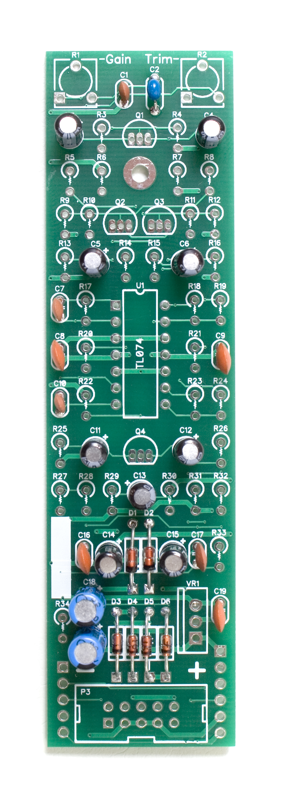
Logic Board Electrolytic Capcitors
Next up is the electrolytic capacitors. These components are polarized, so make sure when you are placing them, that you get the longer leg in the square hole, that is closer to the + symbol. Once in, flip your project over, solder and clip any excess leads.
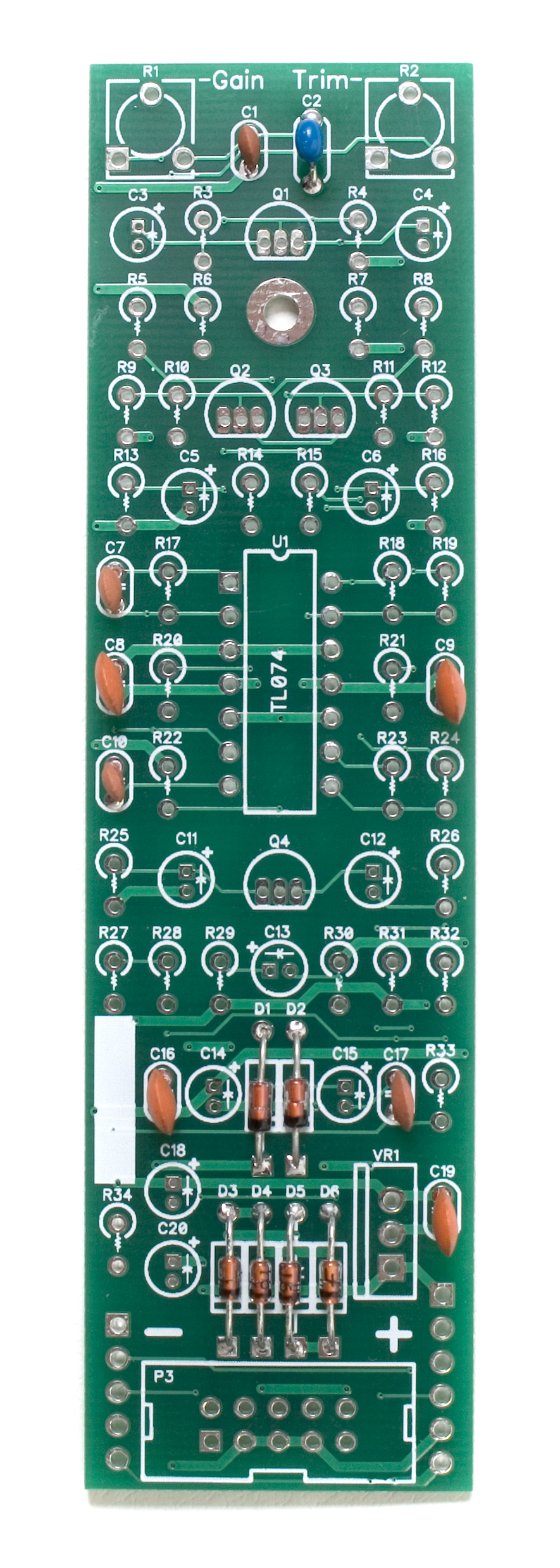
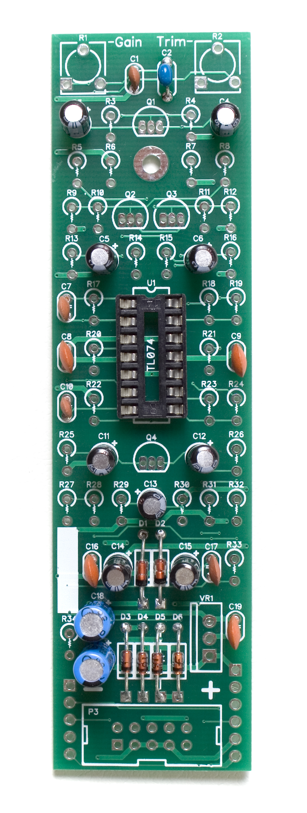
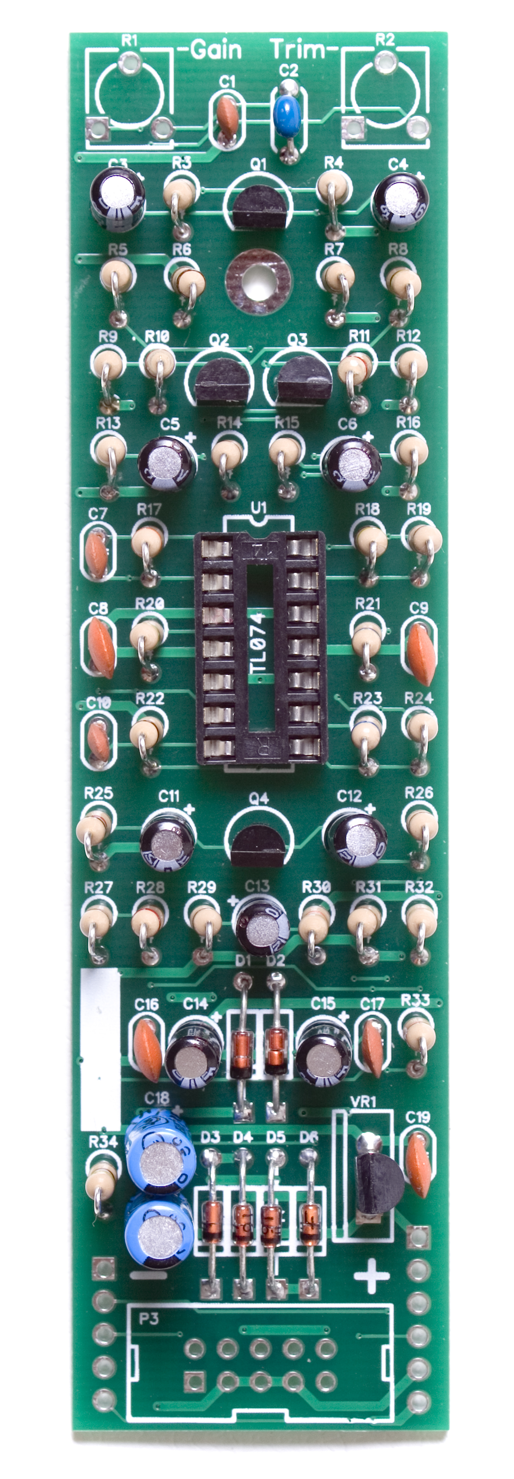
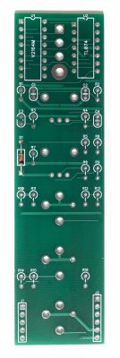
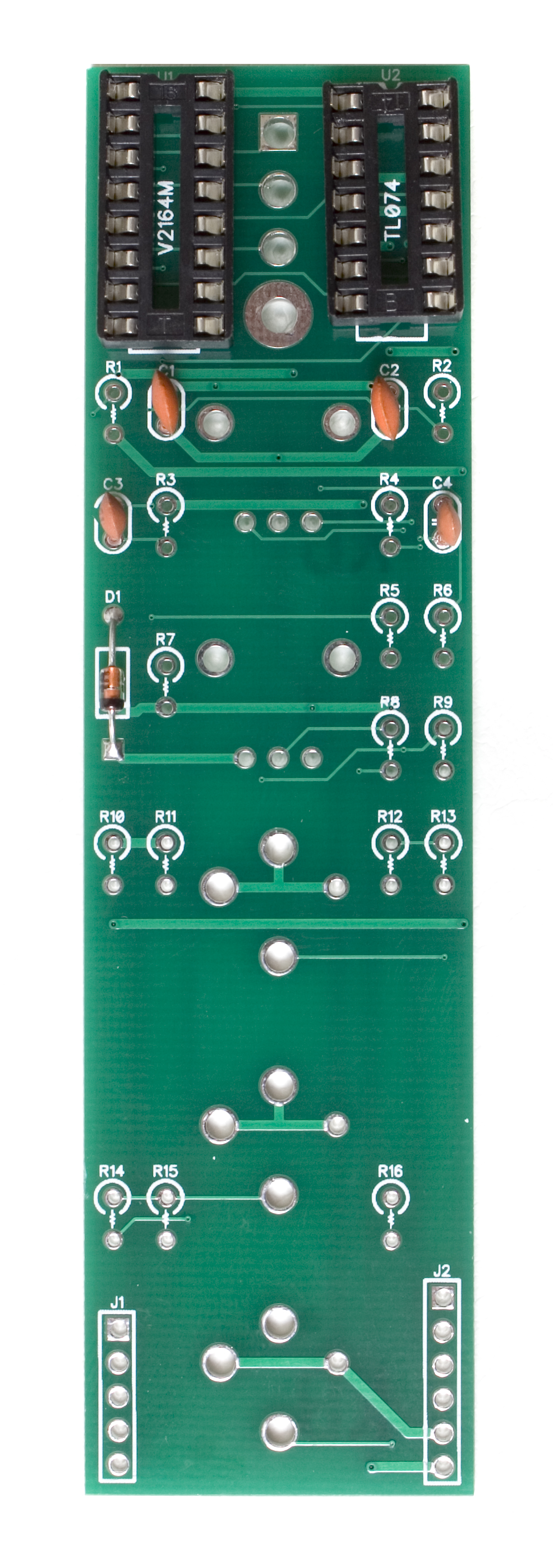
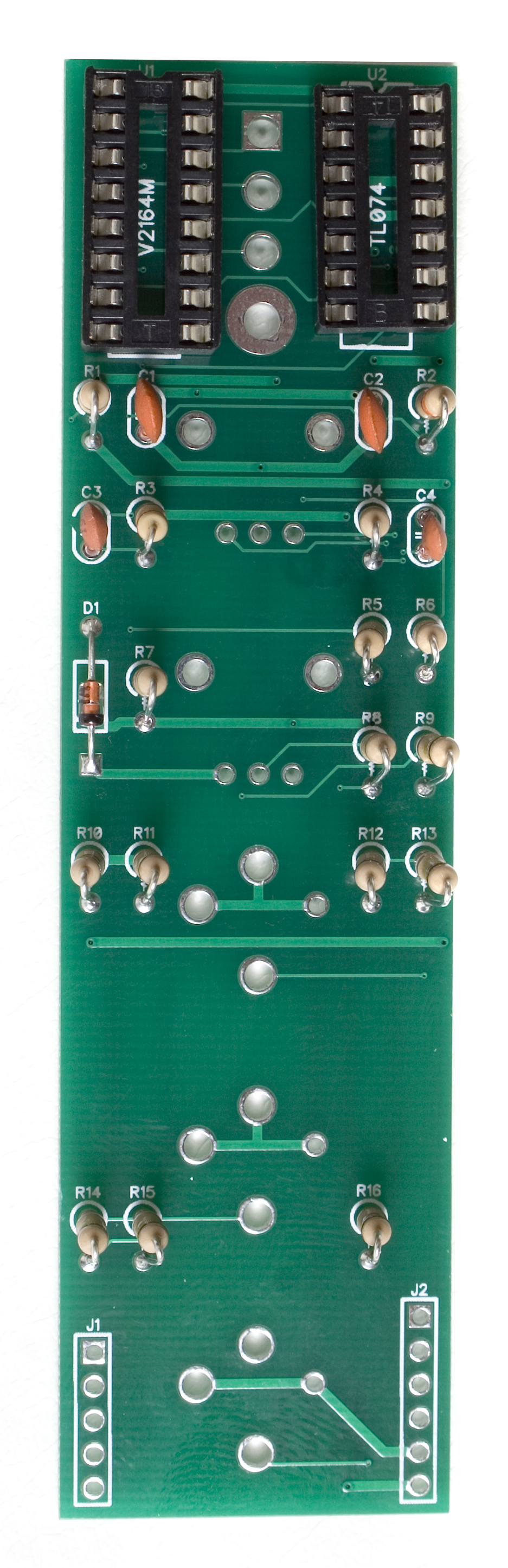
 Logic Board IC Socket
IC Sockets are next up on the list. When populating them, make sure to align the semi-circular notch in the socket with the same looking notch in the silkscreen. Once you have them in there, an easy way to get them flat is to only solder one leg of each. Then you can go back and reheat the solder points and gently apply pressure to sit them flat. Then go back and solder all the remaining legs on the IC sockets.
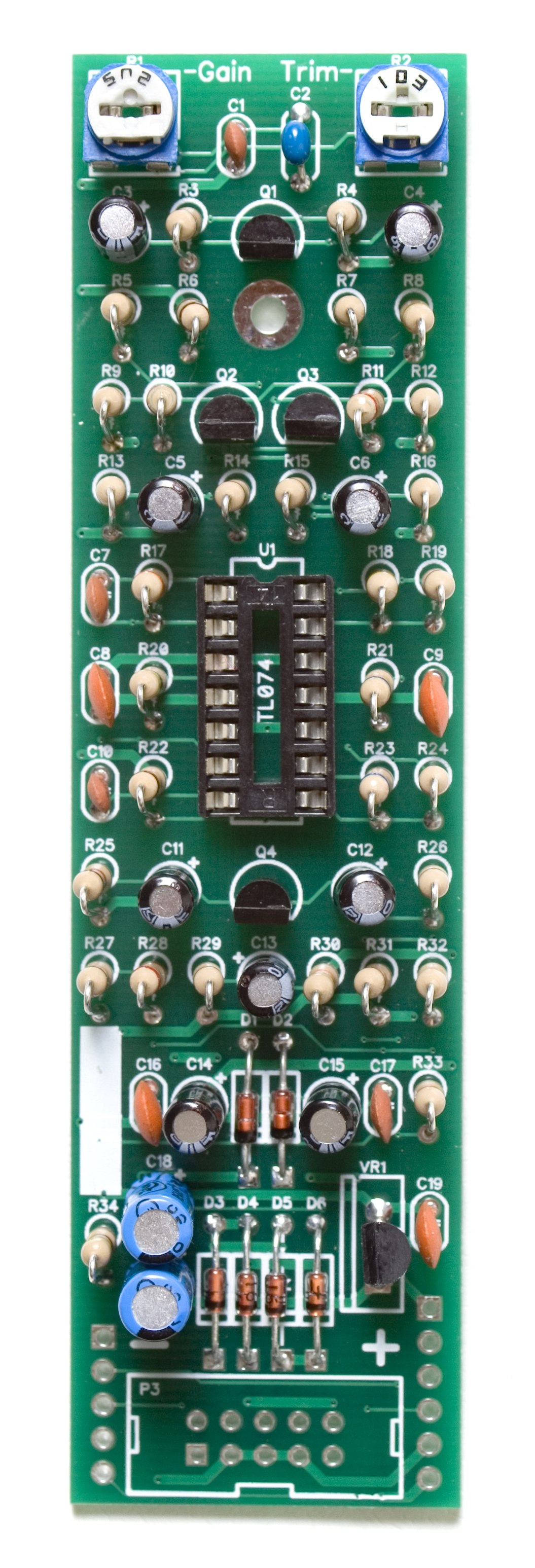
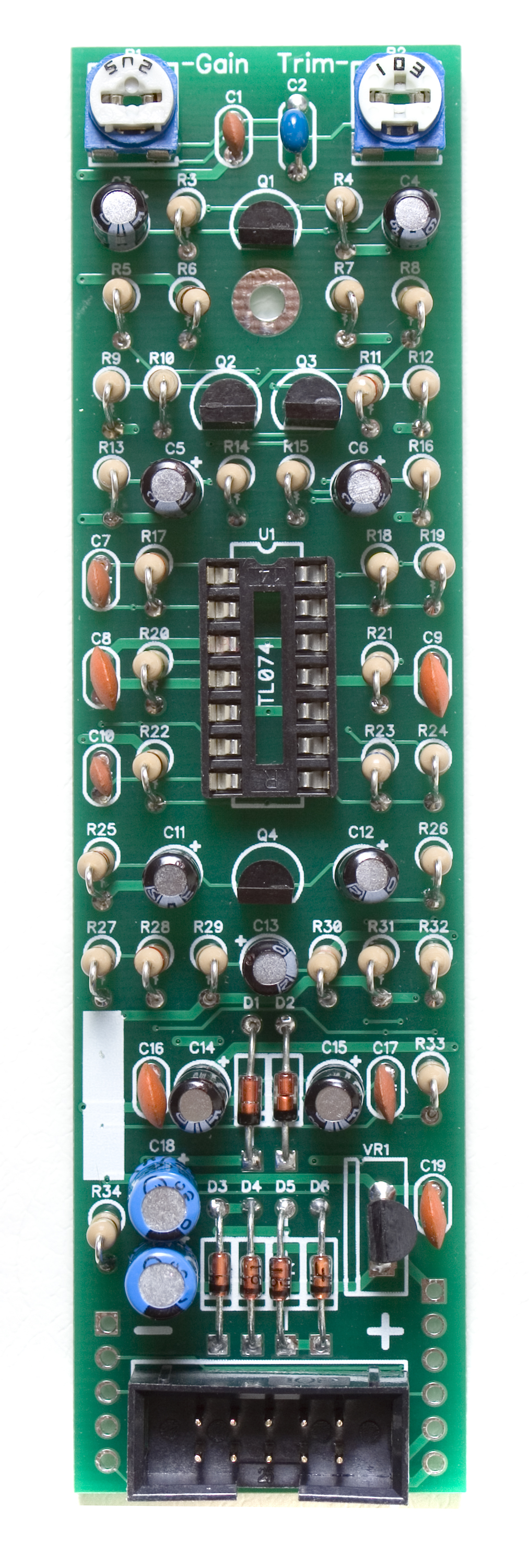
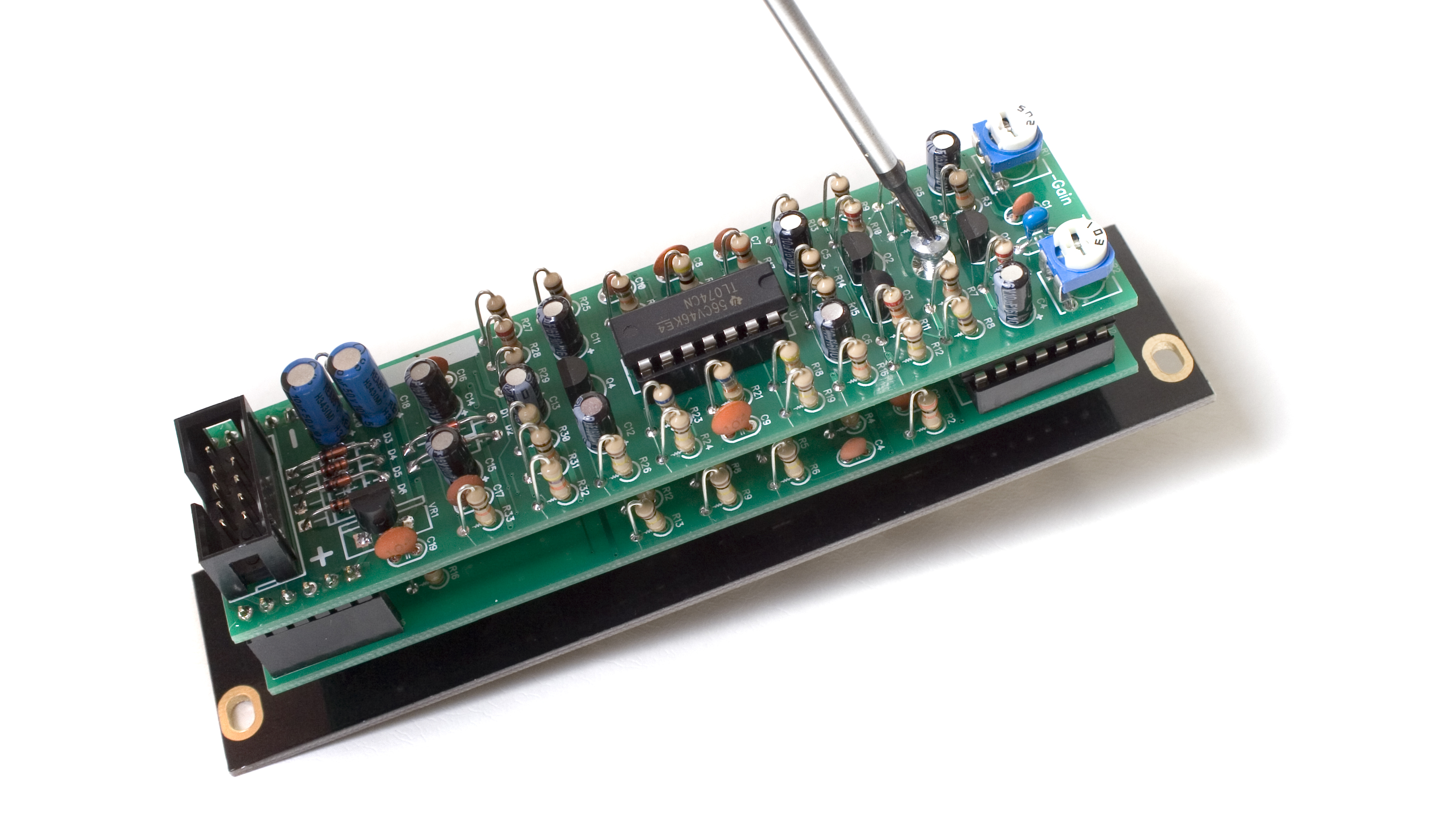
 Logic Board Transistors and Voltage Regulator
When populating the transistors, make sure to align the flat side of the transistor with the indicated flat side on the PCB.
Next up is the voltage regulator. The silkscreen on the PCB looks different than the actual voltage regulator, but the smaller regulator fits just fine. Make sure when you are populating it that you align the flat side of the regulator lines up with the extra line indicated on the PCB. (see photo below)
Once everything is populated as per the BOM, carefully flip your project over and solder everything in place, clipping any excess leads.
 Logic Board Resistors

Next up are the resistors, which are not polarized so it doesn’t matter which way they are placed in, but it makes troubleshooting a lot easier if you line up all of the tolerance bands (usually a gold stripe) on the same side. Insert each resistor, matching the value to the proper spot as per the BOM.
Once they are all in there, carefully flip your project over and solder the resistors in place. Clip any excess leads.
 Logic Board Trimmer Potentiometers
Now we can populate the trimmer resistors. They should only fit into the board one way, but ensure when you populate them, that the single leg is towards the top of the PCB. When they are populated as per the BOM, carefully flip your project over and solder them in place.
 10 Pin Power Header
Now we can populate the 10 pin power header. Make sure to align the notch in the headers with the notch indicator shown on the PCB.
It is recommended to only solder one pin of the power headers, and then reheat the solder joint while moving it, so that it can be positioned more easily. Once you have everything lined up and looking good, go ahead and solder the rest of the pins on the header.
5×1 and 6×1 Headers
Next up are the board to board connectors that are on the back side of this PCB. Populate them as per the bom, and then solder just one leg in place.
Then, while re-heating the solder joint, re align the header so that it is sitting flat and straight. Once you are happy with their position, solder the remaining pins.
 Control Board Diodes
Now we can move on to the control board. First thing we are going to populate is the diode. Following the BOM, insert the diode into their proper spots, paying attention to the polarity. Diodes are polarized components, and must be populated correctly to function. Make sure to align the cathode stripe on the diode with the cathode marking on the silkscreen.
Then you can flip your project over onto a flat surface and solder all the diodes in place. Then clip the excess leads.
 Control Board Capacitors
Now we can populate all the ceramic capacitors. These are non-polarized, so it doesn’t matter which way they are placed in the board, but to make troubleshooting easier, its recommended to place them in such a way that they can be easily read later on. Once you have them all in, carefully flip your project over and solder everything in place, clipping any excess leads.
Control Board IC Sockets
IC Sockets are next up on the list. When populating them, make sure to align the semi-circular notch in the socket with the same looking notch in the silkscreen. Once you have them in there, an easy way to get them flat is to only solder one leg of each. Then you can go back and reheat the solder points and gently apply pressure to sit them flat. Then go back and solder all the remaining legs on the IC sockets.
 Control Board Resistors
Next up are the resistors, which are not polarized so it doesn’t matter which way they are placed in, but it makes troubleshooting a lot easier if you line up all of the tolerance bands (usually a gold stripe) on the same side. Insert each resistor, matching the value to the proper spot as per the BOM.
Once they are all in there, carefully flip your project over and solder the resistors in place. Clip any excess leads.
Control Board Female Sockets
Next up are the board to board connectors. Populate them as per the bom, and then solder just one leg in place.
Then, while re-heating the solder joint, re align the header so that it is sitting flat and straight. Once you are happy with their position, solder the remaining pins.
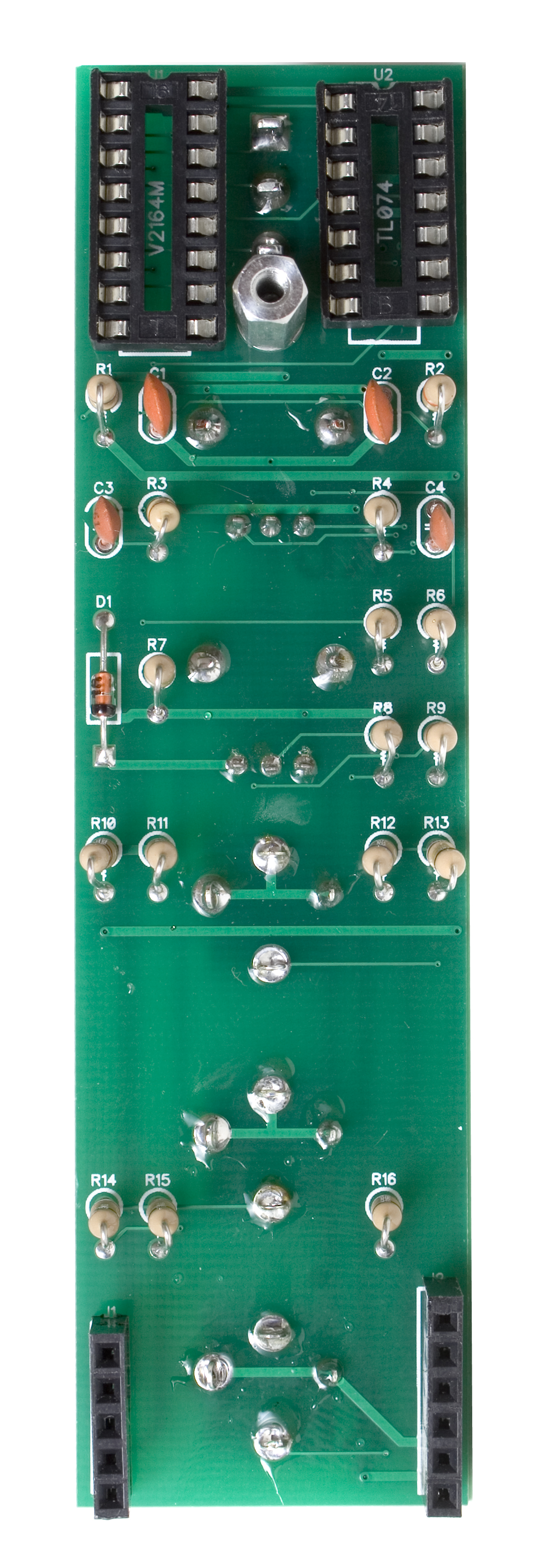
 Control Board Hex Spacer

Next up is the hex spacer that sits between the two PCBs. Insert the spacer screw (2.5mm) through the hole, from the same side as the IC sockets, and hold it with a finger as you twist the spacer down onto the screw. When it is tight, hold the spacer, and give the screw a gentle twist with a screwdriver to ensure it doesn’t loosen back up.
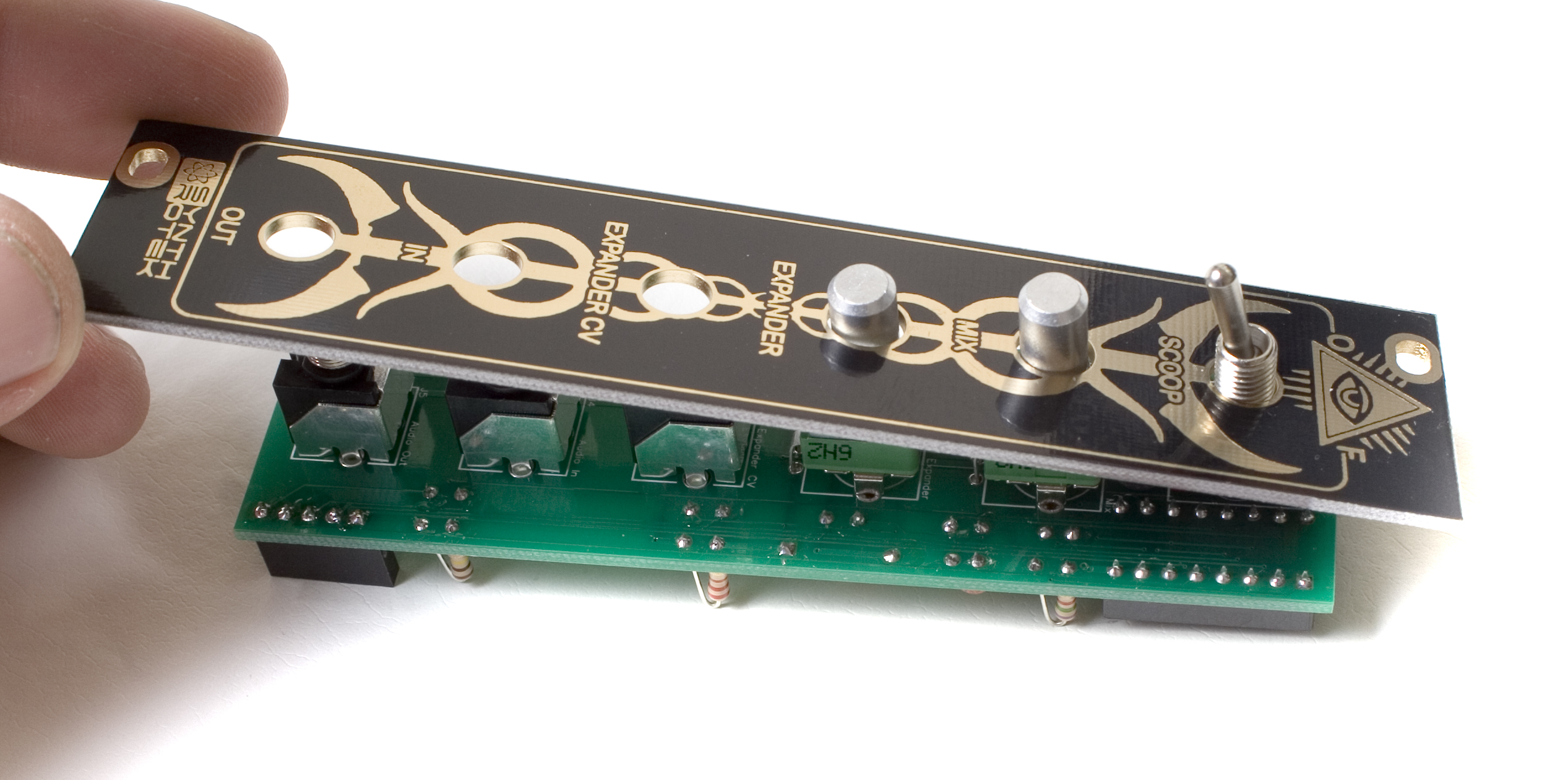
Front Panel Placement
Next, we are going to populate all of the hardware that connects the control board to the front panel. Populate all the jacks, potentiometers and the switch, following the BOM for placement, but DONT solder them yet.
Gently place the front panel down onto the hardware, making sure that everything lines up okay.
Then take a socket or other tool, and tighten the nuts down on everything.
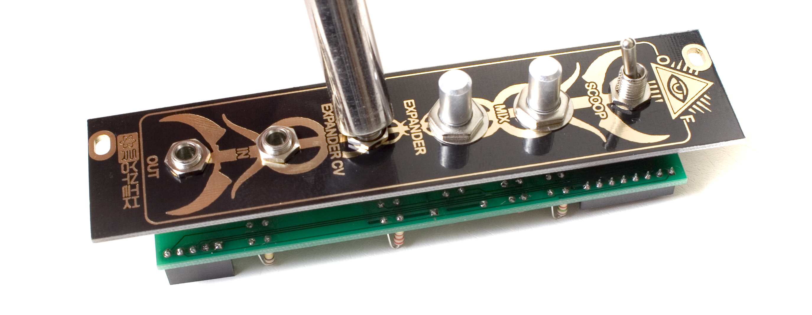 Once everything is tightened down, ensure that your front panel and PCB are straight and parallel, and then solder everything in place.
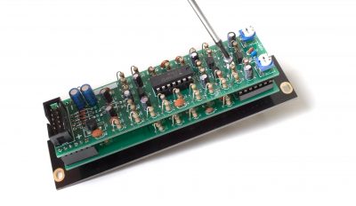
Final Assembly
Now we can mate the two assemblies together. Carefully line up the male headers on the logic board with the female sockets on the control board, and gently push them together, ensuring that the hex spacer lines up with the hole in the logic board.
Next, take a small phillips head screwdriver and the other spacer screw (2.5mm) and insert it through the hole in the logic board. Then tighten the screw down, securely mounting the two boards together.
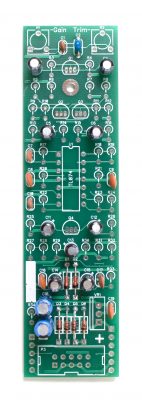
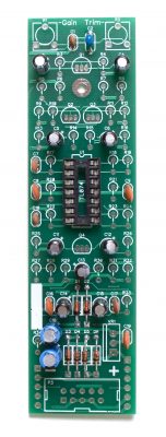
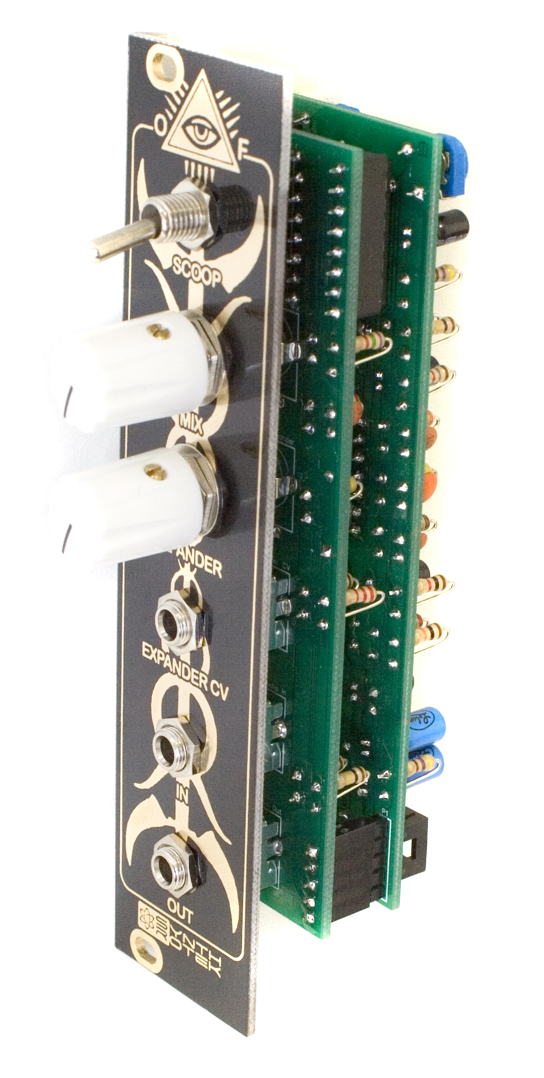
 Completed Unit
Congratulations! You have completed assembly on the Synthrotek Octave Fuzz Eurorack Module.
Thanks for choosing Synthrotek!
QC Instructions
Now that you have finished building your Octave Fuzz, it’s time to see if it is functioning properly.
First, patch a clean audio signal into the IN jack.
Next, either plug the Octave Fuzz into your output mixer, or plug your headphones directly into it.
Turn the mix all the way CW, and sweep the Expander knob back and forth. You should hear the output of the Octave Fuzz change as you sweep the knob back and forth.
Patch a CV input into the Expander CV jack, and make sure that the output is changing accordingly. It should sound like it did when you were moving the knob.
The CV input is additive to the knob, so to hear the biggest difference, make sure the Expander knob is all the way CCW.
Once you have verified all the jacks are working, flip the scoop switch to the up position, and you should hear a boost in mid-range frequencies.
If your module did not adequately pass all these steps, it is recommended to check out our Troubleshooting Guide, and make sure that all the components are in their proper spots, as per the BOM.
If you are still having issues, feel free to shoot us an email at: store@synthrotek.com
Calibration Instructions
The following instructions will walk you through the calibration process for the Synthrotek Octave Fuzz eurorack module.
Tools you will need:
- Small flat head screwdriver
- Another module that produces a sine wave
- Patch cables
- Oscilloscope (optional, but recommended)
First up, set the scoop switch to the “Scoop” position (pointing down), set the MIX knob to full CW, and the EXPANDER knob to halfway (indicator pointing straight up). Make sure that both trim pots on the back are also centered.
Patch your audio source (130hz or so triangle wave is recommended.) into the IN jack on the octave fuzz.
If you are using an oscilloscope, please follow the section below called “Tuning with an oscilloscope”.
Otherwise, plug the output into your output mixer, or plug headphones directly into the Octave Fuzz.
With a basic sine wave going in, and the settings above, you should hear a good amount of clipping on the output of the octave fuzz. Grab a small flat head screwdriver and turn the Gain trimmer CCW until you can just barely hear some clipping on the output.
Next, turn the EXPANDER knob back and forth to make sure you get a wide variety of sound variance from full CCW to full CW.
If you want more clipping and distortion, you can turn the gain up or down to suit your taste.
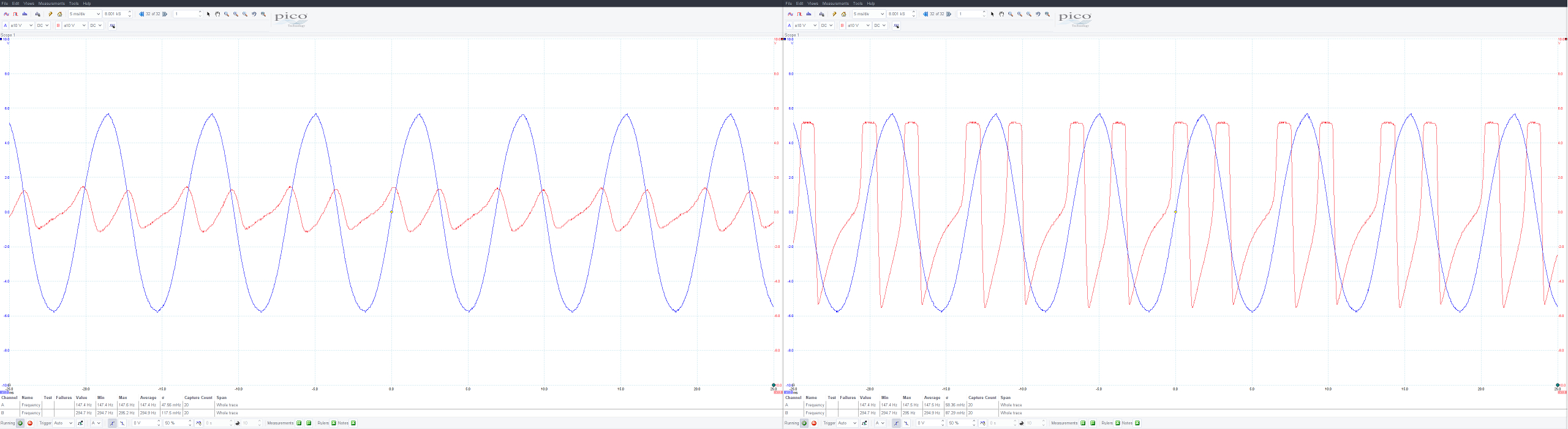
Tuning with an oscilloscope
Set up your oscilloscope so that you can monitor both the input (the base sine wave) and the output.
In the photos below, the blue signal is the sine wave input, and the red signal is the output of the Octave Fuzz.
First up, turn the Gain trimmer CCW until you can see only a little bit of clipping at the top of the sine wave. Your modules output should look similar to the picture below.
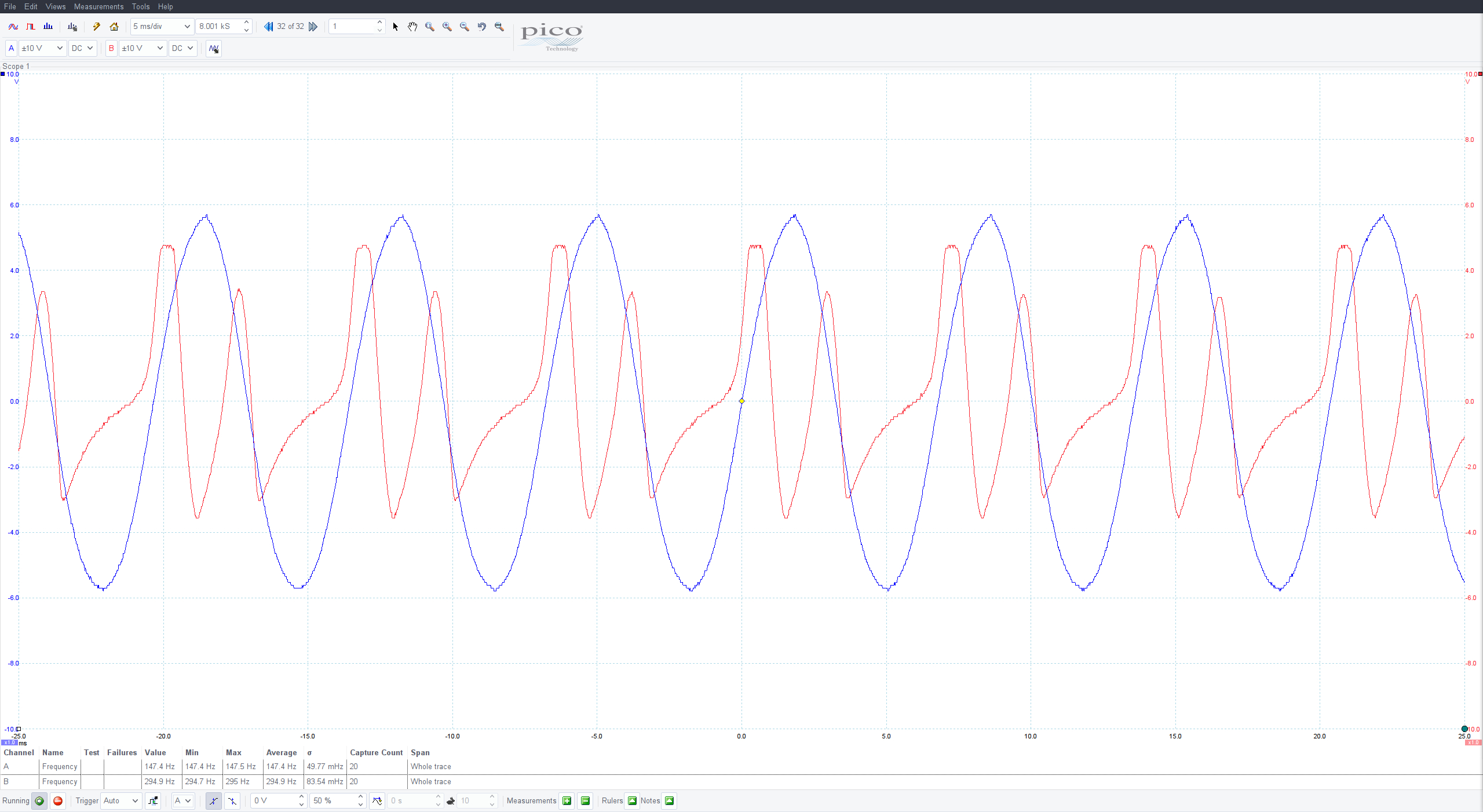 Next, we are going to adjust the frequency trimmer. This will balance out the two peaks that you see on the output of the Octave Fuzz. Turn the trimmer either CW or CCW until the two peaks on the output signal are about equal in terms of the max voltage that they hit.
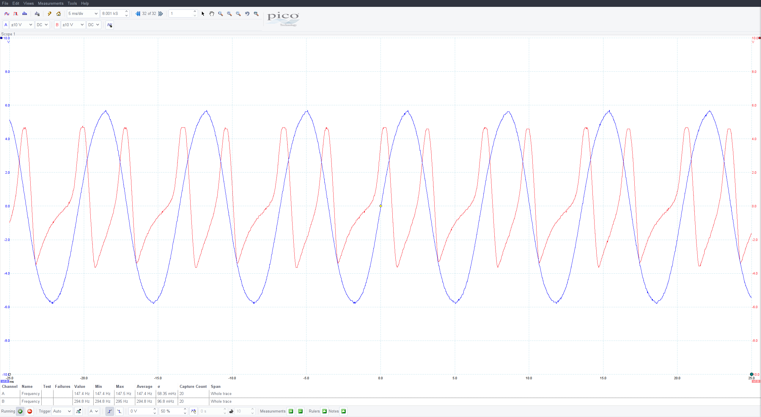 Next, sweep the EXPANDER knob back and forth from full CCW to full CW to make sure that you have a wide variety of sound variance. The below picture shows what the output of the Octave Fuzz looks like at full CCW (left) and full CW (right)