Important Links
Product Page
Store Page
Assembly Instructions
Bill of Materials
Quick Start Guide
Capacitor and Resistor Lookup Guide
Thank you for purchasing the Synthrotek Power Pak kit! This is an intermediate build. It is very important to get all the components properly soldered into the PCB in the correct placement. If you feel like you can handle it, please proceed! If not, get some help from a friend with experience or purchase a fully completed unit.
Please build according to the BOM, and not these instructions or the pictures alone. Some components may have changed since these were written, or we may not be able to get the proper components in the pictures.
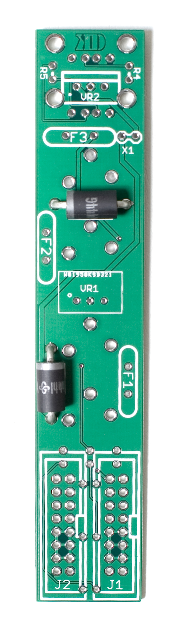
Diodes
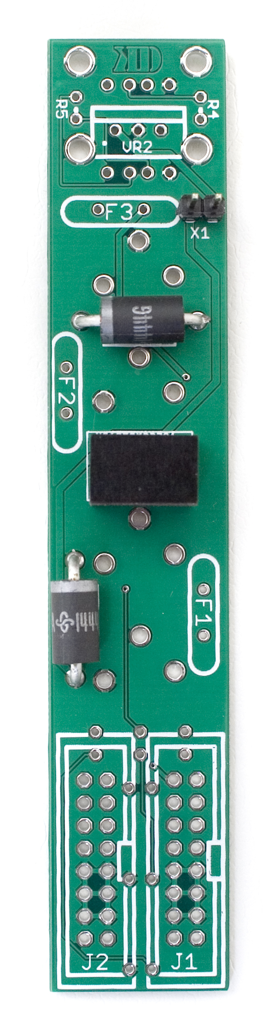
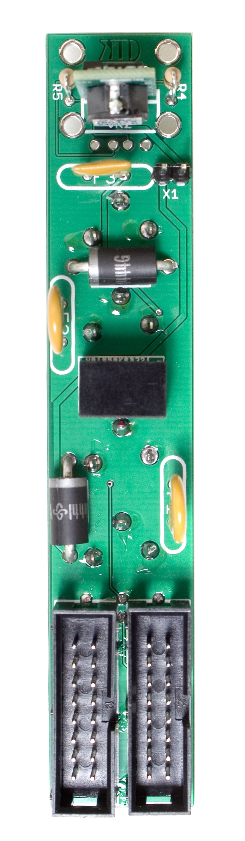
First thing we are going to populate is the diodes. Following the BOM, insert all the diodes into their proper spots, paying attention to the polarity. Diodes are polarized components, and must be populated correctly to function. Make sure to align the cathode stripe on the diode with the cathode marking on the silkscreen.
Then you can flip your project over onto a flat surface and solder all the diodes in place. Then clip the excess leads.
9v Regulator and 2 Pin Header
Now we are going to populate the 9v regulator and the 2 pin jumper header. If your case already has a 5v rail installed, or if you purchased the version of the kit WITHOUT the 5v regulator, you DO NOT need to populate the 2 Pin header.
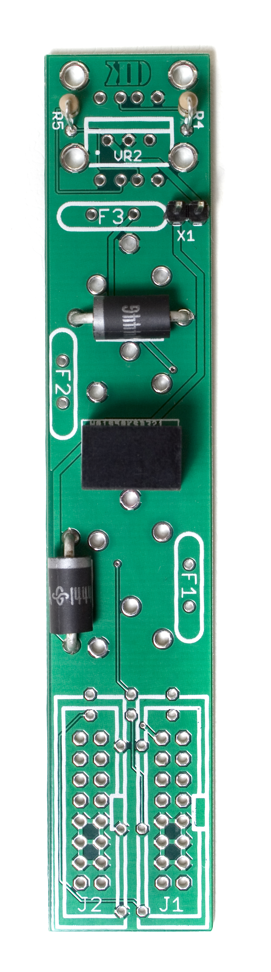
The 9v regulator has a dot on the side to mark pin 1, make sure when populating it that you match that dot to the dot on the PCB. (See photo below)
When you have everything oriented correctly, carefully flip your project over and solder everything in place, clipping any excess leads on the back.
Resistors
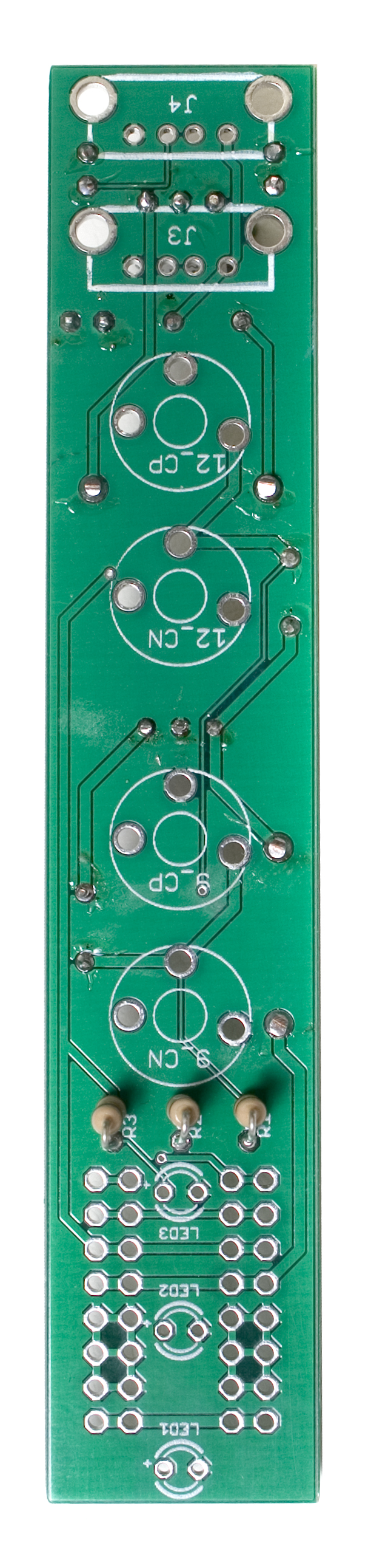
Next up are the resistors, which are not polarized so it doesn’t matter which way they are placed in, but it makes troubleshooting a lot easier if you line up all of the tolerance bands (usually a gold stripe) on the same side. Insert each resistor, matching the value to the proper spot as per the BOM. We are only populating the resistors on the back side of the board, as shown below.
Once they are all in there, carefully flip your project over and solder the resistors in place. Clip any excess leads.
Fuses
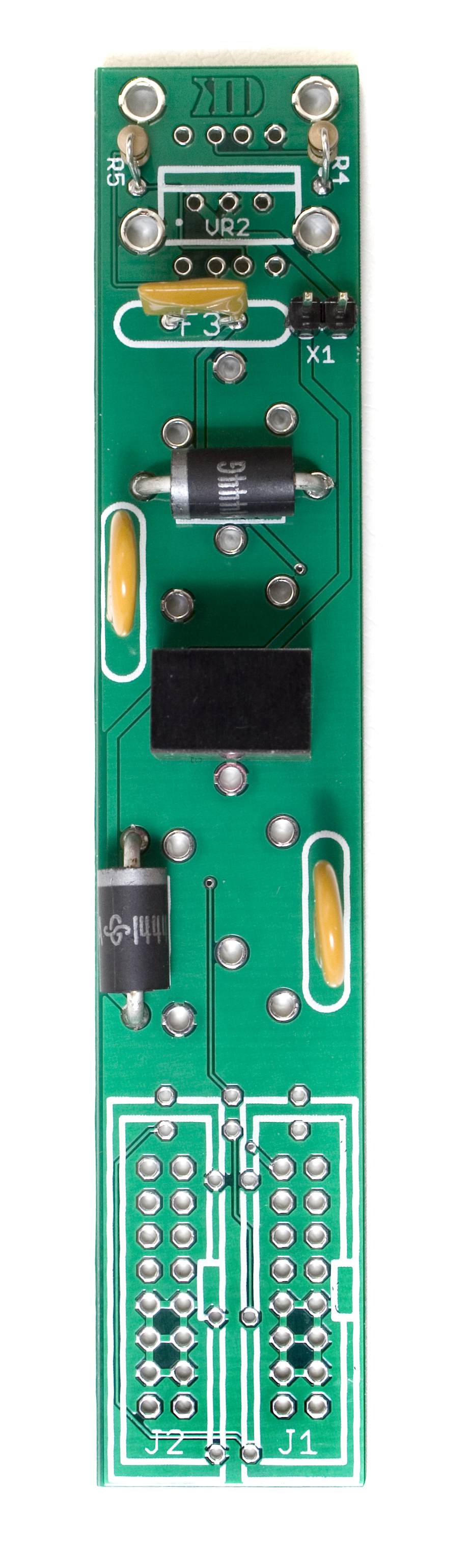
Next up are the three resettable fuses. These are non polarized, so it doesn’t matter which direction they are populated, but it makes any potential troubleshooting later easier if they are populated in a way that you can read them easily later.
Once you are sure they are in their correct spots, carefully flip the project over and solder them in place.
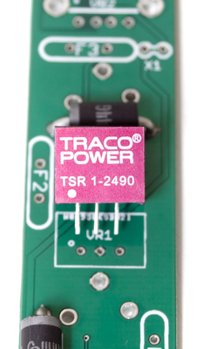
5v Regulator
Similar to the 2 pin header, if you already have 5v in your case, or you purchased the version of the kit without the 5v regulator, you can skip this step.
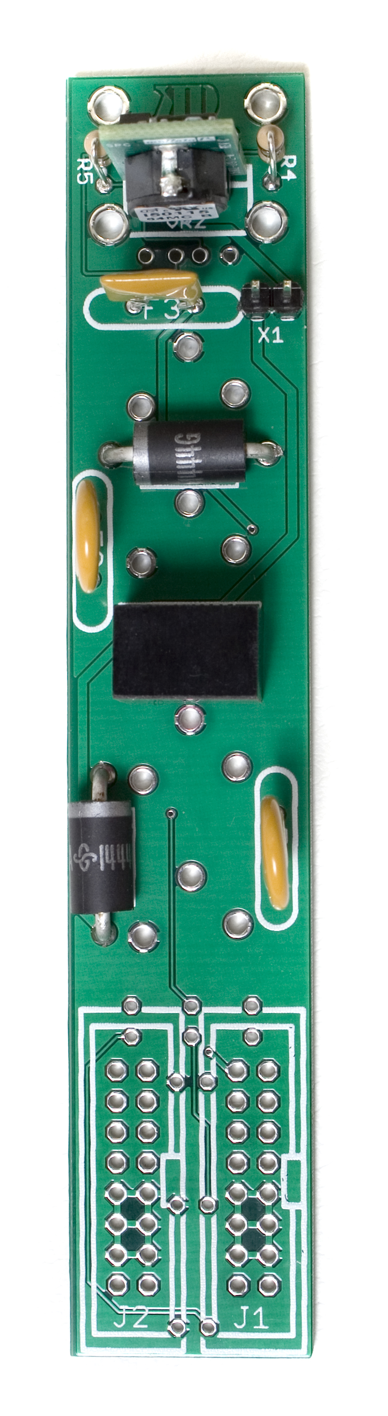
The 5v regulator is polarized, so when you are populating it, make sure to line up the vertical pcb part of it with the line on the PCB, and the side with the large black box facing towards the fuse, as shown below.
Once you have it in there, carefully flip your project over and solder it in place.
Resistors Part 2
Now we are going to work on the other side of the board for a little. Populate the resistors on the front of the board according to the bom. When you are sure you have them in the proper spots, carefully flip your project over and solder them in place.
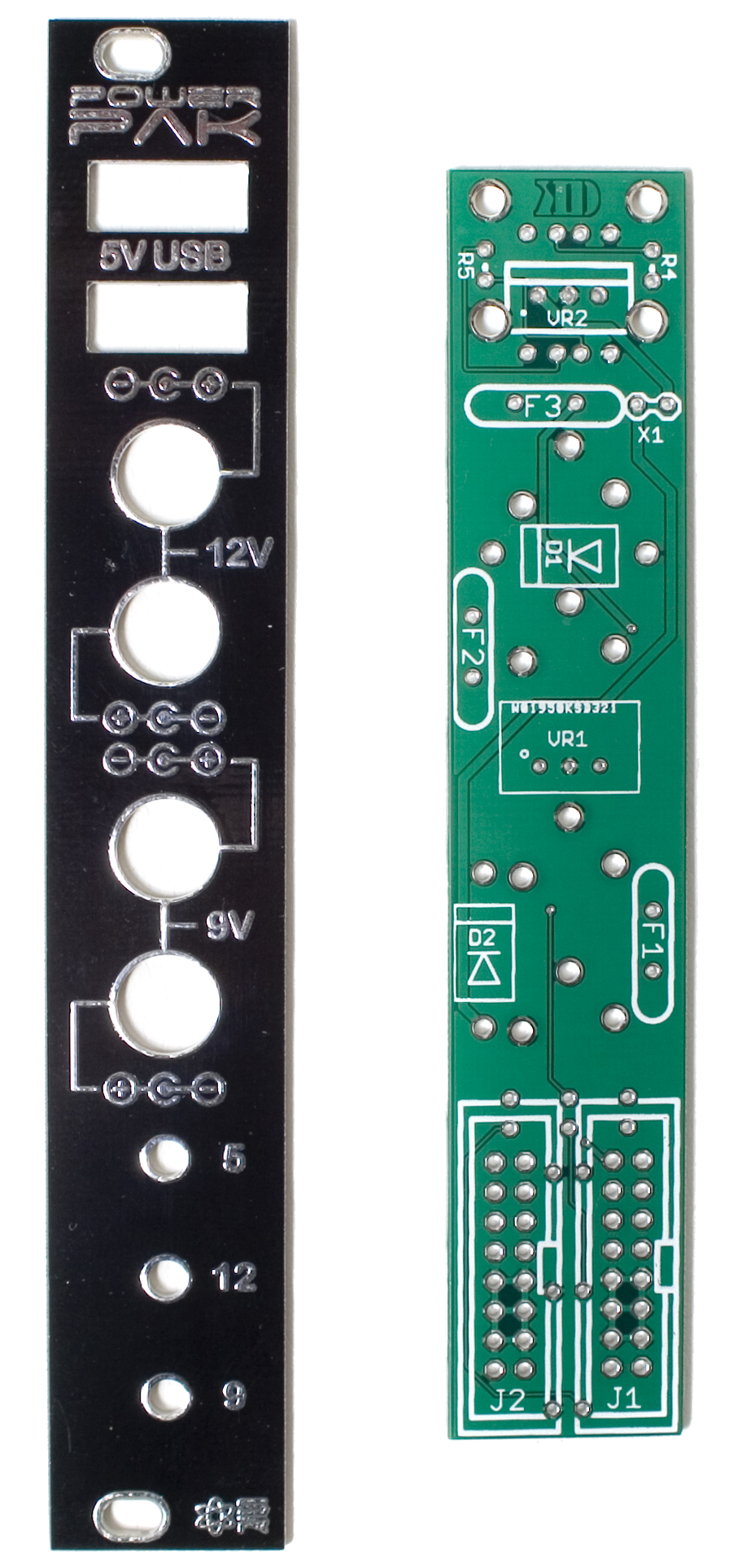
Front Panel Placement
Due to the size of this design, we will need to install the front panel temporarily to solder the LEDs in place, and then take it back off to finish soldering the power headers on the back side of the board.
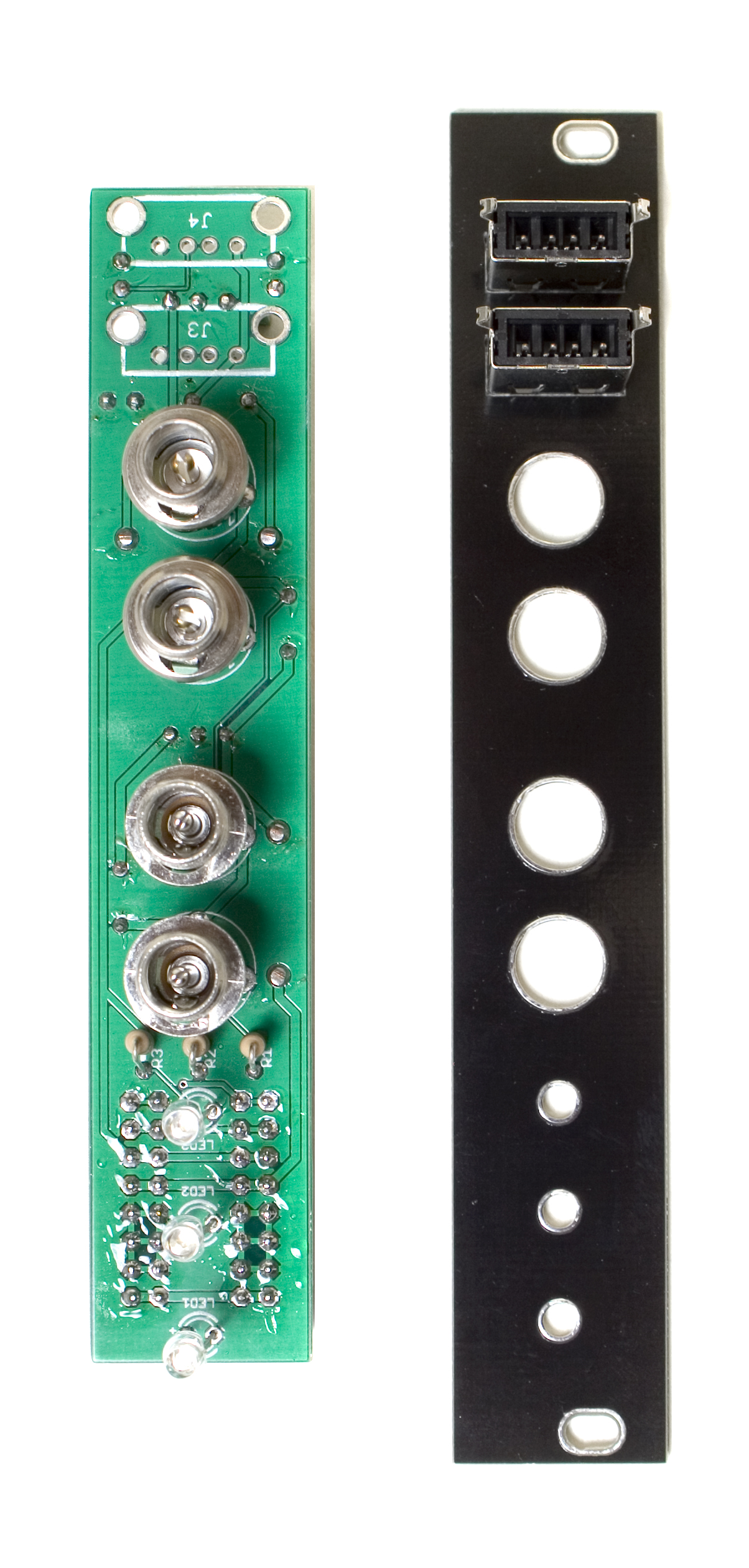
Go ahead and populate the 4 DC jacks, and the three LEDs, making sure to follow the BOM.
The LEDs are polarized, and care needs to be taken to ensure they are oriented properly. When populating them, insert the longer leg (anode) of the LED through the hole closer to the little ‘+’ symbol on the PCB.
Once everything is in place, set the front panel down over the top,
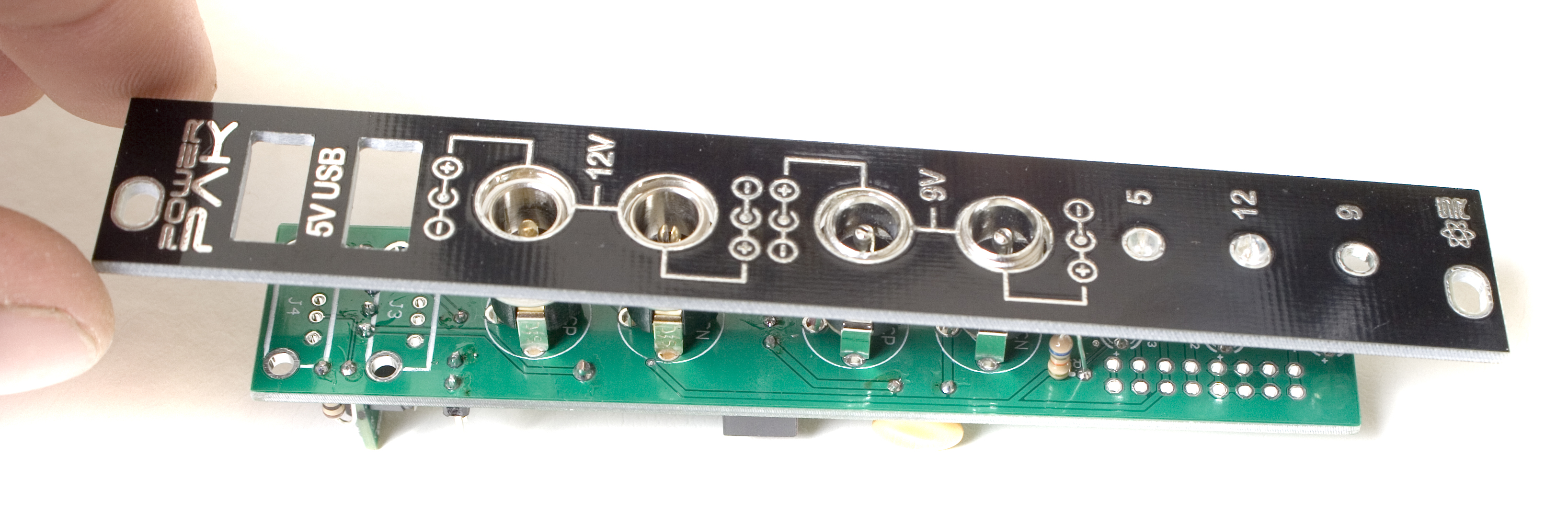
and tighten the dc jack nuts so that it holds the front panel in place.
When you flip the project over to solder everything, make sure that the LEDs are pushed up against the back side of the front panel fully, and that they are all even.
Also double check to make sure all the DC jacks are fully seated and the two boards are parallel.
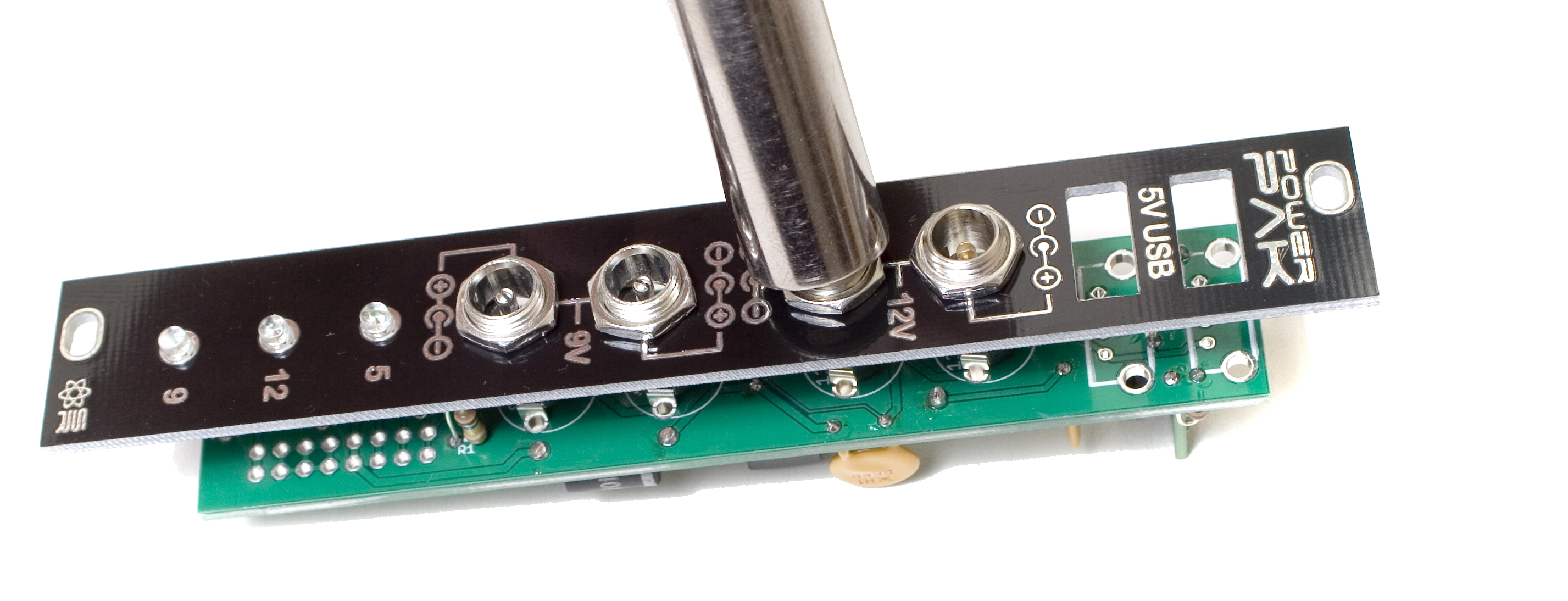
Once everything looks good, solder everything in place and clip the leads.
ATTN: Because the LEDs solder points are behind the power jacks (once installed) you will need to clip the leads as close to the PCB as possible. It is recommended to immediately reflow the solder points for the LEDs, just to ensure there aren’t any cold solder joints. You will not be able to get to them once the project is completed.
16 Pin Power Headers
Next, take the front panel back off by unscrewing the DC jack nuts, and carefully lift the front panel back off.
Now we can populate the two 16 pin power headers. These are located on the back side of the PCB. Make sure to align the notch in the headers with the notch indicator shown on the PCB.
Try to get them as flat as possible, but keep in mind it may not be possible to get them completely flat, due to the LED solder points. This is fine, as long as they aren’t sticking outside the dimensions of the PCB, or if they look like you may have a hard time plugging a power cable into them.
It is recommended to only solder one pin of the power headers, and then reheat the solder joint while moving it, so that it can be positioned more easily. Once you have everything lined up and looking good, go ahead and solder the rest of the pins on the header.
USB Jacks
Next up are the USB jacks on the front. Insert them into the front panel first, and then insert the front panel assembly into the PCB.
You will need to slightly bend the two case pins (the bent ones) on the USB jacks to get them through the front panel, and then bend them back out (once in) so that they fit into the PCB.
Once you have everything fully seated, go ahead and put the nuts back on the DC jacks, and make sure everything is nice and flat. Once it looks good, carefully flip your project over and solder the USB jacks into place.
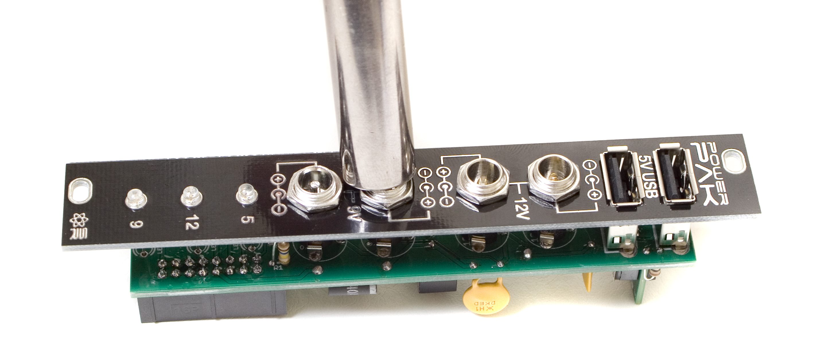
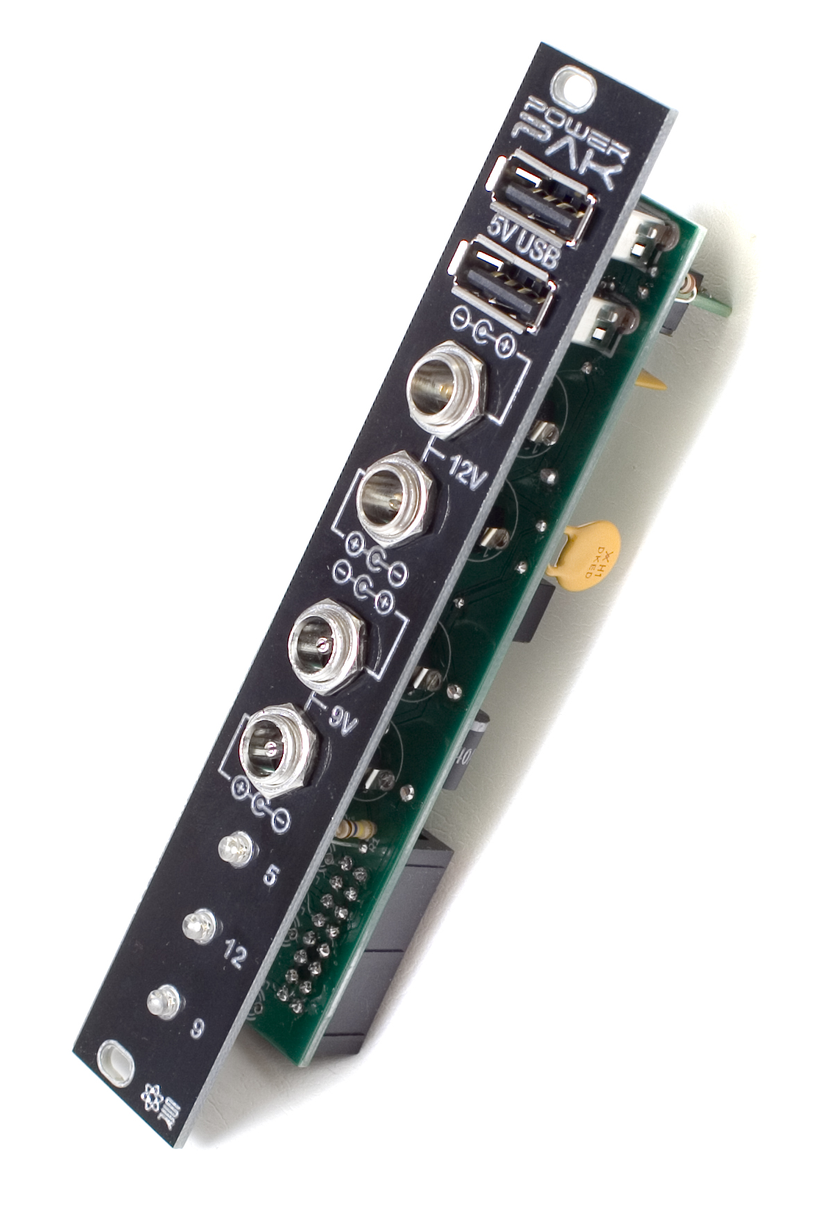
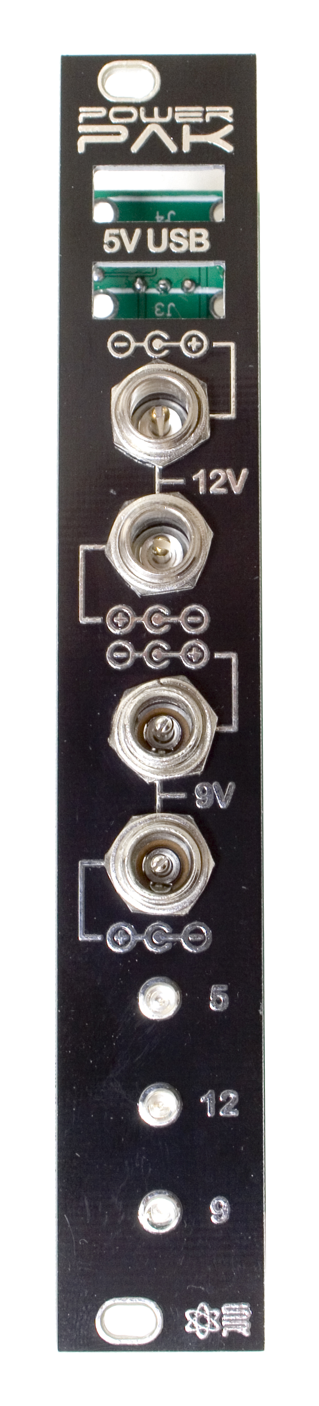
Completed Unit
Congratulations! You just finished building the Synthrotek Power Pak!
Please keep in mind that because this product is similar to a power supply, and can possibly draw a lot of current, you MUST use both of the power connectors on the back, with two separate power cables.