


Important Links
Product Page
Store Page
Assembly Instructions
Bill of Materials
Capacitor and Resistor Lookup Guide
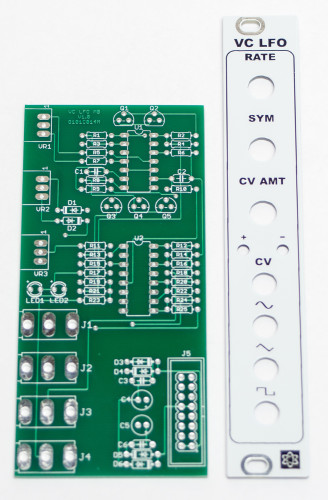
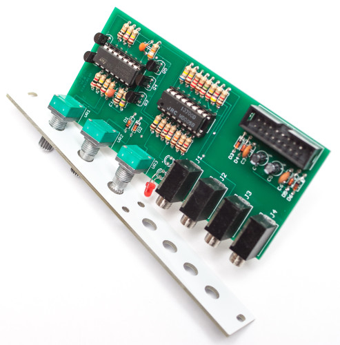
MST VC LFO PANEL & PCB
Thank you for purchasing the MST Voltage Controlled Low Frequency Oscillator Eurorack module kit! This is an intermediate build. If you feel like you can handle it please proceed! If not, get some help from a friend with experience or purchase a fully completed unit.
ATTN: Please follow the BOM and these instructions and don’t populate from the PCB alone. Also sometimes we cannot get the exact pictured components, so please look over your parts and check the codes first. Lets begin!
DIODES
Start with the diodes as shown below, then turn over on a firm surface to solder, then clip your leads. Diodes are polarized components so you must match the black stripe on your diodes with the white stripe on the PCB silkscreen.
MST VC LFO DIODES
RESISTORS
Populate first, then turn over on a firm surface to solder and clip leads. Using a flat rigid card or another PCB can help hold the resistors in place as you turn the board over.
MST VC LFO RESISTORS
SOCKETS
Place the IC Sockets by aligning the notch with the notch graphic on the PCB Silk Screen. Turn over on a flat surface and solder into place.
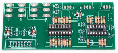
MST VC LFO SOCKETS
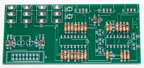
TRANSISTORS & CAPACITORS
Add the ceramic capacitors and the transistors by matching the flat side of the transistors with the flat side on the silk screen, turn over to solder and clip leads. Next, make sure you orient the electrolytic capacitors in correctly. The longer lead needs to be inserted into the hole that has the “+” marking near it. Solder and clip leads.
MST VC LFO TRANSISTORS & CAPACITORS
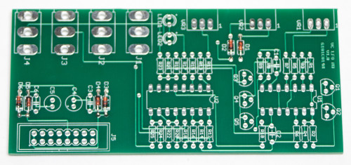
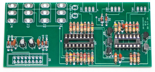
INTEGRATED CIRCUITS & 16-PIN POWER HEADER
Place the ICs in place by aligning the notch with the notch graphic on the PCB Silk Screen and notch on the sockets. Next add the 16-Pin Eurorack Power Connector in place by matching the key notch with the key indicator on the PCB silk screen. Turn over on a firm flat surface and carefully solder all of the pins.
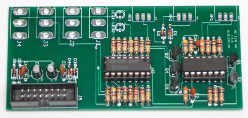
MST 16-Pin Shrouded Power Connector and IC’s
JACKS & POTENTIOMETERS
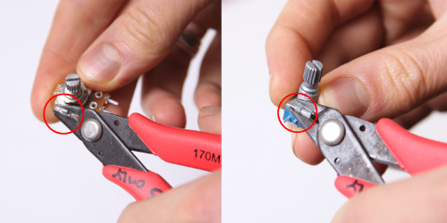
Don’t forget to cut the nubs on the potentiometers as necessary.
After trimming the nubs on your pots (if they are present), place the pots in the board first, turn the board over with the pots in place, and then solder ONLY THE CENTER PIN to the PCB. Do likewise for the jacks now. Place the the jacks in and on a flat surface ONLY THE CENTER PIN to the PCB.
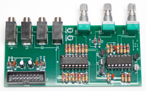
MST VC LFO JACKS & POTS
Now carefully bend the RED LED as shown below.
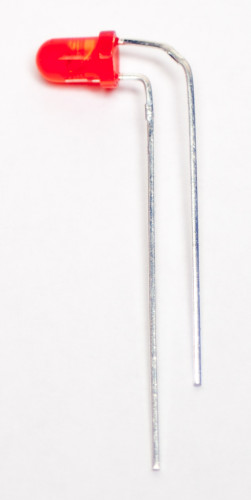
Proper Bend for RED LED
Place the RED LED in place as shown below (the shorter lead will orient with the flat side on the LED graphic). DO NOT SOLDER JUST YET! Now place the panel on and over the jacks and pots as shown below.
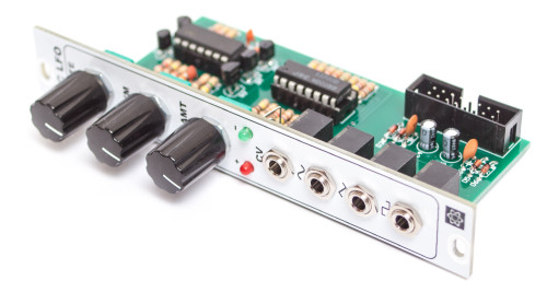
MST VC LFO PANEL PLACEMENT
Tighten down the nuts on the jacks and pots and place in the green LED as shown below (take time to bend the LED leads first). Also push through the red LED in place.
MST VC LFO GREEN LED BEND
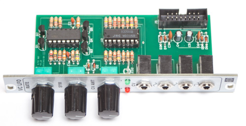
MST VC LFO Panel Finalization
MAKE SURE the PCB is perpendicular to the panel and also that the jacks and pots are flush to the PCB. You heat up the one soldered center pin to make sure this is case. Once everything is flush finalize the soldering by soldering in the LEDs, Jacks and POTS. Trim leads that may protrude past the plane of the panel as to not interfere with other modules.
Congrats! You are done with your build and ready for testing. Thank you for choosing Synthrotek!
I built one of these, and I’m getting some strange behavior. The diodes at the power input are getting hot, as are both chips. If I take the IC’s out, the diodes stop getting hot. I’ve tried replacing the IC’s, no dice. Thoughts?
wierd, it seems liek I’m getting +12v on both the positive and negative pins of the 074. hmmmm
Hey Bill,
If you are getting +12v on both pins on your 074, this would explain the issue of your diodes getting hot. The reason they don’t get hot when you take out the ICs, is because you’ve opened the circuit and there is no longer the same flow of current as before.
Double check with a multi-meter that your +12 and -12 are not shorted to each other on your board. And double check that there are no other power shorts. Also double check that your power supply is properly outputting +!2v and -12v,
If you are still having issues after going over these things, feel free to send some pictures/video of the module to sales@synthrotek.com. I’ll be able to take a closer look and maybe we can figure this out!
Thanks
-Zach
I don’t get continuity between +12 and -12, so it doesn’t appear shorted. I also don’t get continuity from the 074 pins to the power rails as far as I can tell. The power supply looks fine, my other modules run ok and my ST power module shows all rails are active. I’ll shoot you some pics of the board.
My first thought would be to check the input power rectifier diode polarity. Sounds like one or two may be backward.
Can film caps be used for the 100n & 10n caps?
Yes! Some people have said it changes the sound but I haven’t personally done it.
But yes, the module should still work!
-Zach
Hello, I finished building one of these today but it does not seem to oscillate. The red led is always shining when powered and it looks like I’m not getting anything from the outputs…
What do i need to check ? What voltages should I get at control pins ?
Thanks in advance,
Hi.
Which component would I have change to use this as a VCO with a smaller audio range and finer tuning?
Thanks for your answer.
Kind regards,
Ludwig.
Hi Ludwig, you would be looking at a lot of changes to make that happen. Probably easier to just get a DIY VCO.