


Important Links
Product Page
Store Page
Assembly Instructions
Bill of Materials
Capacitor and Resistor Lookup Guide
FACE THE FUZZ WIRED VERSION
ASSEMBLY INSTRUCTIONS
Hello, and thank you for purchasing the Face the Fuzz Wired DIY Kit! This page will walk you through how to build your kit and fit it into a Hammond style 1590BB case.
Let’s Begin!
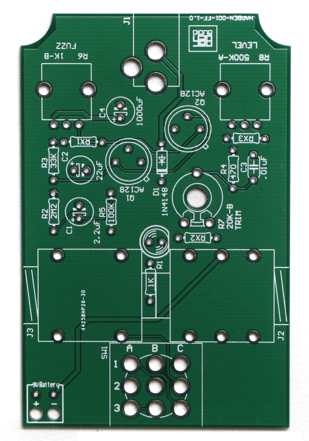
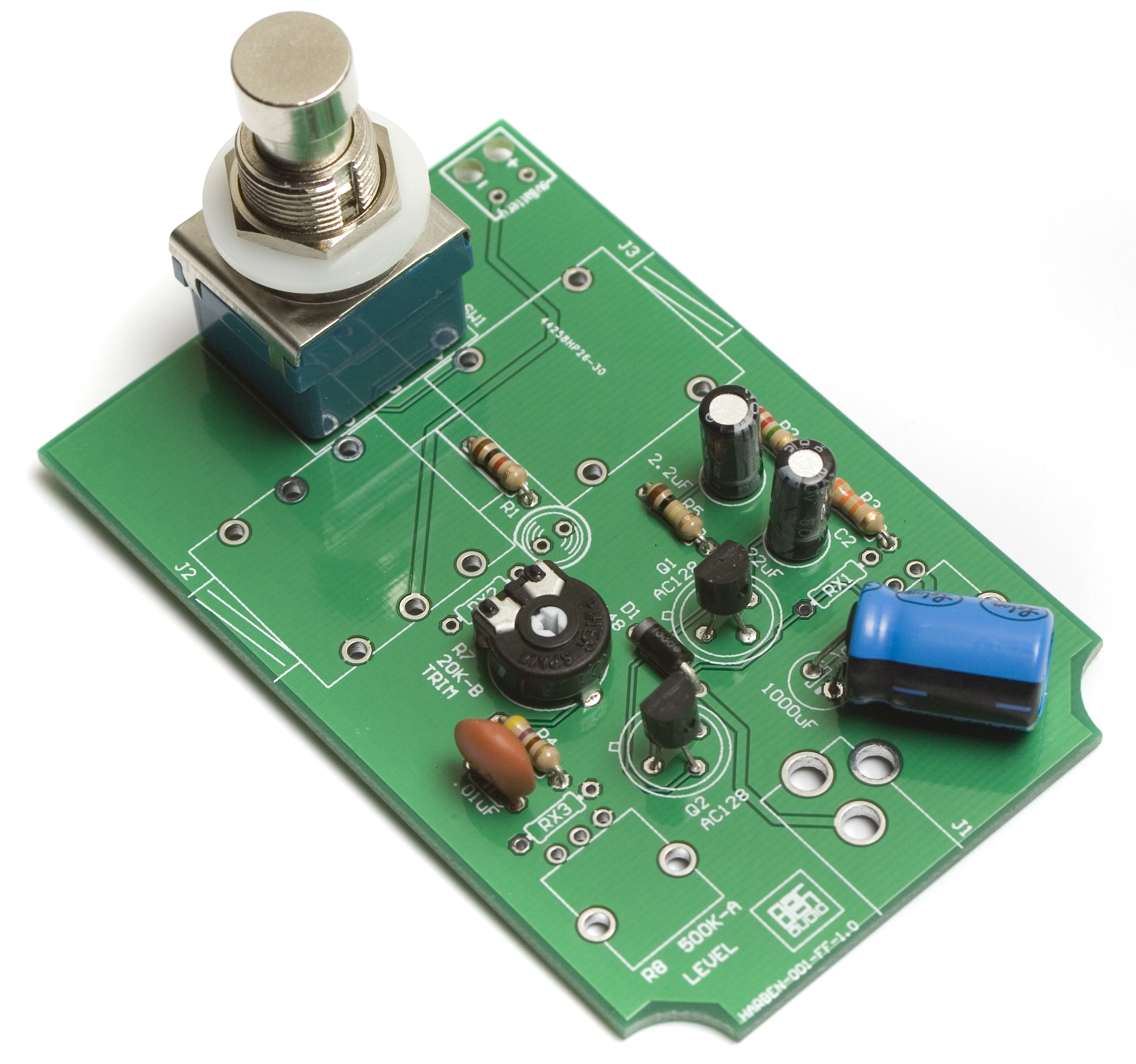
Face the Fuzz PCB
Resistors and Diode
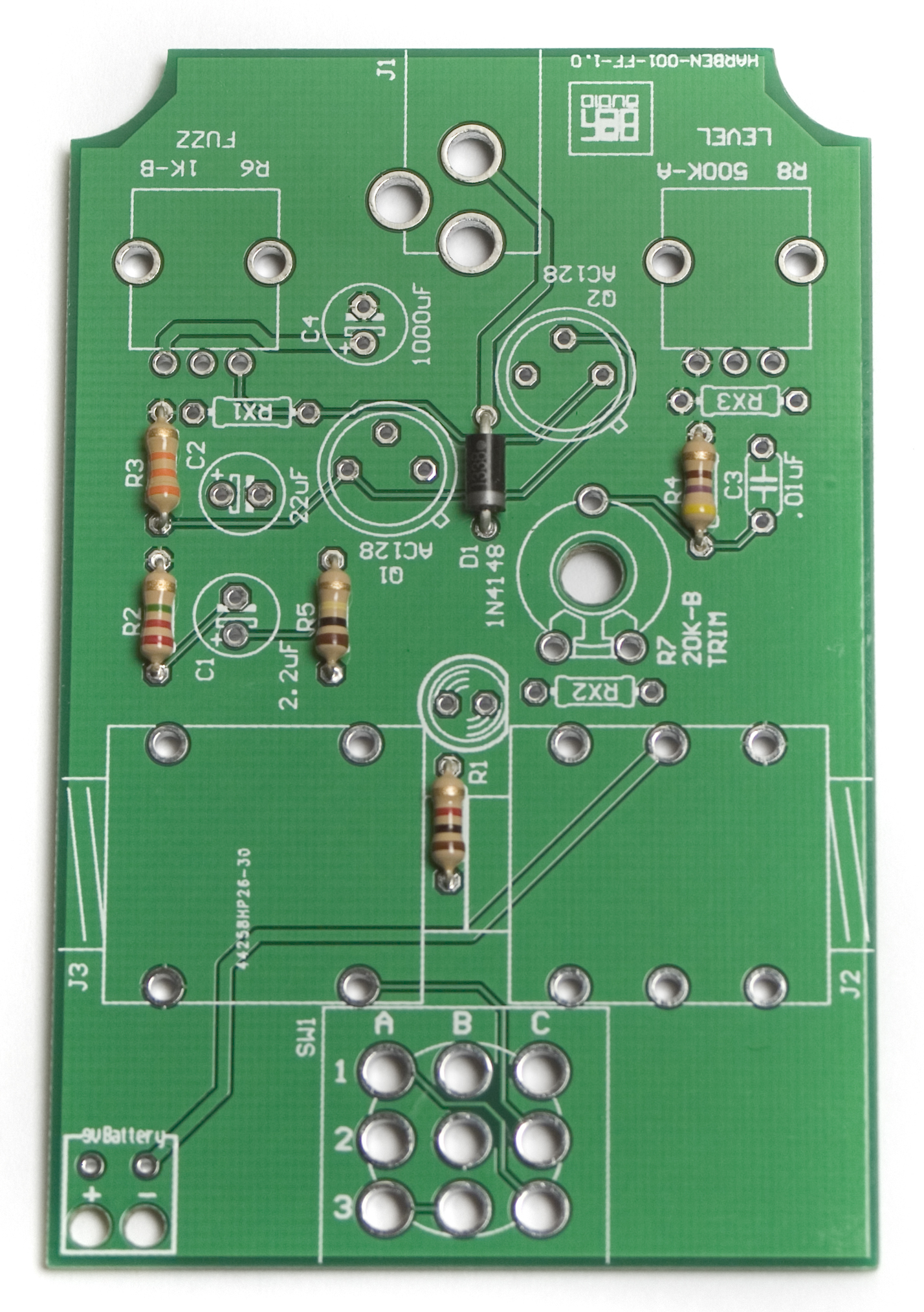
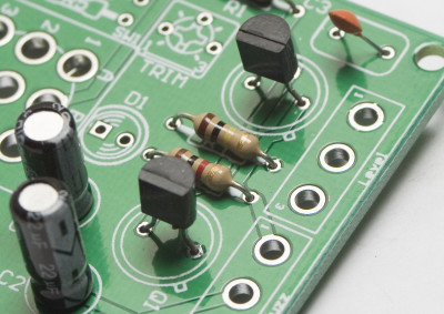
Face the Fuzz Resistors and Diode
First up are the resistors and Diode. Insert the resistors into their proper places according to the BOM. Then insert the Diode into place with the stripe on the diode facing the same way as the stripe on the board. Diodes are polarized components and will not work if installed improperly. Afterwards, flip your project over carefully onto a flat surface and solder everything in place. Then clip your leads.
Trimmer Potentiometer
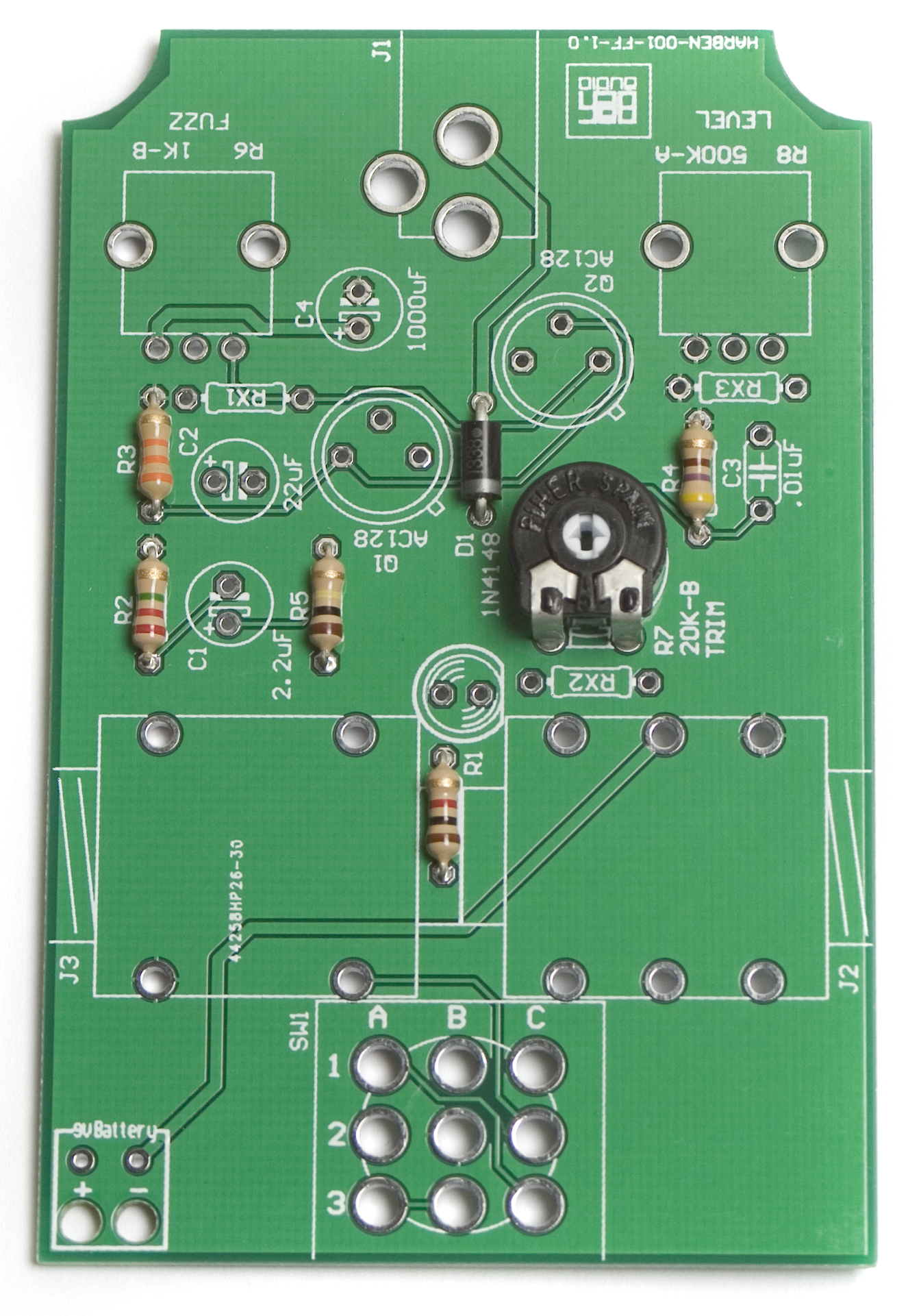
Next up is the trimmer potentiometer. Insert it into the designated spot on the silkscreen, with the two legs that are closer together towards the side of the board with the stomp switch. Now you can flip the board over, solder and clip the leads (if necessary)
Transistors
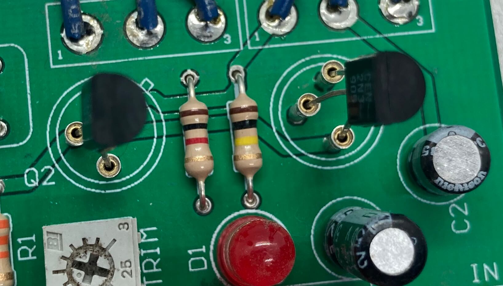
2N3905 Transistor Orientation
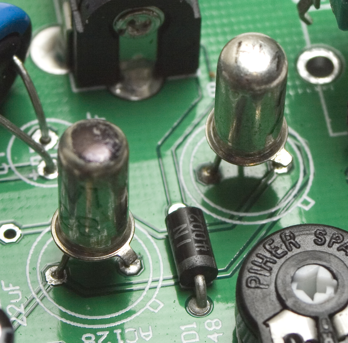
Face the Fuzz Germanium Transistor placement
FOR OLDER KITS ONLY!!
BC558 PNP Transistor Orientation
Pay special attention when placing the transistors onto the PCB. Each of the three leads has a specific function and the circuit will not work if they are placed incorrectly.
When using the silicon 2N3905 or BC558 transistors, follow the orientation in their respective photos. With the 2N3905, the ROUNDED side of the transistor should should face the tab on the silkscreen. With the BC558, the FLAT side of the transistor should face the tab on the silkscreen.
Germanium transistors: Line up the little tab on the transistor with the tab on the board as shown in the first picture above. Q1 gets the lower gain transistor (if you are using Synthrotek’s transistors, it will be marked with a black dot). Q2 gets the higher gain transistor.
Capacitors
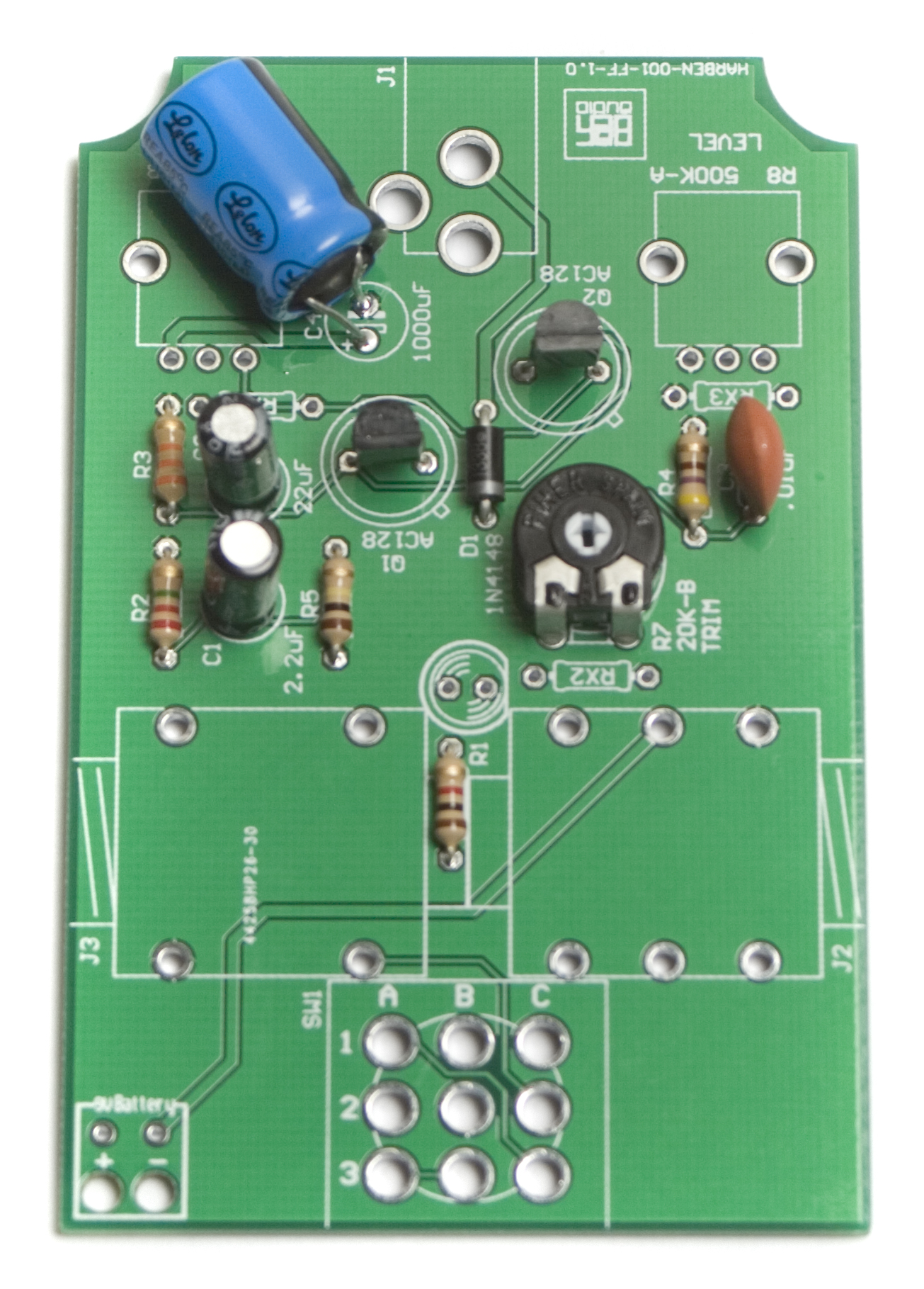
Face the Fuzz Capacitors
Now we can populate the capacitors into the board according to the BOM. Electrolytic capacitors are polarized, so make sure when placing them, that the stripe on the capacitor goes into the hole opposite from the one marked with a ‘+’ symbol. The 1000uF capacitor needs to be laid on its side, as in the photo above for it to fit inside the case. It is easiest to insert it into the holes, then push it over on its side at a diagonal so that it lays flat. Once you have populated all the capacitors, flip it over and solder them, clipping the leads afterwards.
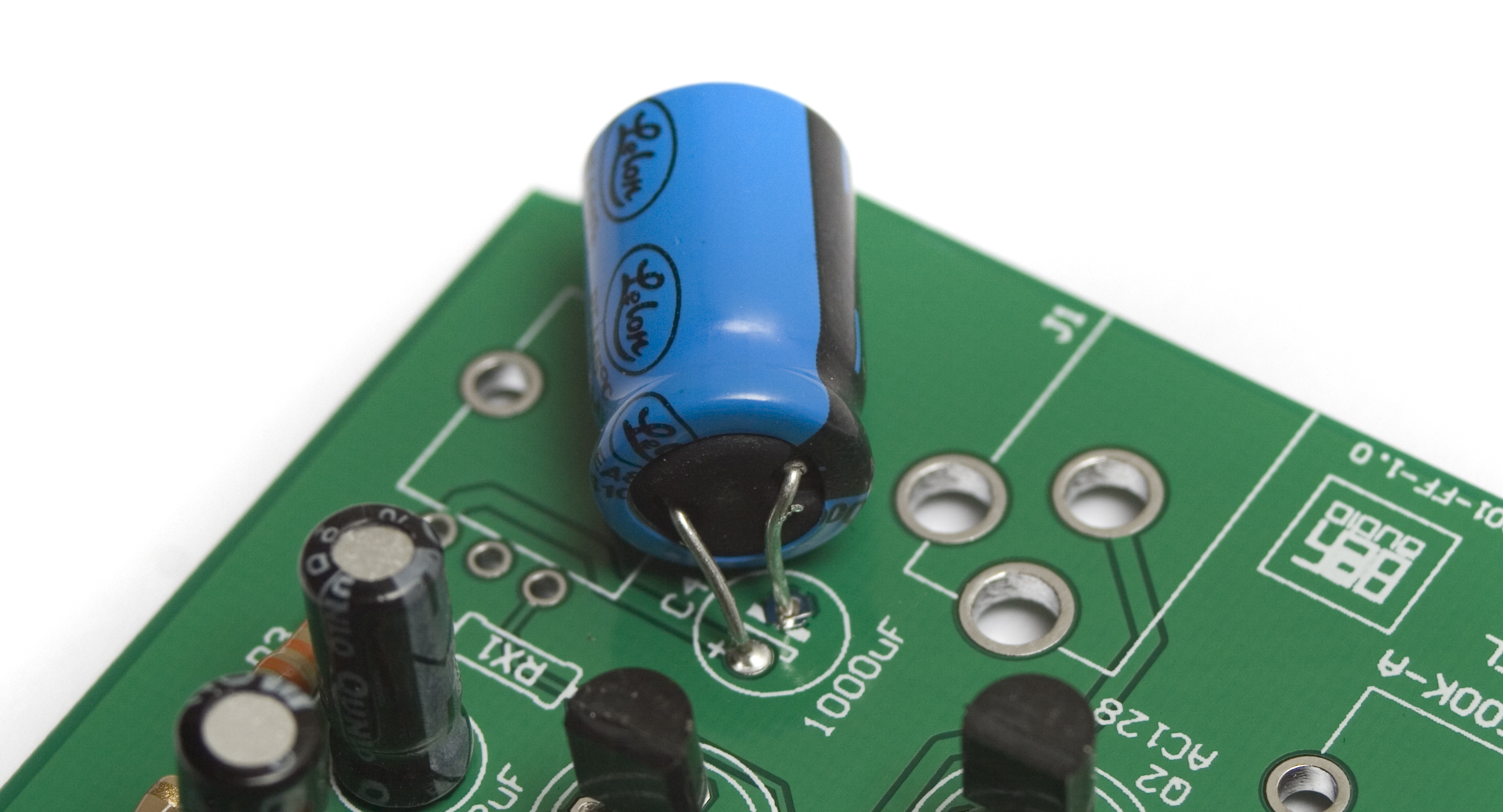
Face the Fuzz Large Cap Closeup
3PDT Stomp Switch
Face the Fuzz Stomp Switch
Next up is the stomp switch. Insert it into the designated spot, with the flat sides of the switch facing the ‘front’ and ‘back’ of the board, as shown in the picture above. Then flip over onto a flat surface and solder in place. I would recommend only soldering one leg of the switch at first, then checking alignment before finishing the soldering, as de-soldering one of these is VERY difficult without damage to the board.
Wiring the Components
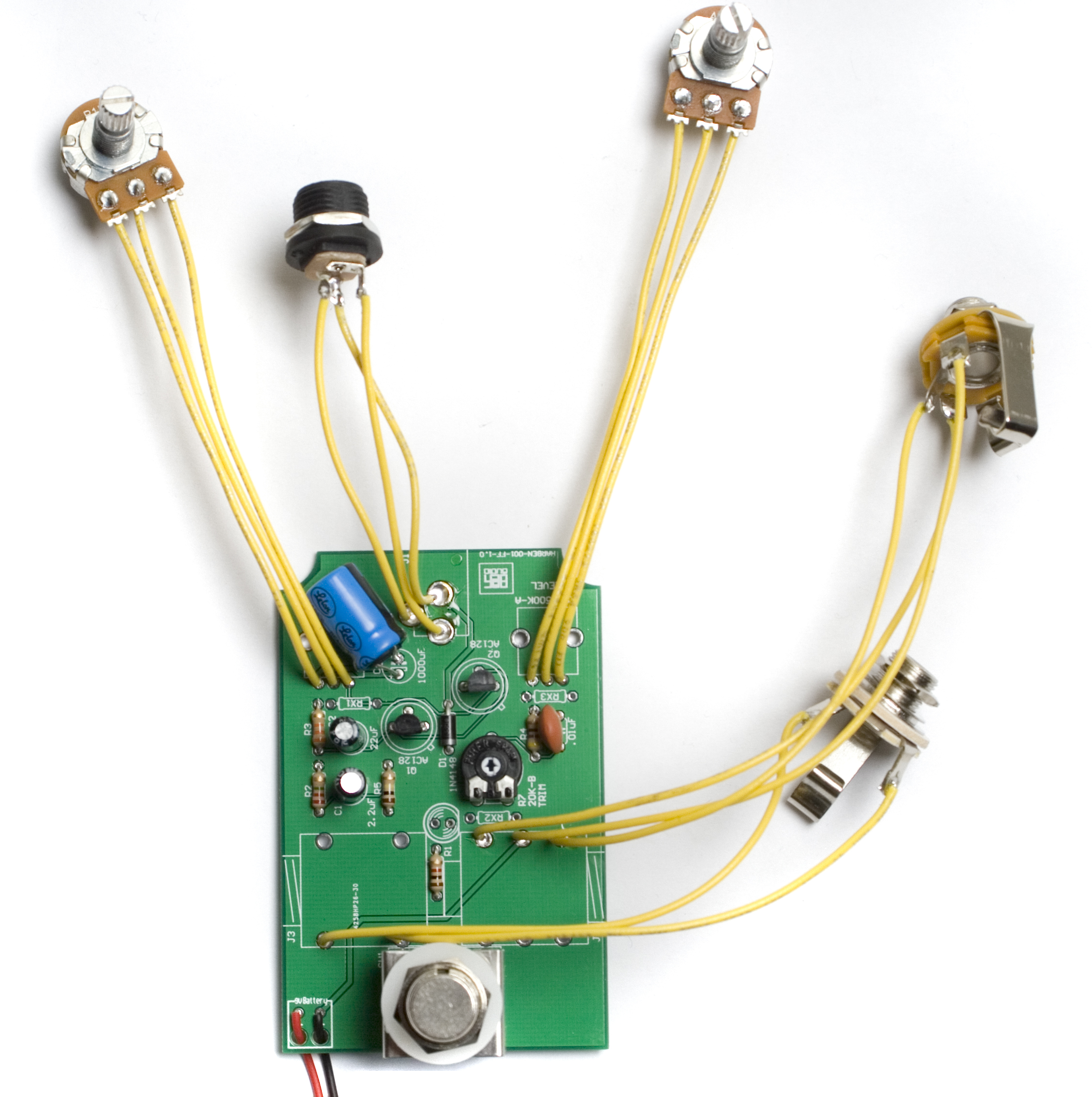
Next we will be soldering all the wired components to the board. This first thing to do is to solder lengths of wire to the components.
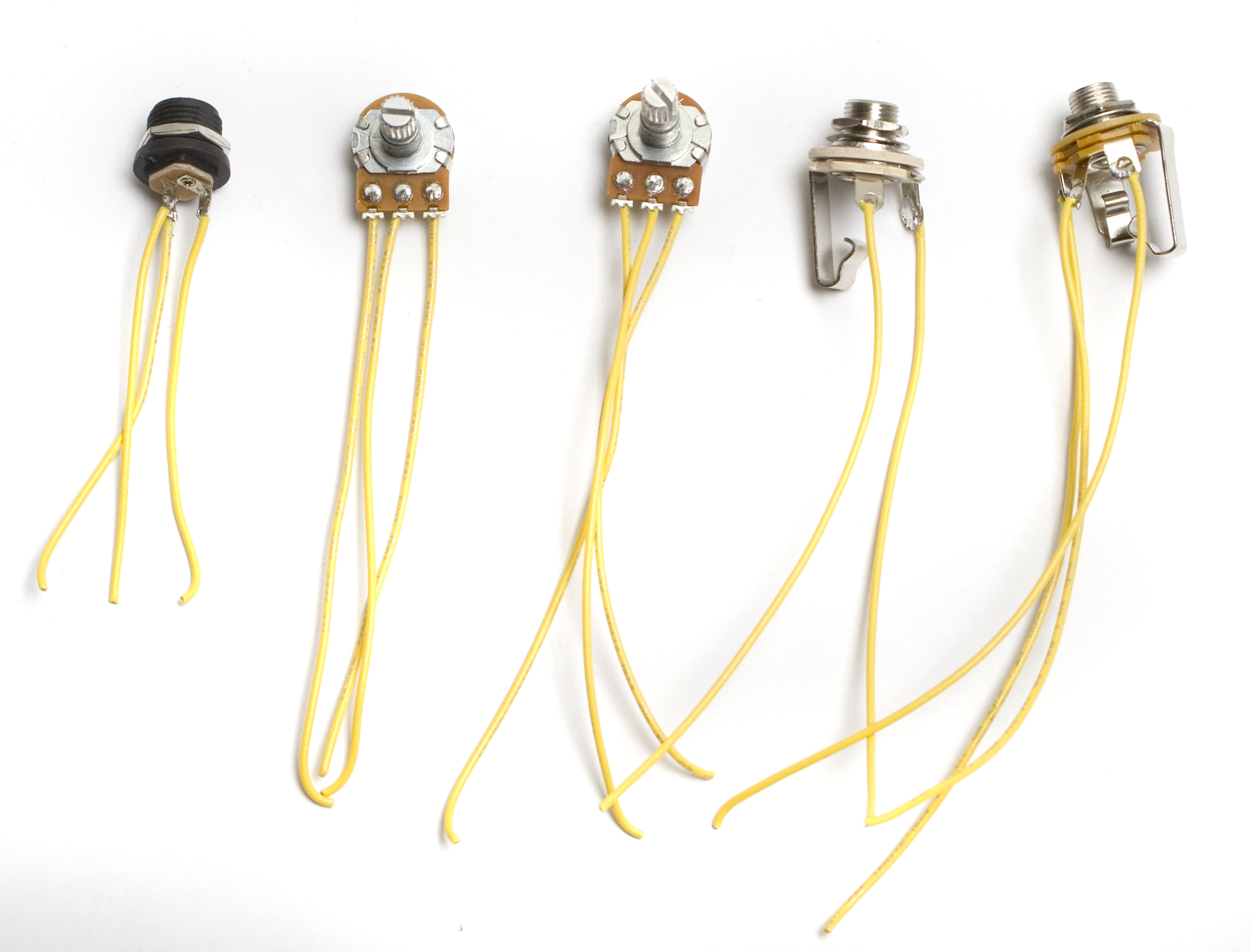
Face the Fuzz Components wired
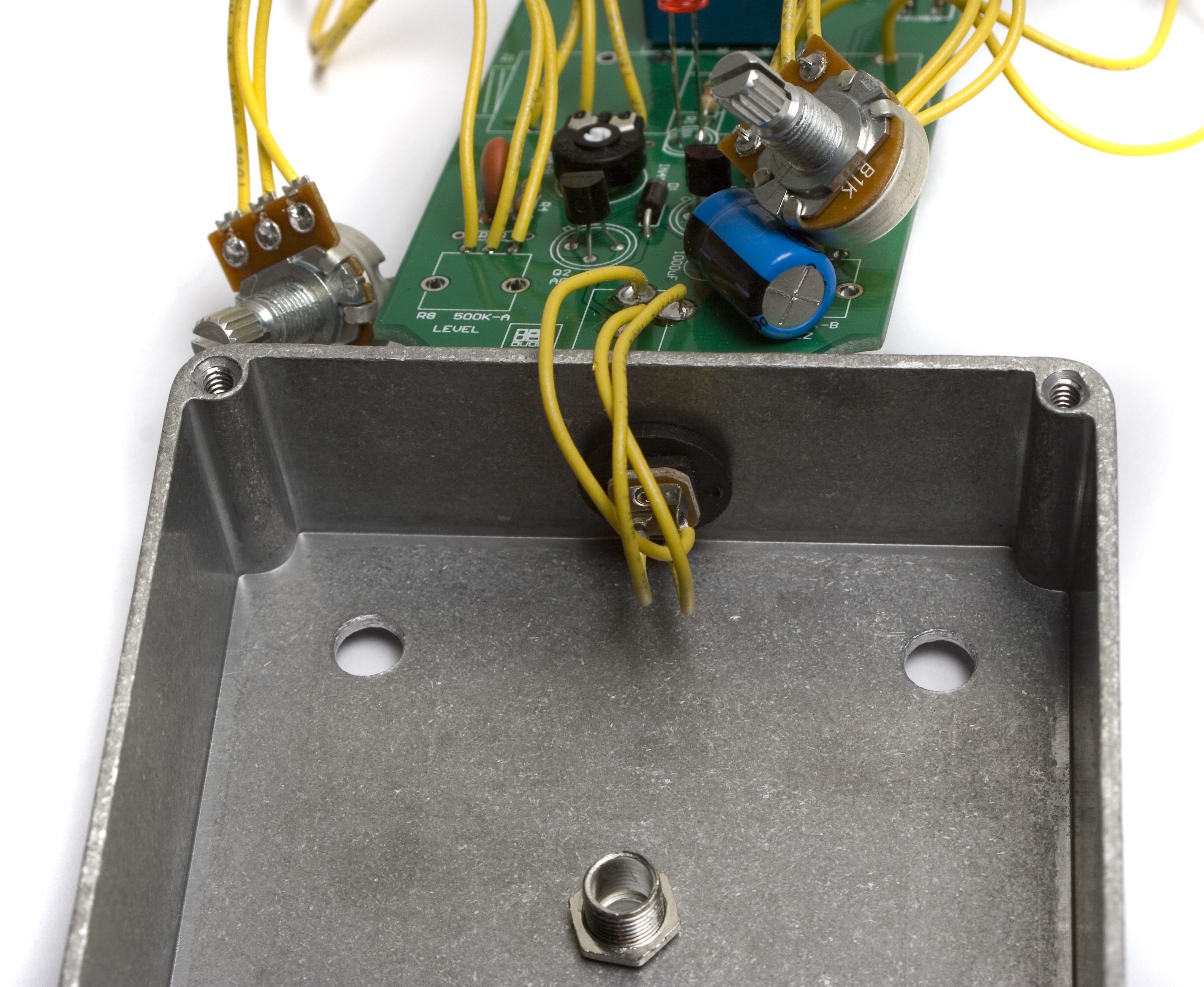
Input / Output Jacks
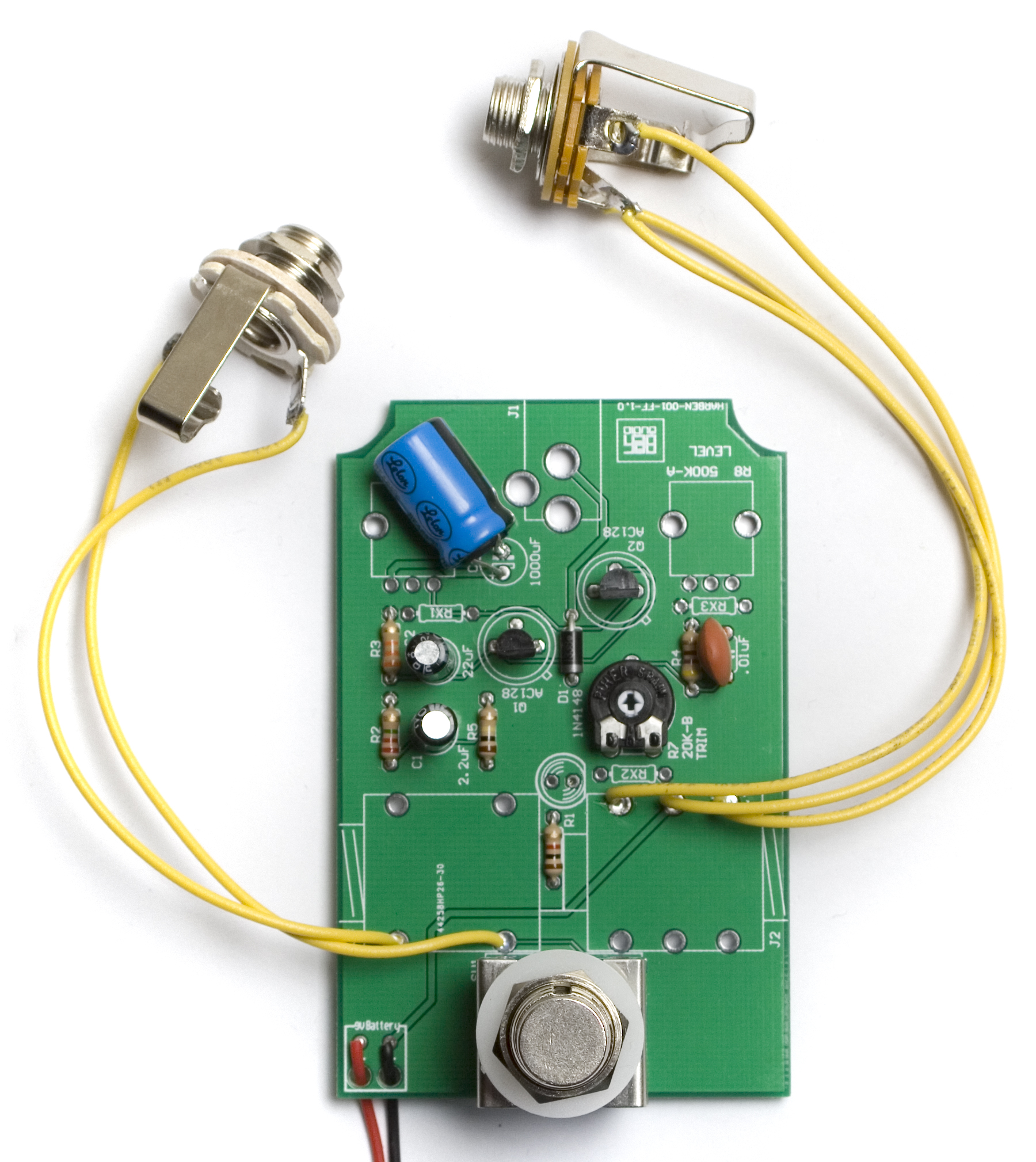
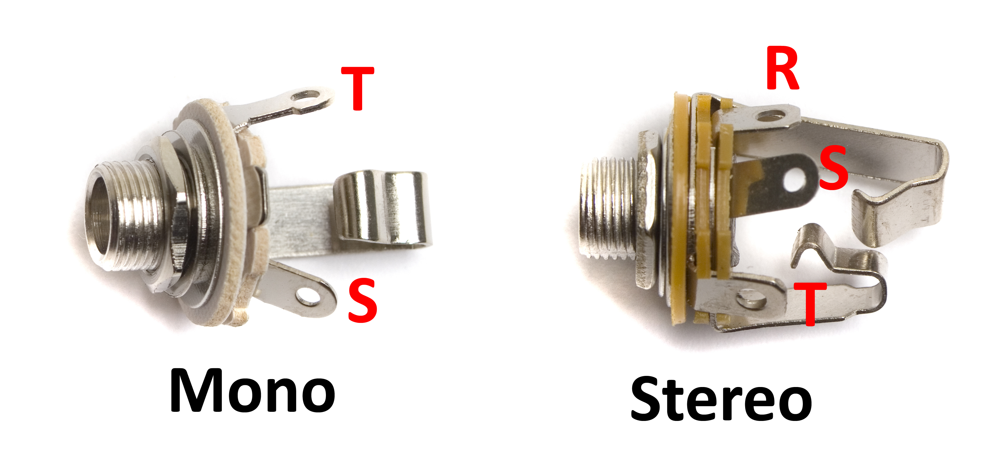
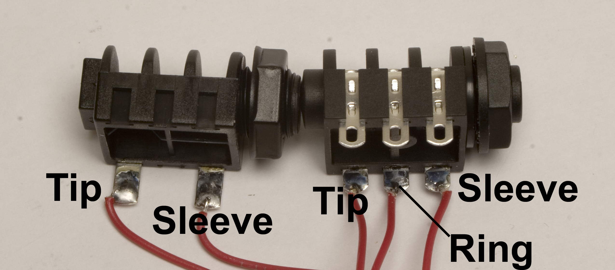
Face the Fuzz Wired Jacks
When Soldering the input and output jacks to the board, make sure to use the proper solder points on the PCB. For the Stereo Jack, use the three closest to the trimmer pot, and for the mono jack, use the two closer to the stomp switch.
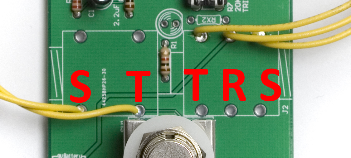
Use these two pictures to double check that you are wiring the jacks up properly. If you instead got plastic jacks, see the very bottom picture.
Potentiometer Wiring
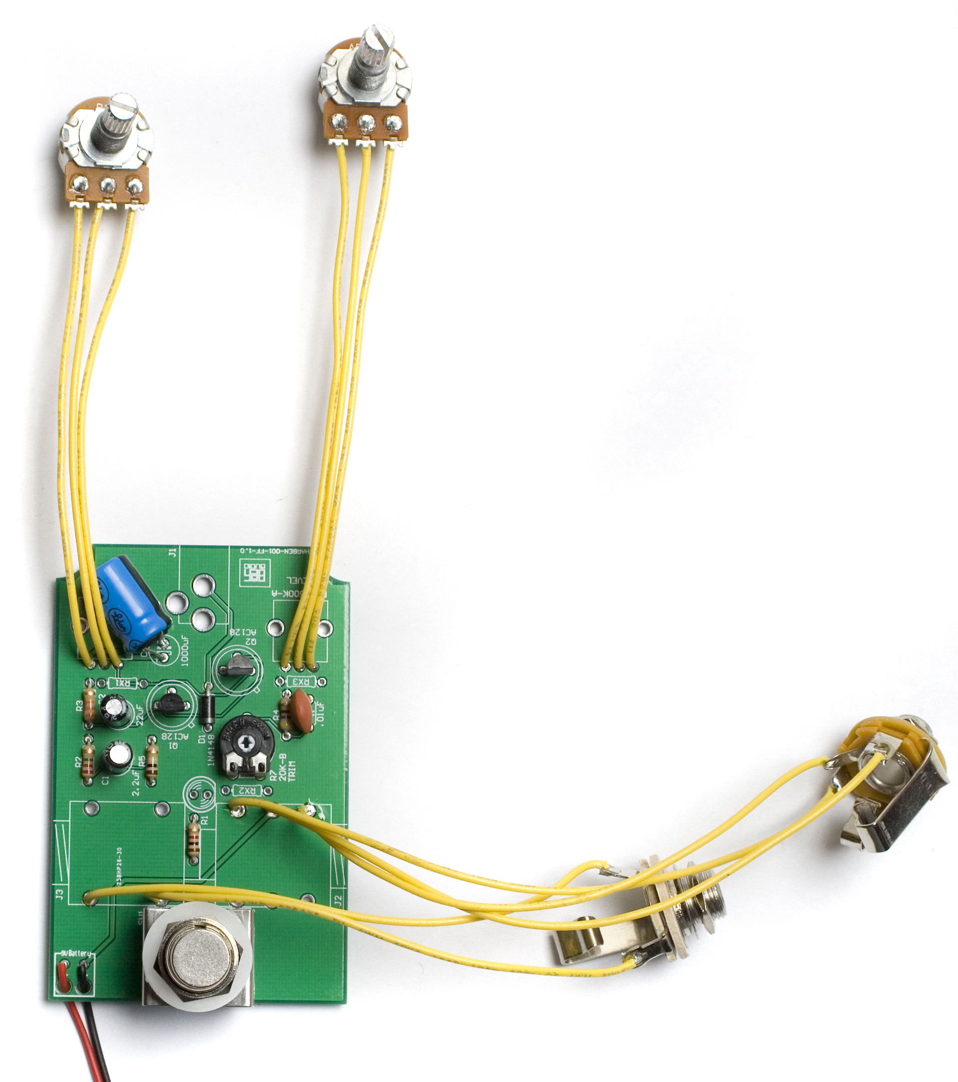
Face the Fuzz Potentiometer Wiring
Next solder the potentiometer wires to the PCB, making sure to get them in the proper order, as per the following picture, or they will not work right.
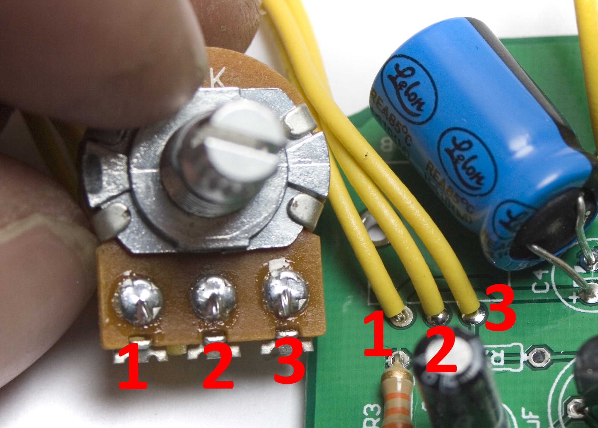
Face the Fuzz Pot Numbering
The numbering is the same on both sides of the board.
DC Jack Wiring
Face the Fuzz DC Jack Wiring
Now we can solder the DC jack wires into their respective holes. This can be a little tricky, so double check all wires before soldering.
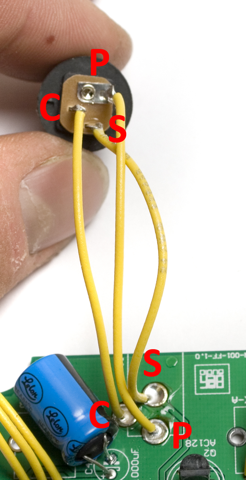
Face the Fuzz DC Jack Pinout
Enclosure Prep
We are now ready to prep the enclosure for the pedal.
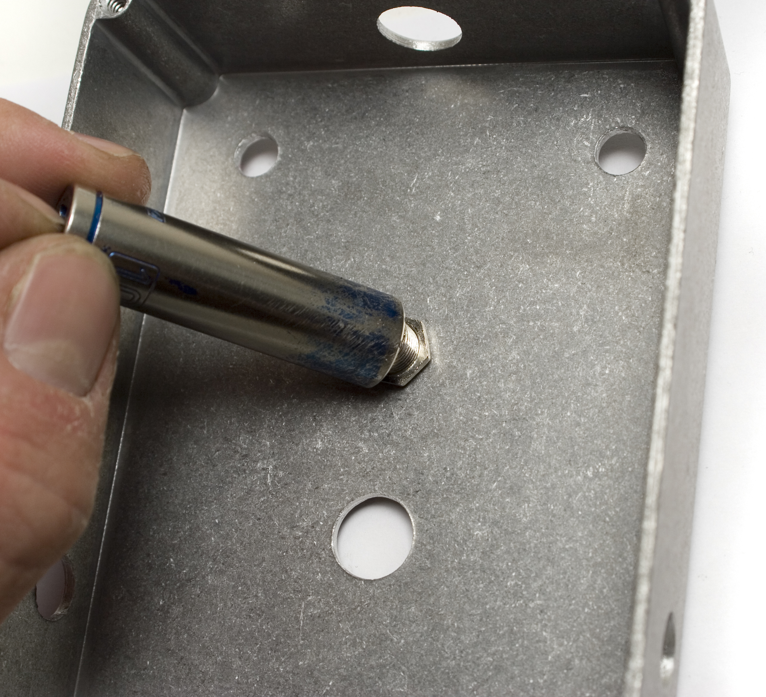
Insert the LED Bezel through the case, and tighten the nut down from the back until snug. Do not over tighten, or something may be damaged.
LED Placement
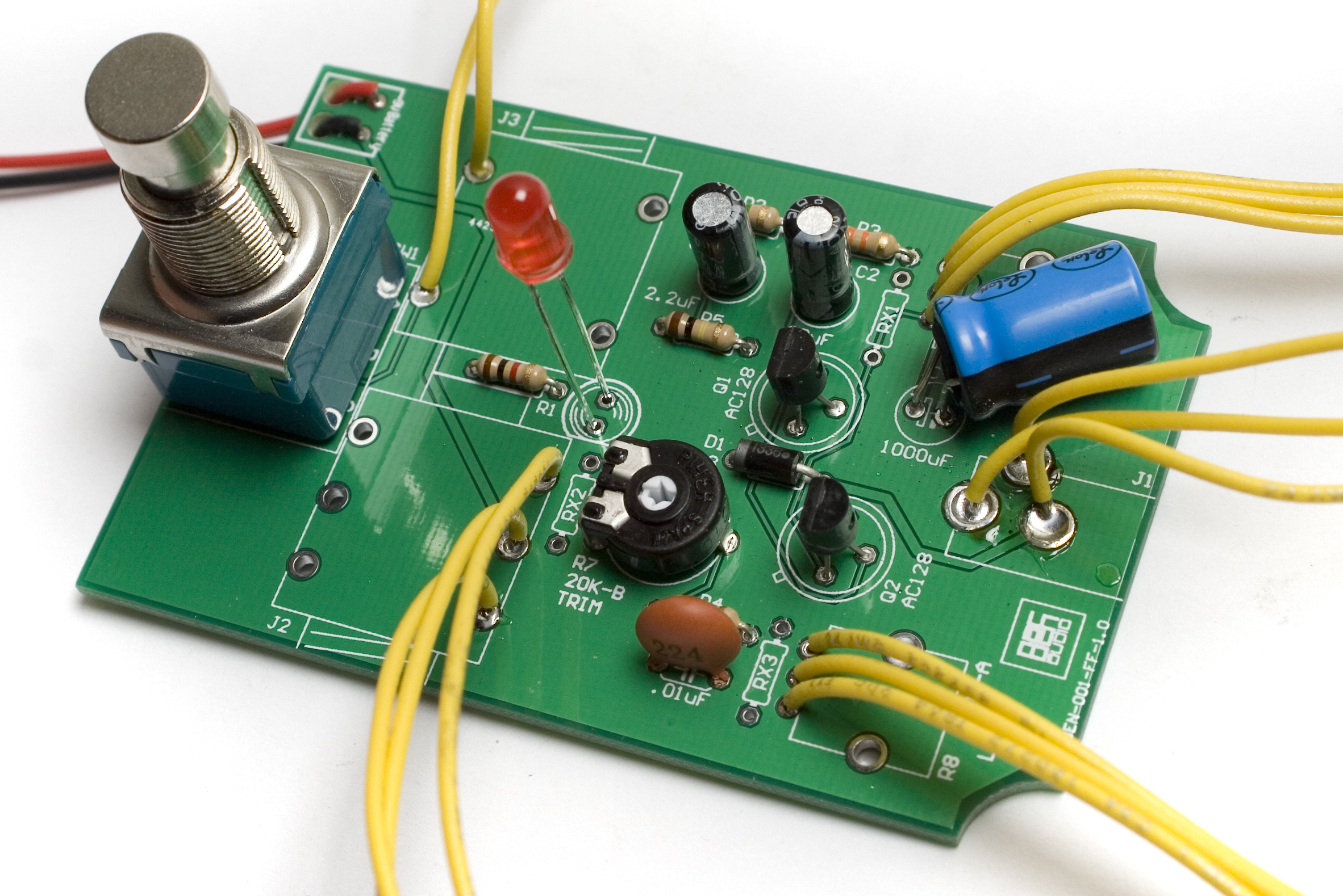
Face the Fuzz LED Placement
Next, insert the LED into the board, with the shorter leg (cathode) facing the side of the silkscreen that has a flat edge. The LED will also have a flat edge on it to help line it up. DO NOT solder it yet, we need to get the height right first.
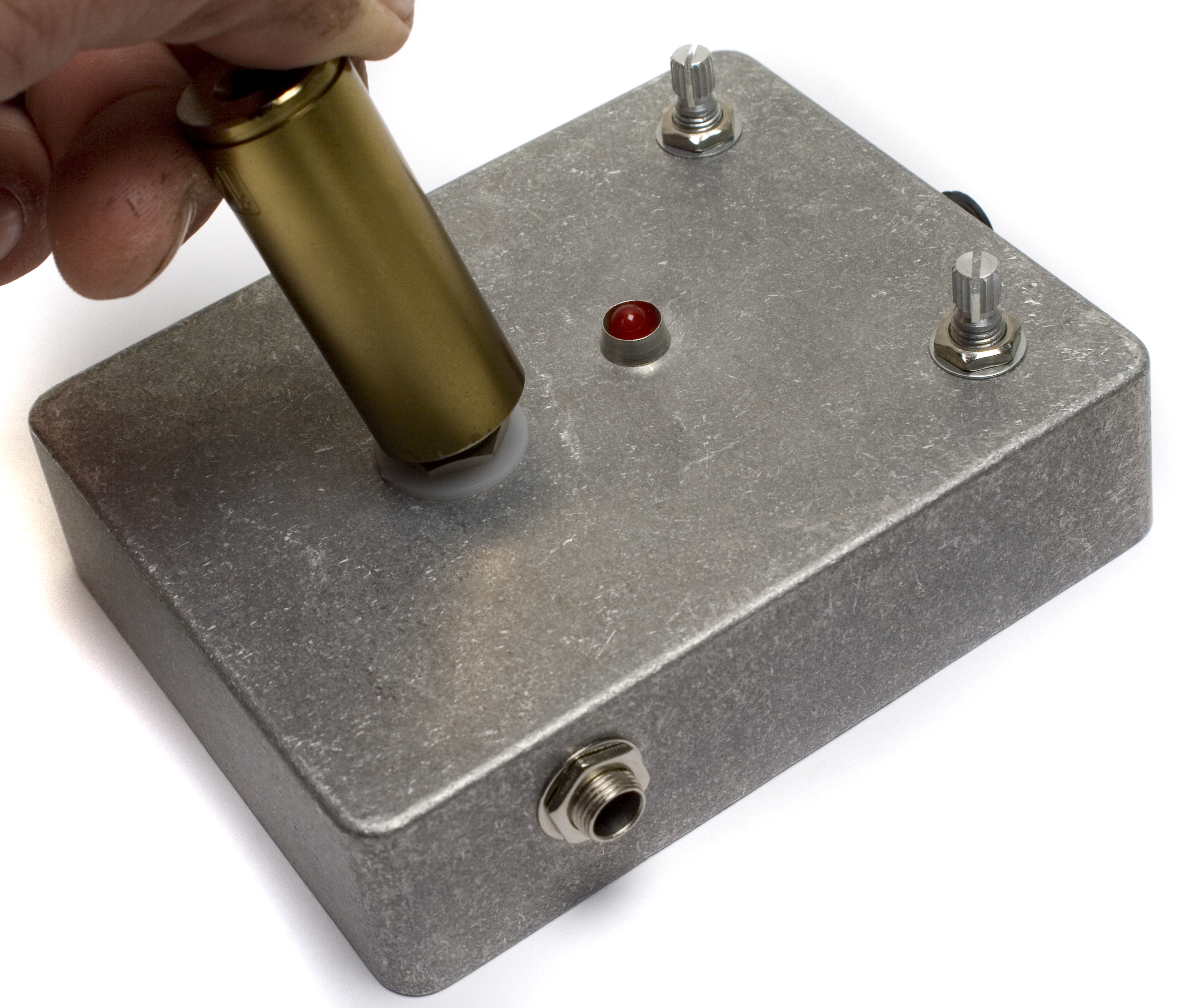
Enclosure Test Fit
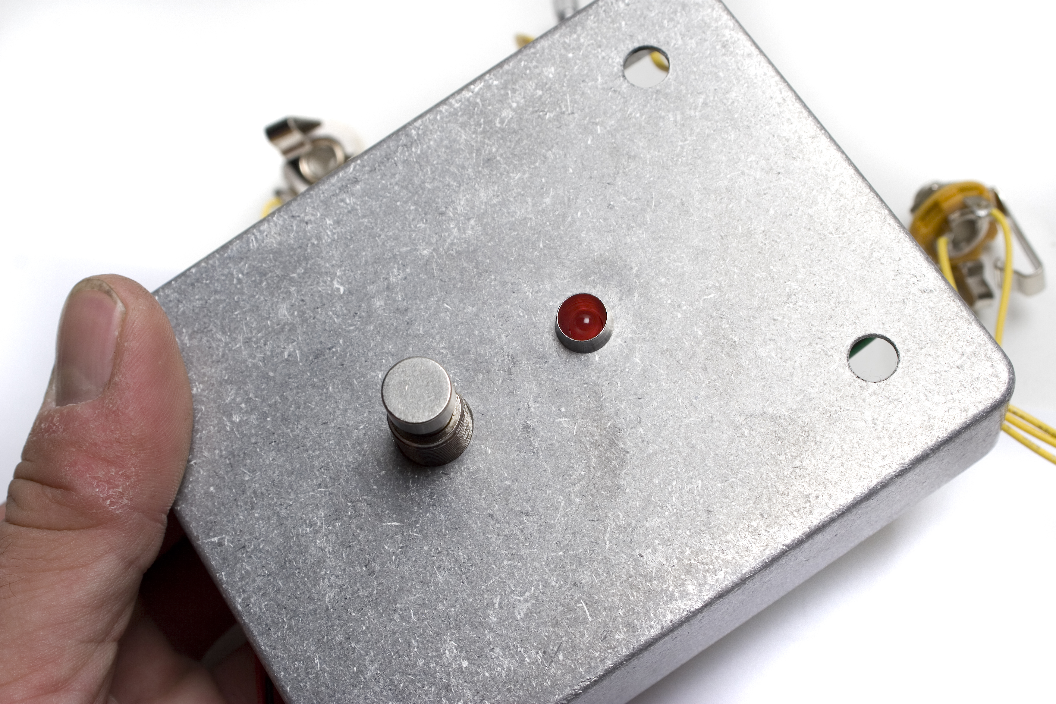
Face the Fuzz Enclosure Test Fit
Hold the pedal up to the inside of the enclosure, with the stomp switch going through the hole, like shown above. While doing this, push the LED so that it is visible inside the bezel, like shown in the picture above. Then bend the leads so that it will stay in place. Flip the project over and solder the LED in place, clipping the leads after.
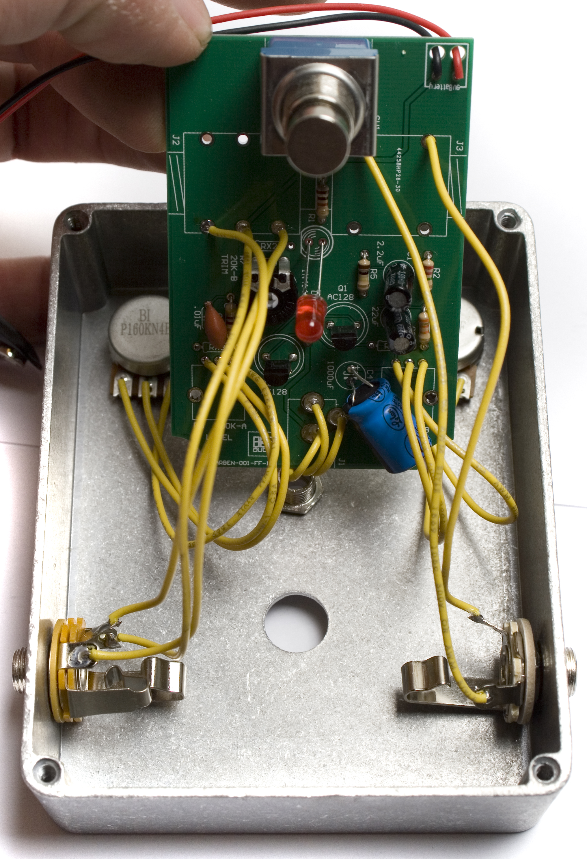
Biasing Guide:
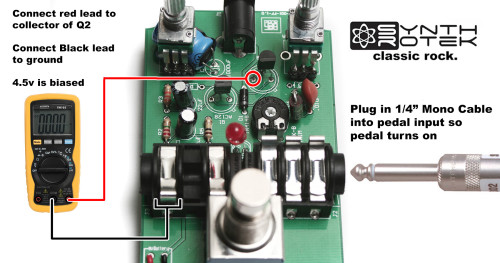
For the Fuzz Face circuit to be optimally biased, the collector of Q2 needs to be at 4.5 volts. (When connecting the Arbiter Fuzz Face Clone circuit to your multimeter as shown in the photos below your meter will read -4.5v) The 20K trim pot is used to dial in this value. You will need a multi-meter that reads DC voltage to accomplish this, which can be found very inexpensively at places like Harbor Freight Tools. All you need to do is connect your leads to a ground on the PCB and the collector of Q2 to get this reading. (Pedal must be powered on)
DC Jack Install
Face the Fuzz DC Jack Install
Next, insert the DC jack through the hole at the top of the enclosure, and tighten the nut on the outside.
Potentiometer Install
Face the Fuzz Potentiometer Install
Now we can install the potentiometers in the enclosure. Insert them through their respective holes, and tighten the nuts on the other side. If you wish to use washers, place them on the potentiometers before tightening the nuts, they will prevent the nuts or the tool from scratching the enclosure during install.
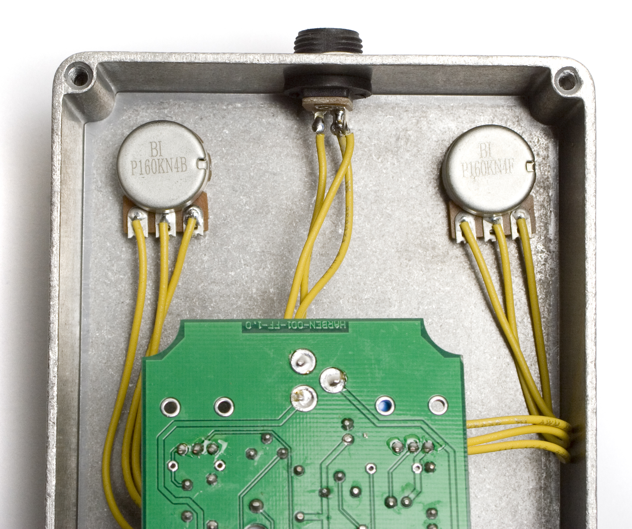
Input / Output Jack Install
Face the Fuzz Jack Install
Next, insert the audio jacks through the holes in the enclosure. Place the washers on the jacks, and hand tighten the nuts on them. It is not recommended to use a tool on these jacks, as they may strip out easily.
Final Install
Face the Fuzz Final Install into Enclosure
Next, put the board assembly back into place, fitting the stomp switch through its hole, and making sure the LED still lines up. Put the plastic washer down first, and then tighten the nut down on top, securing everything in place.
Completed Project
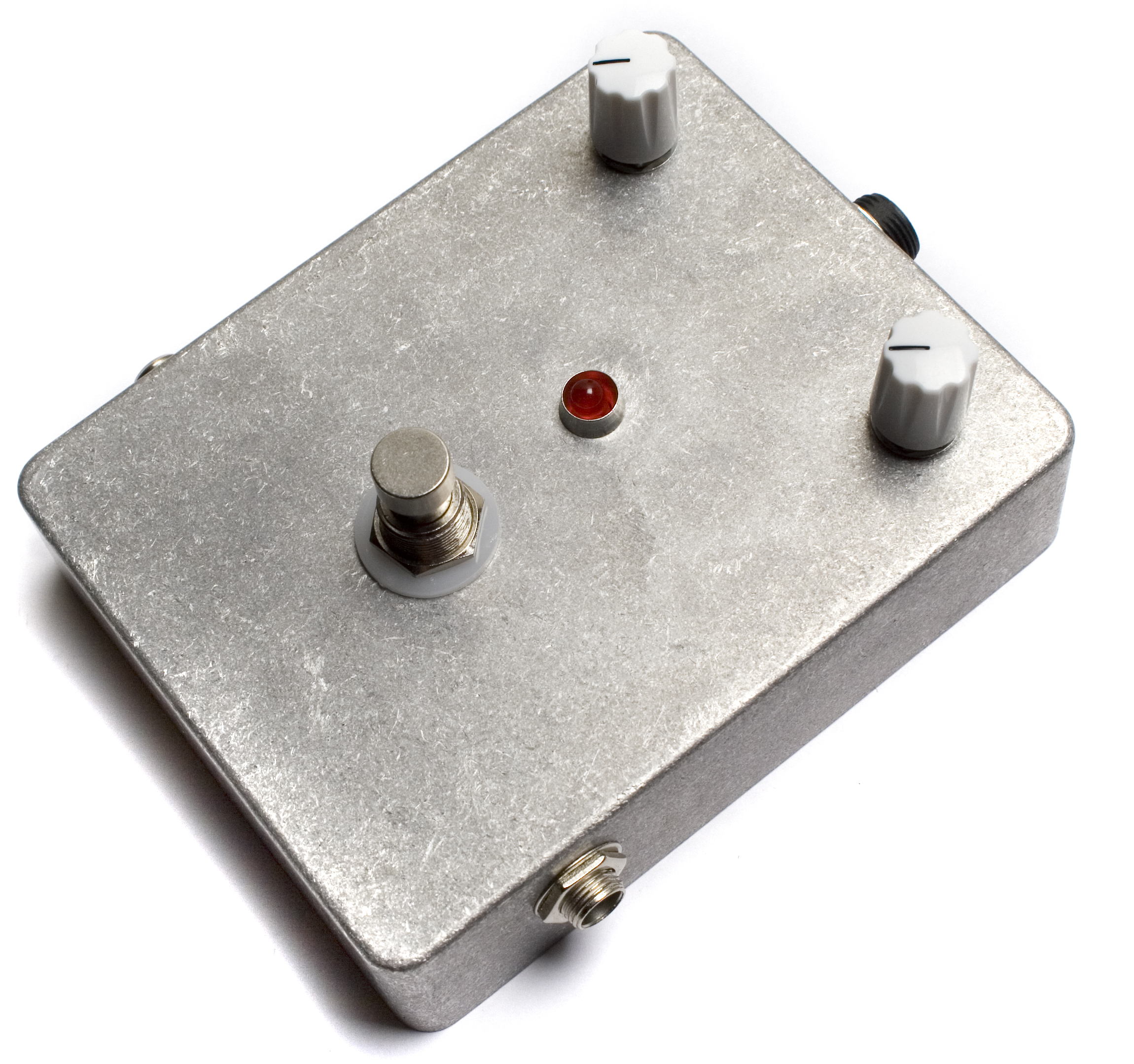
Face the Fuzz Wired Version Completed
Congratulations on building your Face the Fuzz Wired Version DIY Kit!
If you have any comments or questions, feel free to contact us.
Trouble with your build? Take a look at our Troubleshooting Guide, it has lots of useful info in there that can help you get your build working right.