


Important Links
Product Page
Store Page
Assembly Instructions
Bill of Materials
Quick Start Guide
Programming Instructions
QC Instructions
Capacitor and Resistor Lookup Guide
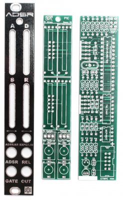
Synthrotek ADSR Assembly Instructions
Thank you for purchasing the Synthrotek ADSR kit! This is an easy to intermediate build. It is very important to get all the components properly soldered into the PCB in the correct placement. If you feel like you can handle it, please proceed! If not, get some help from a friend with experience or purchase a fully completed unit.
Please build according to the BOM, and not these instructions or the pictures alone. Some components may have changed since these were written, or we may not be able to get the proper components in the pictures.
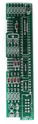
Diodes
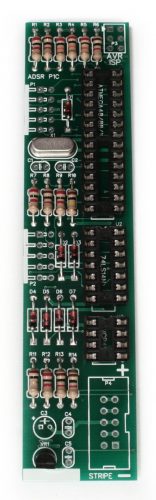
First thing we are going to populate is the diodes. Following the BOM, insert all the diodes into their proper spots, paying attention to the polarity. Diodes are polarized components, and must be populated correctly to function. Make sure to align the cathode stripe on the diode with the cathode marking on the silkscreen.
Then you can flip your project over onto a flat surface and solder all the diodes in place. Then clip the excess leads.
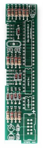
Resistors
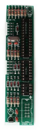
Next up are the resistors, which are not polarized so it doesn’t matter which way they are placed in, but it makes troubleshooting a lot easier if you line up all of the tolerance bands (usually a gold stripe) on the same side. Insert each resistor, matching the value to the proper spot as per the BOM.
Once they are all in there, carefully flip your project over and solder the resistors in place. Clip any excess leads.
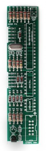
Crystal and Voltage Regulator
Now we can populate the crystal and the voltage regulator. Crystals are non polarized, so it doesn’t matter which way you place it.
The voltage regulator needs to be placed with the flat side of the regulator matching the flat side on the silkscreen. If it is populated backwards, you WILL damage your module.
Once you have populated both components, flip your project over, solder everything in, and clip any excess leads.
IC Sockets
IC Sockets are next up on the list. When populating them, make sure to align the semi-circular notch in the socket with the same looking notch in the silkscreen. Once you have them in there, an easy way to get them flat is to only solder one leg of each (maybe two in the 28 pin socket’s case). Then you can go back and reheat the solder points and gently apply pressure to sit them flat. Then go back and solder all the remaining legs on the IC sockets.
Ceramic Capacitors
Now we can populate all the ceramic capacitors. These are non-polarized, so it doesn’t matter which way they are placed in the board, but to make troubleshooting easier, its recommended to place them in such a way that they can be easily read later on. Once you have them all in, carefully flip your project over and solder everything in place, clipping any excess leads.
Power header and ISP Header
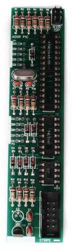
Next up is the 10 pin shrouded header for the power connection, and the ISP Header, which is used to update the firmware on the ADSR. For the 10 pin shrouded header, make sure to align the notch in the header with the similar notch in the silkscreen. This will allow you to plug in your power cable correctly. The 6 pin ISP header doesn’t matter which way you place. Once they are both in, carefully flip your project over and solder everything in place. You can use the same trick used earlier with the IC sockets to get the headers flat.
Electrolytic Capacitor
Next up is the single electrolytic capacitor. This component is polarized, so make sure when you are placing it that you get the longer leg in the square hole, that is closer to the + symbol. Once in, flip your project over, solder and clip any excess leads.
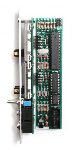
Control Board Headers
Now that the logic board is done, lets move on to the control board.
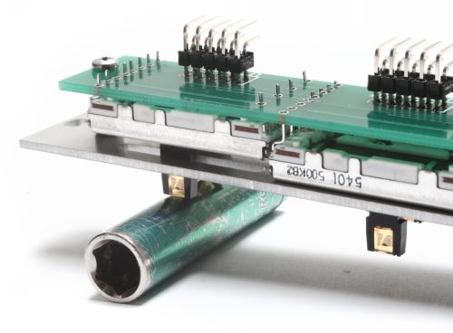
We are going to start with the right angle headers that connect the two boards together. When you insert these, make sure to align the ‘right angle’ pins with the indication on the silkscreen. These CAN NOT be soldered directly to the board, or the two boards will not fit together properly. The easiest way to get the headers properly spaced is to insert another PCB, or the front panel, between the plastic base of the headers and the control board, like the picture below.
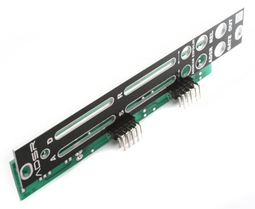
Then, carefully, flip the project over so you can solder just one pin of each header.
Once you have one pin on each soldered, hold the board up, and make sure that everything is straight. you want the headers coming off the board at a 90 degree angle, and the other part of the header to be parallel with the control board. Once everything looks good, go ahead and solder the remaining pins.
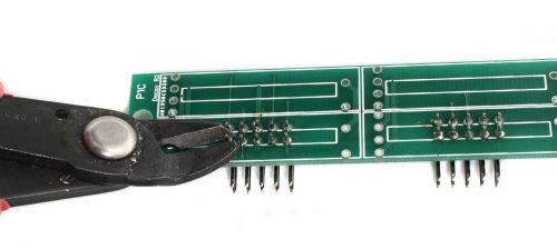
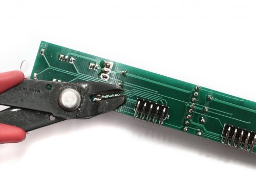
Next, clip all the pins as shown above, making sure to get them as close to the board as possible without damaging anything. Once they are clipped, it is highly recommended to reheat all the solder joints to make absolutely sure that they are connected. Once the slide pots are in, it will be impossible to get at these solder joints.
Control Board Components
Next, populate all of the front panel components, making sure that everything is sitting nice and flat, but DO NOT SOLDER ANYTHING YET. Now would be a good time to also put the 10mm hex standoff on the board. Hold a screw up through the hole from the bottom, and twist the standoff down onto it until it is fully seated on the PCB.
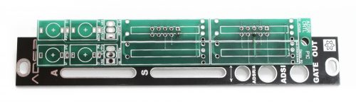
Front Panel
Next, place the front panel over all the components, and then hand tighten all the nuts. Once everything is seated nice and flat, go through with a tool and tighten all of the nuts for the jacks and switches.
Next, insert the 2.5mm screw into the standoff, through the front panel, and use a phillips head screwdriver to tighten it down.
Once the front panel is on and tight, make sure all the components are still flat against the PCB (the slide pots wont stay, but we have a trick for those coming up). Then flip over your project and solder everything but the slide pots into place.
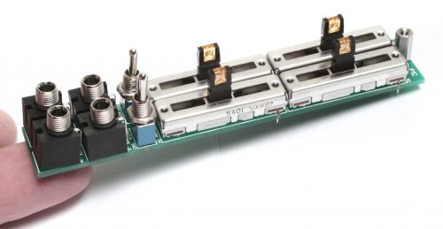
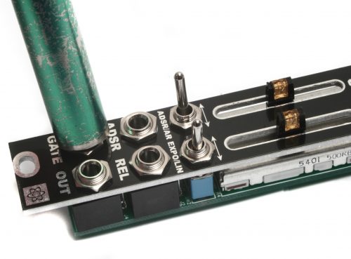
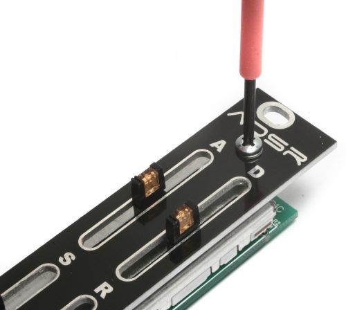
For the slide pots, you can use a tool, or other object to place between the slide pot slider and the table to hold it against the PCB. While this is in place, solder one leg of each slide pot.
Then repeat this for the other set of slide pots. Once all four are flat and straight, solder the remaining pins into place.
Because of how these boards need to come together, clipping all of the leads on the back of the control board is necessary. Like with the right angle headers, go ahead and retouch all of the solder joints, just to make sure they are solid. You are not going to want to try and do any re-work once these are together.
Mating the two boards
Now its time to attach the two boards to each other. Align the right angle headers from the control board assembly so that they will fit into the holes on the logic board. Insert them fully, and solder just one leg on each.
Next, make sure that the spacing (gap) between the two boards is the same all the way down the board, like in the picture below. Also make sure that the logic board is as close to a 90 degree angle as possible.
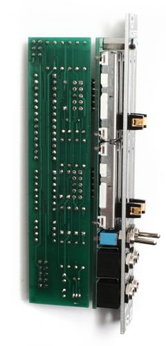
Once you are sure that everything is straight and even, solder the remaining pins on the headers.
ICs
The last thing to do is insert the ICs into their sockets. Following the BOM, insert each IC into its respective socket, making sure to align the notches in the ICs with the same notches in BOTH the sockets and the silkscreen.
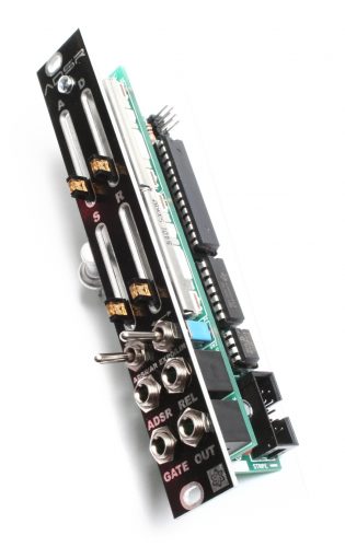
Completed Module
Congratulations on successfully building a Synthrotek ADSR! If you are having any issues with your build, head on over to the troubleshooting guide, but if that doesn’t help, you can always email us at store@synthrotek.com
Want to check and see if your module is working properly? Keep on reading, and you will find our QC Instructions below.
Programming Instructions
If you purchased a kit from us, you will not need to program your module, as your attiny chip came pre-programmed. Just plug in and you’re good to go. If you sourced your own parts, or if you need to update the firware, just follow the instructions below to reprogram your attiny chip.
Things you will need
- ISP programmer
- A computer with avrdude installed
- A completed ADSR unit
These Instructions will show you how to reprogram your adsr unit with avrdude, which is a command line utility. You can use any program you like, as long as it can load an intel hex formatted file over 6 pin ISP protocol.
First, download adsr.hex, and place it in an easily accessible folder (you may need to right click and ‘save as’). Next, open up a command line tool and navigate to the folder you just put adsr.hex into, and type the following commands, one at a time:
avrdude -c PROGRAMMER_NAME_HERE -p m88 -u -U hfuse:w:0xdc:m -U efuse:w:0xf9:m -U lfuse:w:0xff:m
Just replace PROGRAMMER_NAME_HERE with the name of your programmer, and you should be good to go. For example, if you are using usbasp, the first command would look like “avrdude -c usbasp -pm88 -V -U flash:w:adsr.hex”
You may or may not receive an error or verification mismatch while writing the fuse bits (second command) before worrying too much, follow the QC instructions below to see if it is working or not.
QC Instructions
So you built the module, but how do you know if its working? Read on to find out how we check our modules in shop.
Things you will need
- A eurorack setup
- Patch cables
First, plug the ADSR into your eurorack power via the included 10 to 16 pin power cable. Start with both switches to the left. When you power your system on, you may see one or more of the slide pots flash. Patch the output of the ADSR into a VCA, and have an audio source going through the VCA as well.
-
- Change the left switch from ADSR to AR.
- The R slide pot should flash
- Change the left switch from ADSR to AR.
-
- Change the left switch back to ADSR
- All four slide pots should flicker
- Change the left switch back to ADSR
-
- Move the A and D sliders halfway up
- The lights should go back and forth between A and D
- Move the A and D sliders halfway up
-
- Run a very slow clock into the Gate jack
- Move the A and D slide pots to about 1/4 of the way up, move S and R to about half way
- The lights should cycle through all four steps, in time with your clock.
- If it isn’t try slowing your clock down.
- The lights should cycle through all four steps, in time with your clock.
- Switch from ADSR to AR
- The lights should now only toggle between A and R
- Switch from EXPO to LIN
- You should hear the difference in the ramp of the envelope.
- Give the ADSR jack some sort of CV input
- You should hear the entire envelope get longer in correlation with how much voltage is going into the ADSR jack.
- Give the REL jack some sort of CV input
- You should hear just the R stage of the envelope lengthen in correlation with how much voltage is going into the REL jack.
If your module passed all the previous steps, then you are good to go! Enjoy your new Module!