Important Links
Product Page
Store Page
Assembly Instructions
Bill of Materials
Capacitor and Resistor Lookup Guide
Thank you for purchasing the Synthrotek TST Kit! This is an easy to moderate build. There are some surface mount parts that need to be soldered directly to the PCB, which is different from through hole soldering. It is very important to get all the components properly soldered into the PCB in the correct placement. If you feel like you can handle it, please proceed! If not, get some help from a friend with experience or purchase a fully completed unit.
USE THIS MODULE AT YOUR OWN RISK!!!
You will be exposing electricity to the front of your modular system. Be careful not to dangle patch-cables, etc. on the exposed pins. This may damage modules and your power supply. Be smart and safe!
Please build according to the BOM, and not these instructions or the pictures alone. Some components may have changed since these were written, or we may not be able to get the proper components in the pictures.
Let’s Begin!
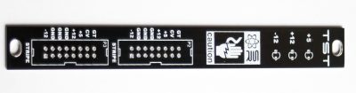
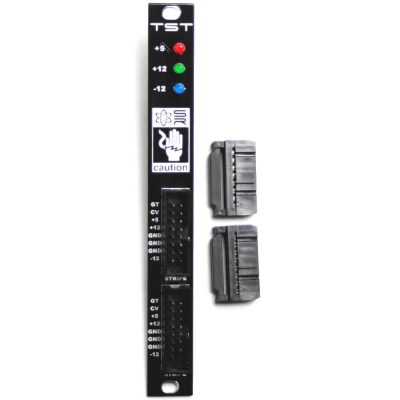
TST – Eurorack Panel
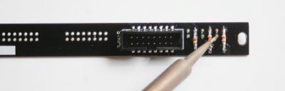
RESISTORS
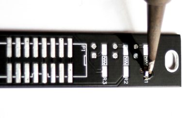
TST-Resistors
First add a small amount of solder to the pads on one side of R1, R2 and R3 as shown above. This will help tack down the 1/8th watt resistors.
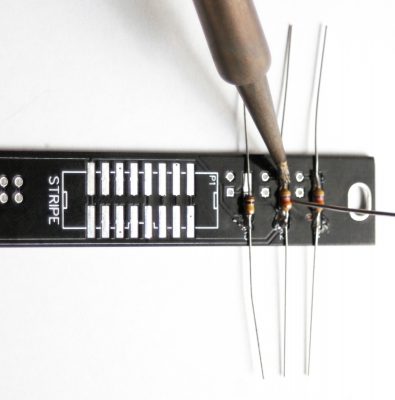
TST Resistors 2
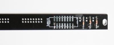
Now place the resistors on the pads and solder the side that you tinned first, then solder the other side down. These resistors are non-polarized, so you can put them in either direction.
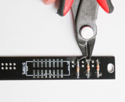
TST- Clip Resistor Leads
Carefully clip the excess resistor leads.
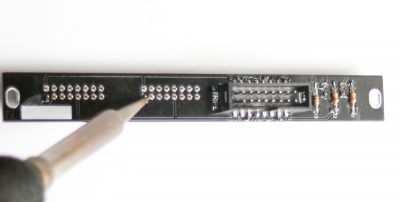
SMT EURORACK POWER HEADER
SMT Eurorack Header
Tin one of the pads on the SMT Eurorack Power Header.
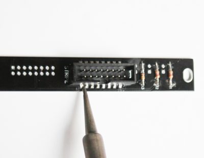
TST – SMT Header Soldering
Place the SMT power header and align the notch of the header with the notch on the PCB. Orientation matters here! Solder all the pins carefully to the pads. Take your time!
LEDs
TST – LED’s
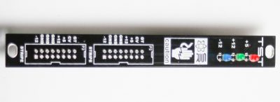
The LEDs are polarized components, so when populating it, make sure that you align the flat side of the LED with the flat side that is indicated on the PCB. The flat side of the LEDs should face the indication numbers (ie +5, +12, -12)
When soldering these components into place, make sure that the LED is nice and flat and sitting straight. Place the LEDs flush to the PCB then solder everything in place and clip any excess leads.
TST LED Soldering
Flip the board over, solder the LEDs in place and then cut the excess leads.
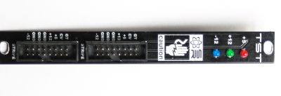
THROUGH HOLE POWER CONNECTORS
TST – Through Hole Power Connectors
On the front of the PCB/Panel place the through hole power connectors and make sure that you align the notch on the header’s shroud with the notch on the PCB. Again, orientation matters! Carefully flip the board over and solder the pins.
TST
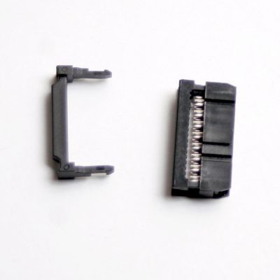
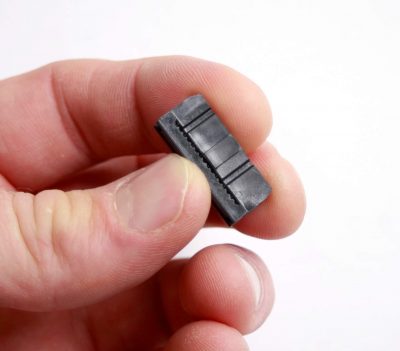
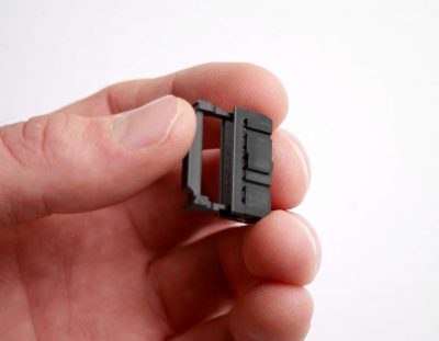
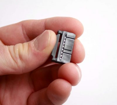
16 pin plug and strain relief
Snap the 16 pin plug together, then snap in the strain relief.
Insert the plugs into your TST. Keep them plugged in unless you need to test a module.
Congrats! You are done. Again USE AT YOUR OWN RISK and BE CAREFUL. Synthrotek is not responsible for any system damage!