


Important Links
Product Page
Store Page
Assembly Instructions
Bill of Materials
Schematic
Capacitor and Resistor Lookup Guide
Eurorack Dual Triple Response VCA Assembly Instructions
Thank you for purchasing our Eurorack VCA Kit. This is an intermediate to advanced build, so please follow the instructions in order and use the bill of materials and the not the photos alone as the BOM will have the most up-to-date and best functioning part list. You will need a soldering iron (higher watt temperature controlled is ideal), precision wire trimmers, needle-nose pliers and some tools to tighten the nuts in place (ie, a socket set or wrench). Let’s get started!
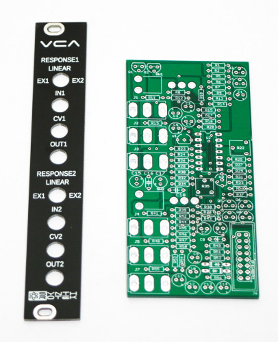
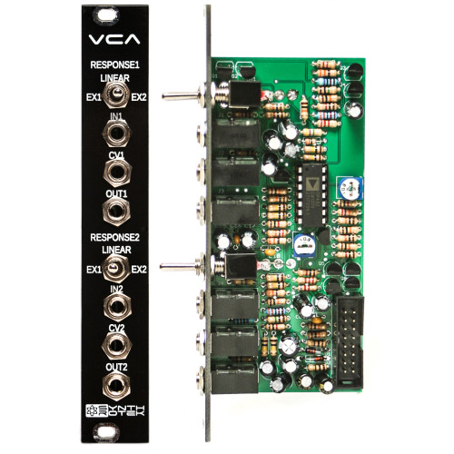
Eurorack VCA Panel & PCB
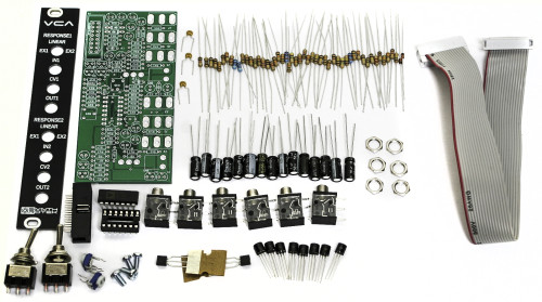
Eurorack VCA Full Kit
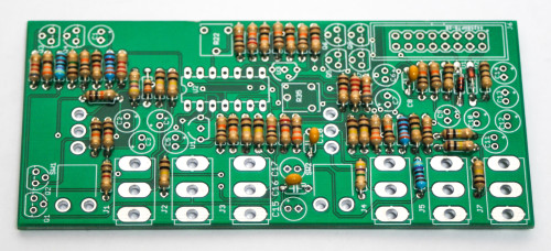
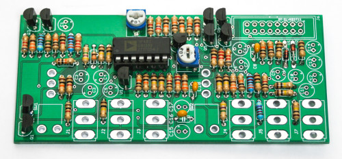
Resistors and Diodes

Eurorack VCA Resistors and Diodes
Begin by populating the PCB with the resistors and diodes. This will allow you to place the project upside down and solder while keeping the resistors and diodes flat to the pcb. This project has LOTS of resistors that are obviously tightly placed on the PCB, so take your time and feel free to solder the resistors in multiple stages, as this will make the build much easier. Solder and trim leads. Keep some your trimmed resistor leads handy, as you will need some at a later stage.
Ceramic Capacitors
Eurorack VCA Ceramic Capacitors
Now populate the three ceramic non-polarized capacitors into their respective locations on the PCB. Solder and trim leads.
Trimmer Potentiometers
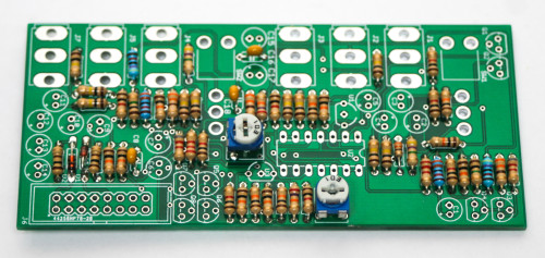
Eurorack VCA Trimmer Pots
Next, populate the two trimmer pots in place, turn pcb over and solder.
Transistors, IC Socket and IC
Eurorack VCA Transistors and IC
Start with placing the IC Socket into the pcb by aligning the small notch on one of the ends with the notch on the PCB silkscreen graphic. Turn over and solder. Now place all the transistors in place by aligning the flat side of the transistors with the flat side on the PCB silkscreen graphic. Turn board over solder and trim and finally (and carefully) place the IC into the socket by aligning the notch on the IC with the notch on socket and silkscreen. Take your time on this as this high quality op-amp is an expensive IC to replace if damaged.
Electrolytic Caps and 16 Pin Power Header
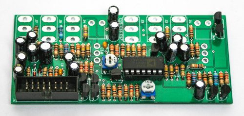
Eurorack VCA Electrolytic Caps and 16 Pin Power Header
First place the 16-pin power connector header pins into the PCB by aligning the notch in the shroud of the header with the notch on the PCB silkscreen graphic. Turn over, press down the table, and solder in place and quickly as to not melt any pins out of the plastic shroud. Now populate all of the polarized electrolytic capacitors by placing the longer lead of the capacitor into the hole that has a ‘+’ marking closest to it on the silkscreen. Solder and trim.
3.5mm Jacks
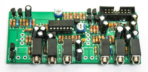
Eurorack VCA 3.5mm jacks
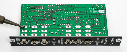
Start by adding all six jacks to the pcb then hold them in place and flip the board over. Solder ONLY the center pin of of each the jacks as shown below. While soldering, push the threaded part of the jack as far away off the end of the PCB as possible.

Eurorack VCA Solder center pin of jack
At this time place the panel and tighten down the nuts (don’t over-tighten), as shown below.
Eurorack VCA Panel Assembly
Finish soldering the rest of the jack leads, then trim.
Eurorack VCA soldering remainder pins of jacks
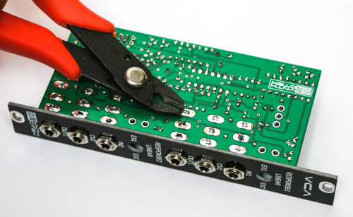
Eurorack VCA Jack Trimming
SPDT (on-off-on) Switches
Take off all the nuts and washers EXCEPT for the bottom nut for each switch and unscrew it so that it is in the middle of jack shaft as shown below.
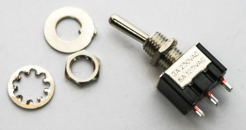
SPDT (On-Off-On) Switch Nuts
Place each switch into the panel as shown below.
Now use the other nut, that you removed from the switch initially, and tighten it down on the switch over the panel. Keep the switch 90 degrees to the main green pcb.
Eurorack VCA Attaching Switches to Panel
Take six of the saved trimmed resistor leads (three for each switch) and bend a small hook into one of the ends with some needle-nosed pliers as shown below.
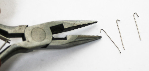
Eurorack VCA switch connecting wire
Now thread the hook through the three solder lugs on each of the switches, then take the other end and put it through the hole on the pcb as shown below. This can be a little tricky, take your time.
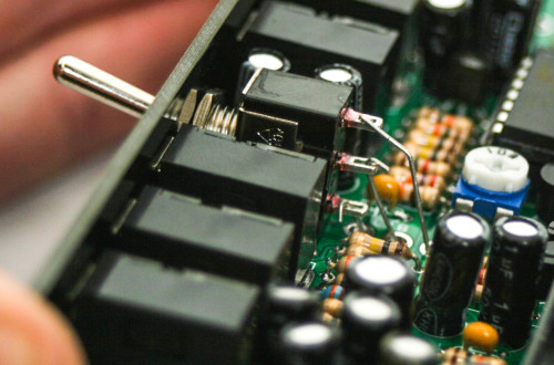
Eurorack Switch Leads
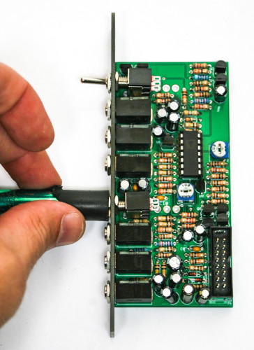
Now solder the hooked jacks first, then turn over and solder the other end of the resistor leads to the PCB.
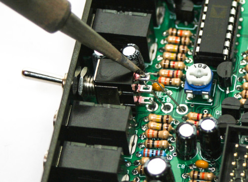
Eurorack VCA Switch Soldering
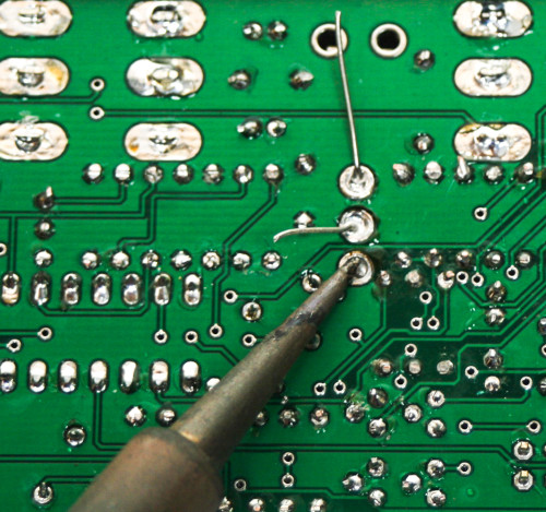
Eurorack VCA PCB soldering
Trim those leads up and CONGRATS! You are now ready to test your unit. If the unit does not function at all or as intended, please check out our Troubleshooting Guide. Thank your choosing Synthrotek!
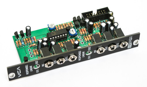
Complete Synthrotek Eurorack Dual VCA
Calibration & Testing Procedures
NOTE: There is one procedure that requires an Oscilloscope.
Set up an Oscillator with a fairly high frequency signal and take the output and plug it into IN1 on the VCA. Now take a +5V linear Envelope and take the output and plug it into CV1. You will want to monitor the output with an Oscilloscope. Whenever the Envelope is active and the RESPONSE1 switch is set to LINEAR, you should see a linear 10V peak to peak signal. Now set the switch to EX1 and take note of its level (peak to peak) and shape when monitoring. Now set the switch to EX2 and get ready to adjust the trimpot R22 (upper right section of the board). You should notice that this curve is steeper / more exponential than EX1 and that the level is hotter. You’ll want to turn the trimpot down until the level of EX2 matches EX1.
Now we’ll switch all the cables down to the second part of the VCA and calibrate and test it.
Whenever the Envelope is active and the RESPONSE2 switch is set to LINEAR, you should see a linear 10V peak to peak signal. Now set the switch to EX1 and take note of its level (peak to peak) and shape when monitoring. Now set the switch to EX2 and get ready to adjust the trimpot R35 (middle lower section of the board). You should notice that this curve is steeper / more exponential than EX1 and that the level is hotter. You’ll want to turn the trimpot down until the level of EX2 matches EX1.
Congratulations! You just successfully just built a Eurorack Dual Triple Response VCA module from Synthrotek! If you need help with your build, please check out our Troubleshooting Guide.
Thanks for choosing Synthrotek!